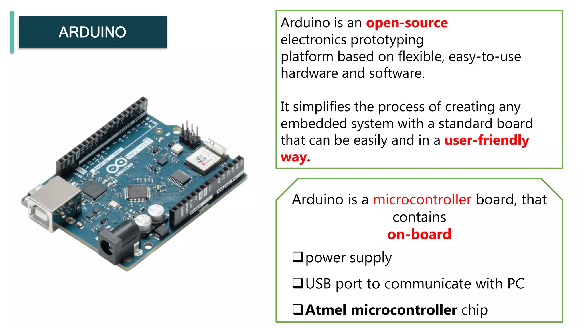
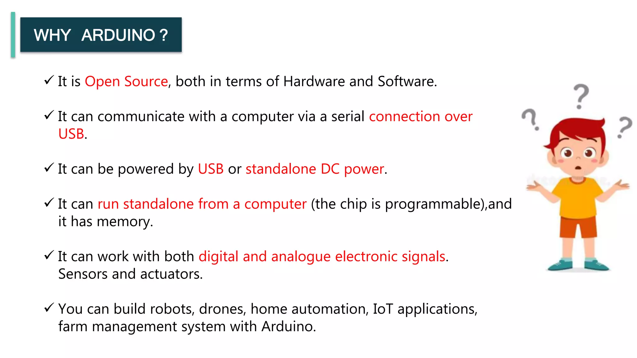
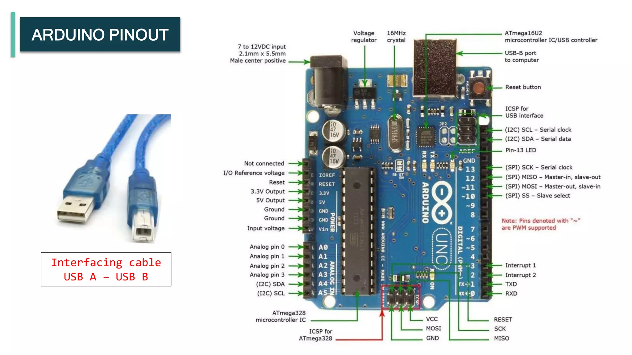
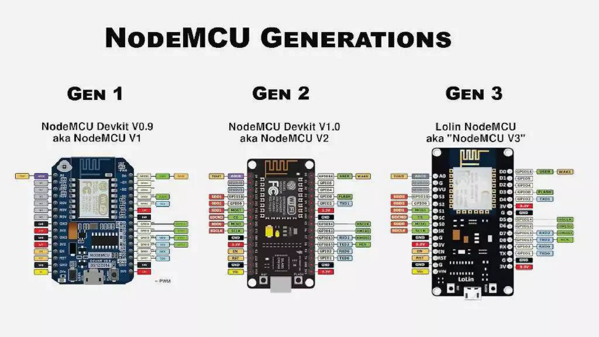
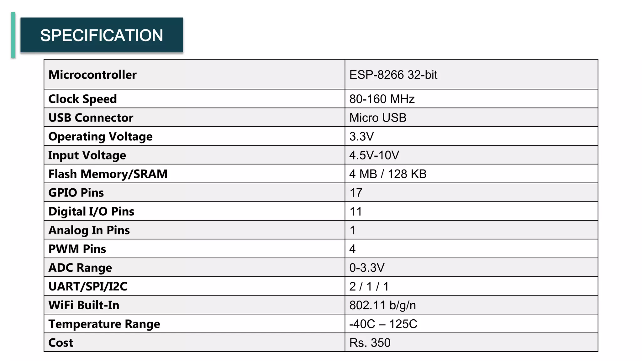
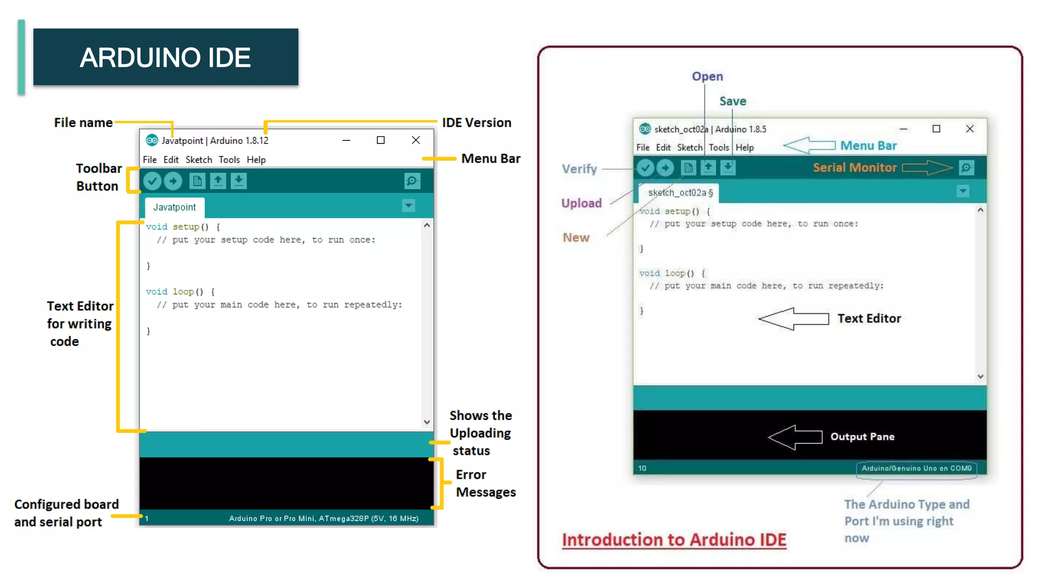
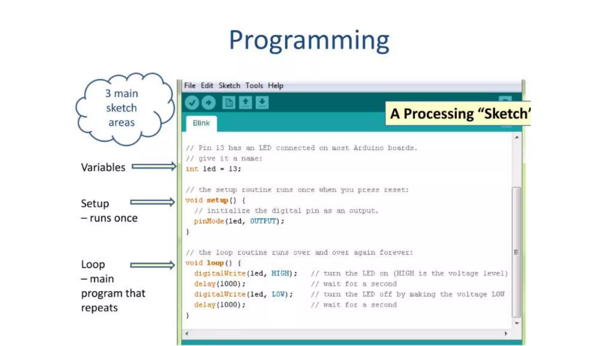
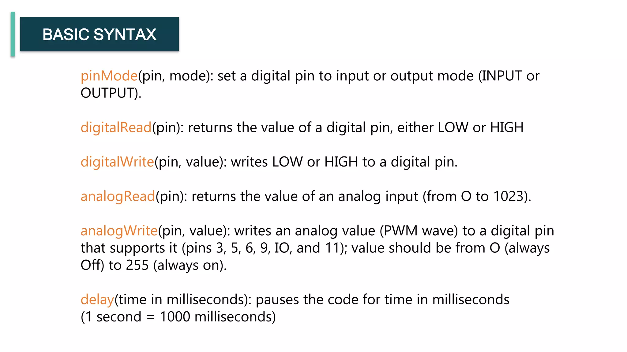
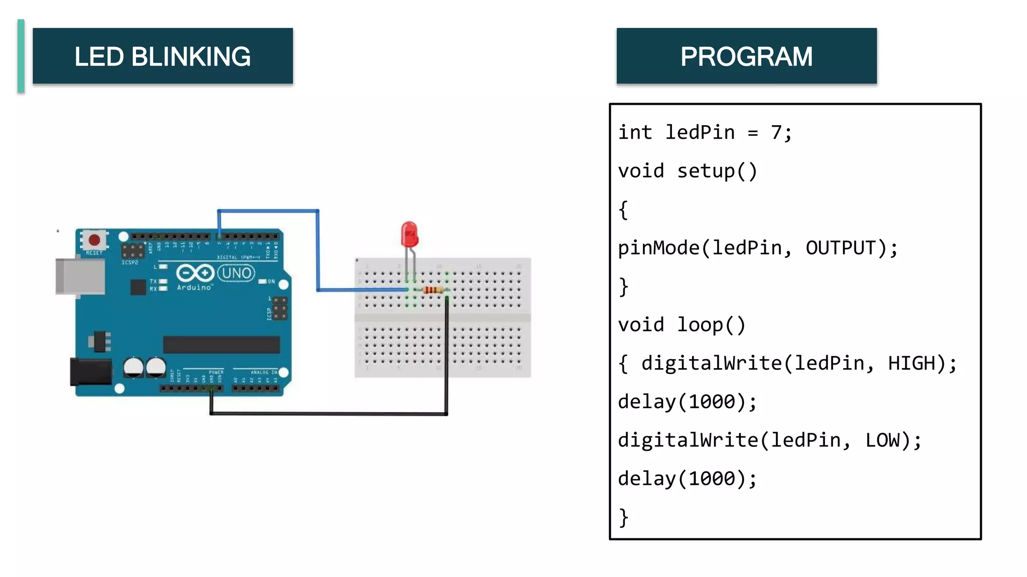
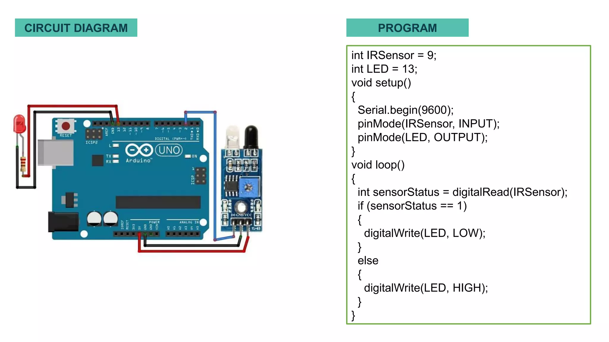
This document provides an introduction to microcontrollers and compares the Arduino and NodeMCU platforms. It discusses the history and evolution of Arduino, describing its key features like onboard power supply, USB port, and Atmel microcontroller chip. Pinouts and specifications of the Arduino UNO and NodeMCU boards are presented. The document also covers programming Arduino using the Arduino IDE, examples like an LED blinking circuit, and applications of Arduino and NodeMCU in areas like IoT, home automation, and education. It concludes by discussing the future scope of these platforms with AI and their suitability for different types of projects.

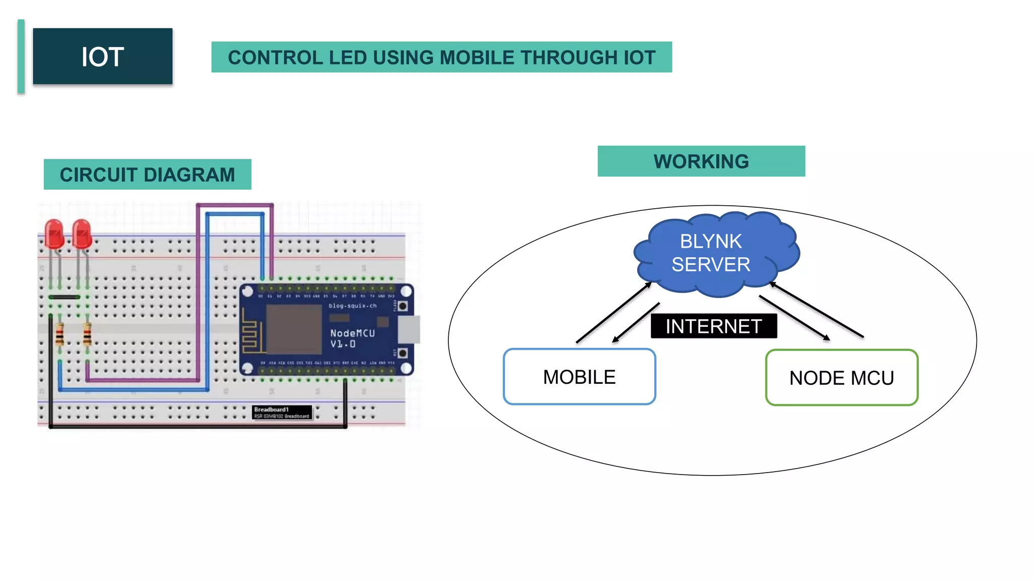
![#define BLYNK_PRINT Serial #define BLYNK_TEMPLATE_ID "TMPLtYPT9XZa" #define BLYNK_TEMPLATE_NAME "HASANAUTOMATION" #defineBLYNK_AUTH_TOKEN"JvZcHDC3F1j2Mwh5yvTKDNCeSfN6TK4" #include <ESP8266WiFi.h> #include <BlynkSimpleEsp8266.h> char auth[] = "JvZcHDC3F1j2Mwh5yvTKDNCeSfN6TK4a"; char ssid[] = "OPPO Reno7 5G"; char pass[] = "hasan2412"; void setup() { Serial.begin(9600); Blynk.begin(auth, ssid, pass); } void loop() { Blynk.run(); } RELAY 5V Its an electronic control switch](https://image.slidesharecdn.com/e2214029-hasanbasari-230424091443-728e2b50/75/introduction-of-arduino-and-node-mcu-30-2048.jpg)