Downloaded 111 times
![#include<Password.h> #include<Keypad.h> #include<LiquidCrystal.h> Password password=Password("1#3*5"); int len=5;//size of password int ledRed=11;//for Wrong int ledGreen=12;//for Success int ilosc;//number of clicks LiquidCrystal lcd(A0,A1,A2,A3,A4,A5); const byte ROWS=4; const byte COLS=4; char keys[ROWS][COLS]={ {'1','2','3','A'}, {'4','5','6','B'}, {'7','8','9','C'}, {'*','0','#','D'} }; byte rowPins[ROWS]={5,4,3,2}; byte colPins[COLS]={9,8,7,6}; Keypad keypad=Keypad(makeKeymap(keys),rowPins,colPins,ROWS,COLS); void setup() { keypad.addEventListener(keypadEvent); Serial.begin(9600); pinMode(ledRed,OUTPUT); pinMode(ledGreen,OUTPUT); lcd.begin(16,2); lcd.setCursor(1,0); lcd.print("PLEASE ENTER PIN"); } void loop() { keypad.getKey(); } void keypadEvent(KeypadEvent eKey) {](https://image.slidesharecdn.com/embeddedsystemdevelopment-151018162922-lva1-app6892/75/ARDUINO-EMBEDDED-SYSTEM-38-2048.jpg)
![4.6 RFID INTERFACING Code : //add libraries to your project #include<AddicoreRFID.h> #include<LiquidCrystal.h> #include<SPI.h> #define uchar unsigned char #define uint unsigned int //class to include functions of rfid AddicoreRFID myRFID; int chipSelectPin=10; #define MAX_LEN 16 void setup(){ //led lcd.begin(16,2); lcd.println("RFID World"); pinMode(6,OUTPUT); //convert binary to human readable form SPI.begin(); //initialise or activate rfid //as setup execute only once digitalWrite(6,LOW); //initialise the rfid myRFID.AddicoreRFID_Init(); } unsigned char structure[16]; unsigned char status; void loop(){ uchar status; uchar str[MAX_LEN]; status=myRFID.AddicoreRFID_Request(PICC_REQIDL,str); status=myRFIDAddicoreRFID_Anticoll(str); if(status==MI_OK){ lcd.setCursor(0,1); lcd.print("Tag ID:"); lcd.setCursor(8,1);](https://image.slidesharecdn.com/embeddedsystemdevelopment-151018162922-lva1-app6892/75/ARDUINO-EMBEDDED-SYSTEM-45-2048.jpg)
![lcd.print(str[0]); digitalWrite(6,HIGH); delay(1000); digitalWrite(6,LOW); } myRFID.AddicoreRFID_Halt(); }](https://image.slidesharecdn.com/embeddedsystemdevelopment-151018162922-lva1-app6892/75/ARDUINO-EMBEDDED-SYSTEM-46-2048.jpg)

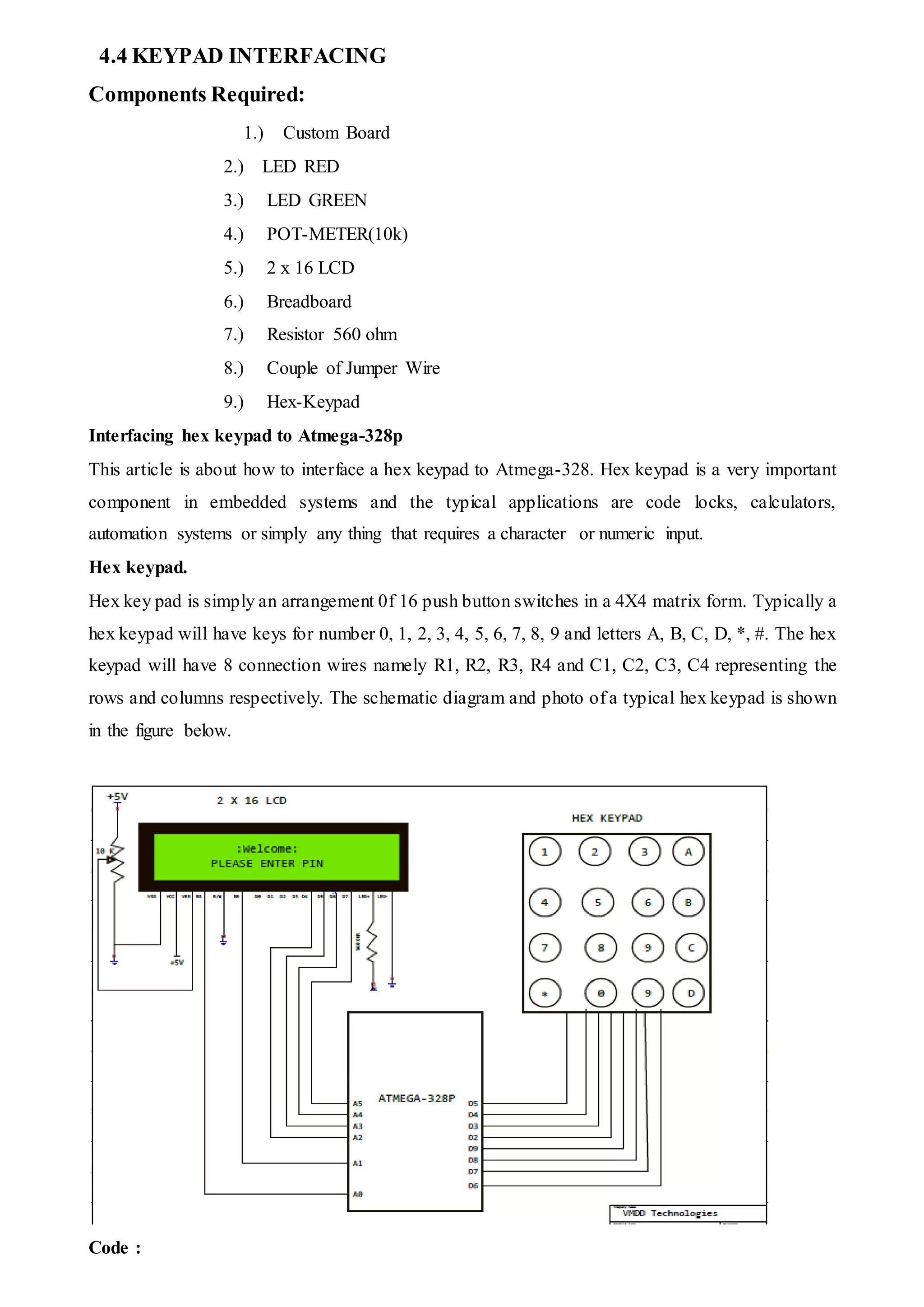
This document provides an overview of an internship report submitted by Vishal Garg about embedded system development using an Arduino Uno. It includes chapters on introducing the project aims and methodology, a literature review on embedded systems, details about the Arduino Uno board and its programming, examples of programming projects completed, and conclusions from the internship. Tables of contents and figures are provided listing the different chapters, figures, tables, and photographs included in the report.