Embedded System Isa special purpose system designed to perform a few dedicated functions. Small foot prints (in memory) Highly optimized code Cell phones, mp3 players are examples. The components in an mp3 player are highly optimized for storage operations. (For example, no need to have a floating point operation on an mp3 player!) 04/29/2025 2
Definition A combinationof hardware and software which together form a component of a larger machine. An example of an embedded system is a microprocessor that controls an automobile engine. An embedded system is designed to run on its own without human intervention, and may be required to respond to events in real time.
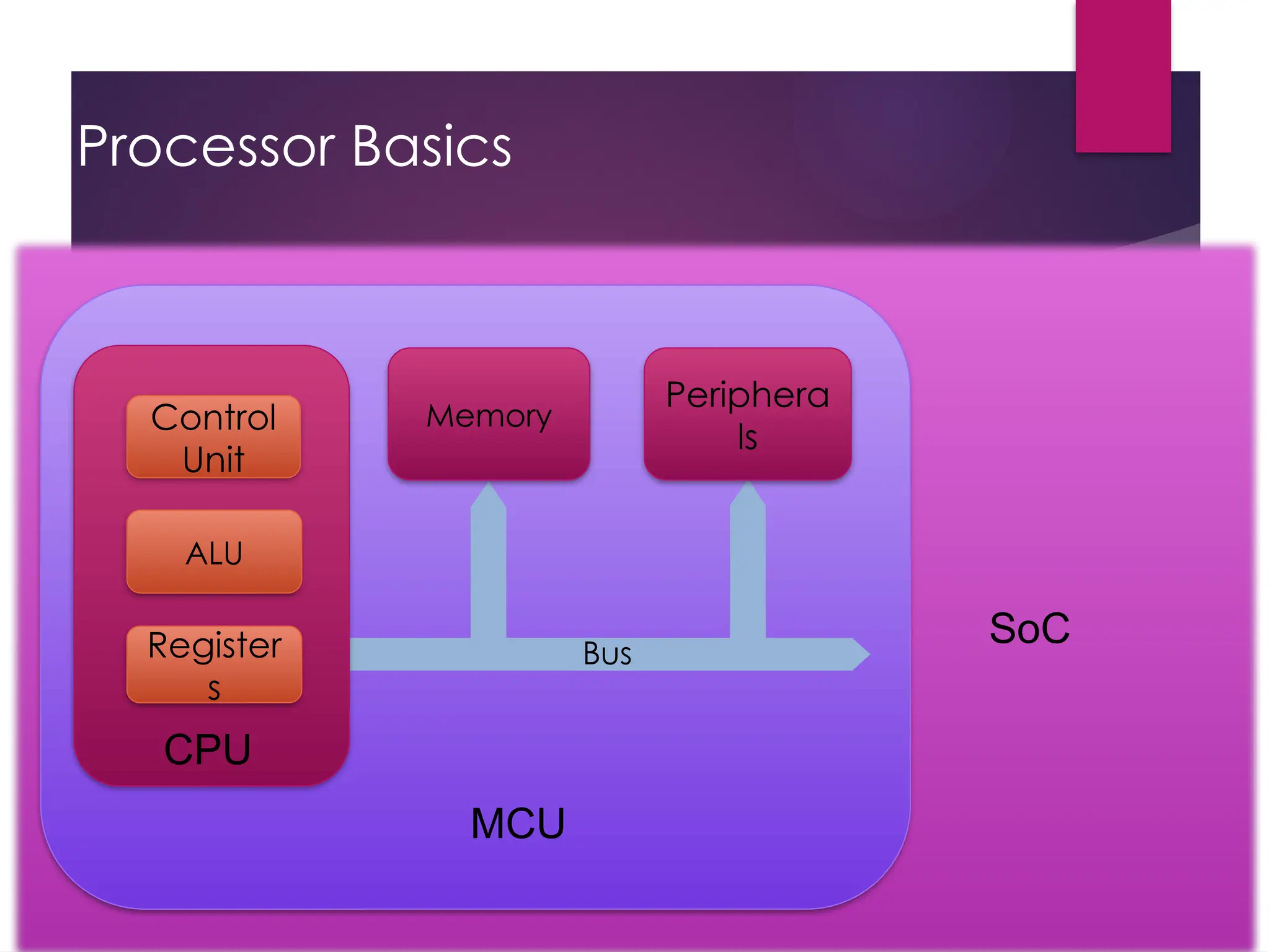
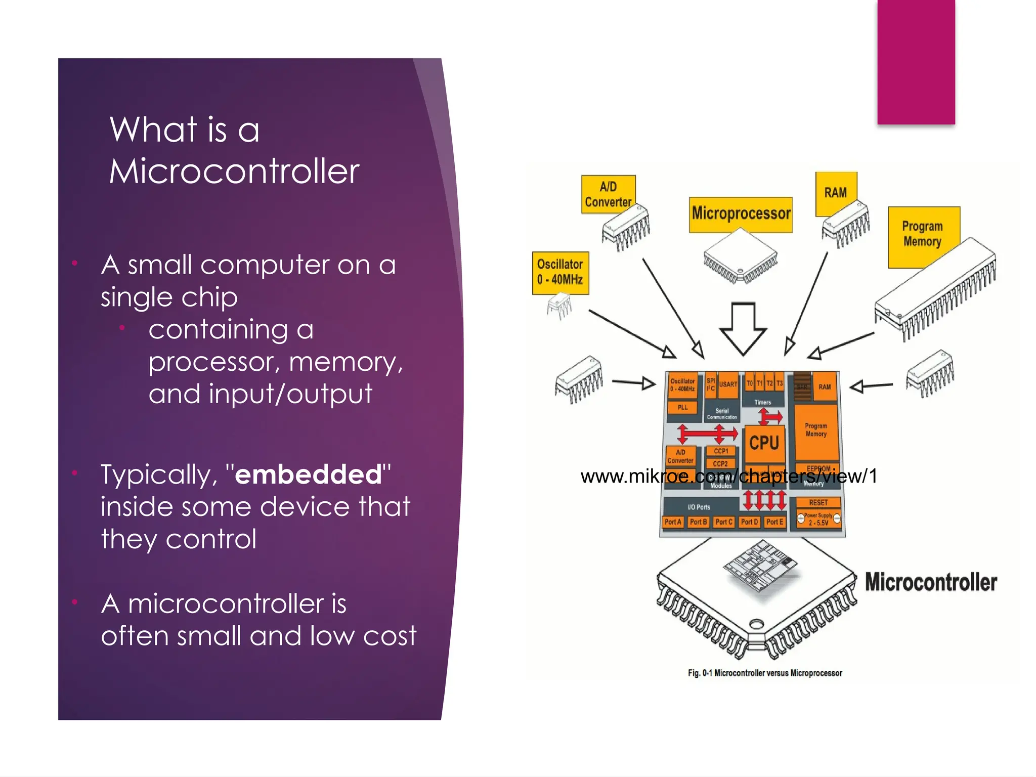
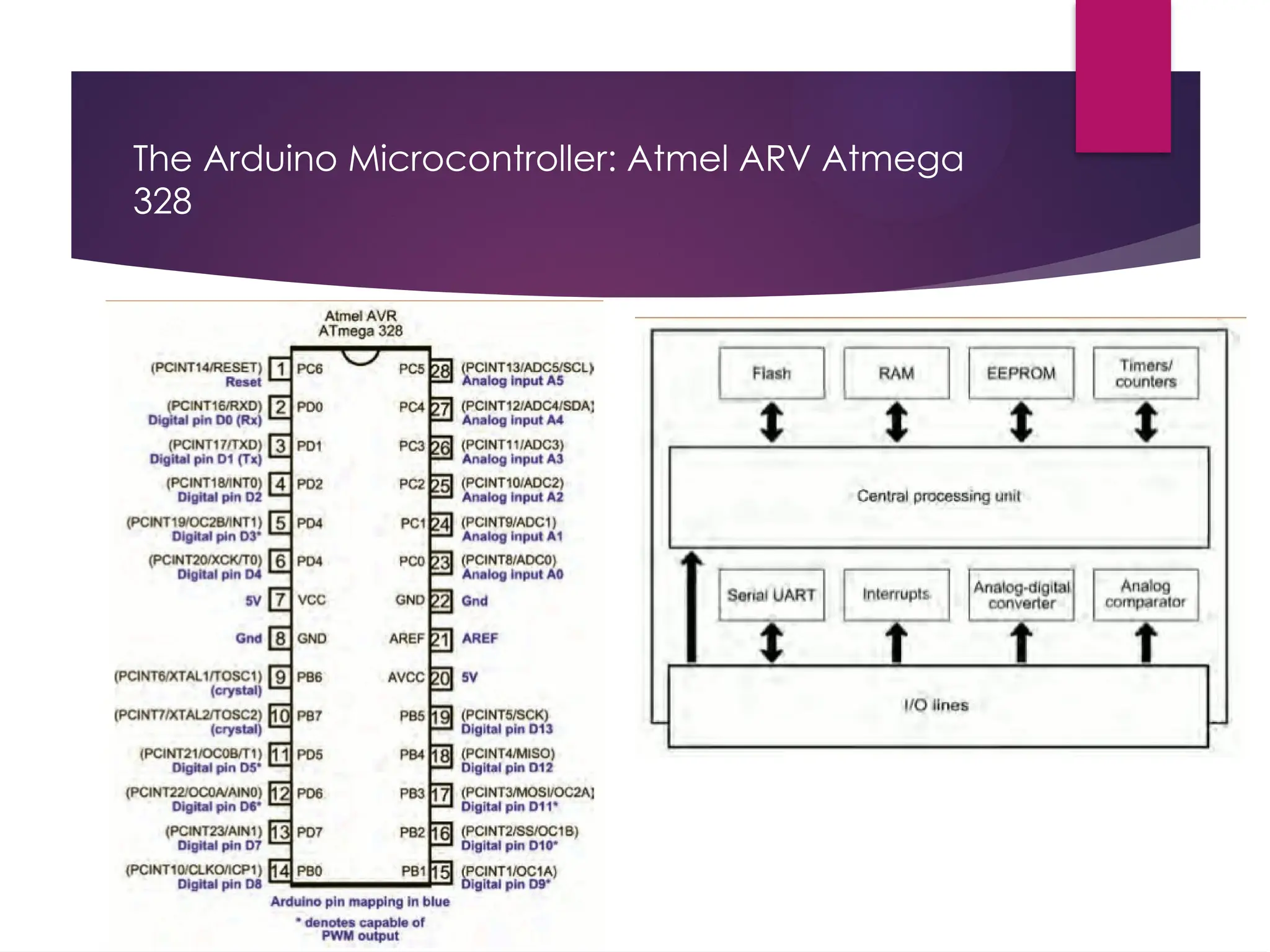
What is a Microcontroller •A small computer on a single chip • containing a processor, memory, and input/output • Typically, "embedded" inside some device that they control • A microcontroller is often small and low cost www.mikroe.com/chapters/view/1
7.
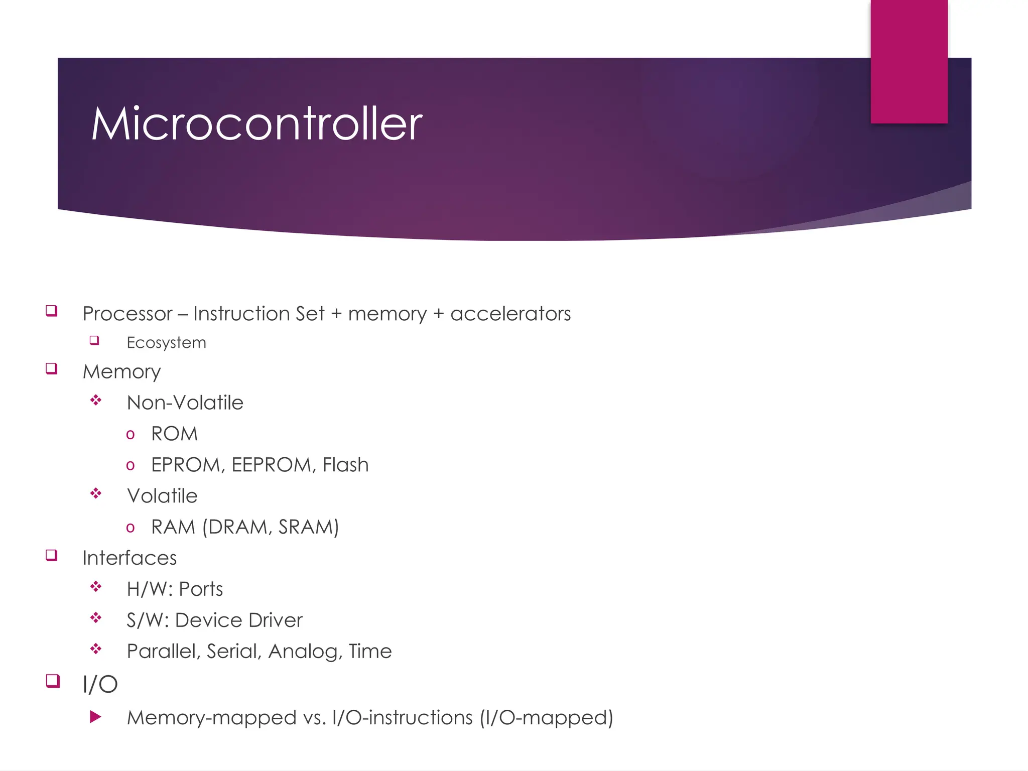
Microcontroller Processor –Instruction Set + memory + accelerators Ecosystem Memory Non-Volatile o ROM o EPROM, EEPROM, Flash Volatile o RAM (DRAM, SRAM) Interfaces H/W: Ports S/W: Device Driver Parallel, Serial, Analog, Time I/O Memory-mapped vs. I/O-instructions (I/O-mapped)
8.
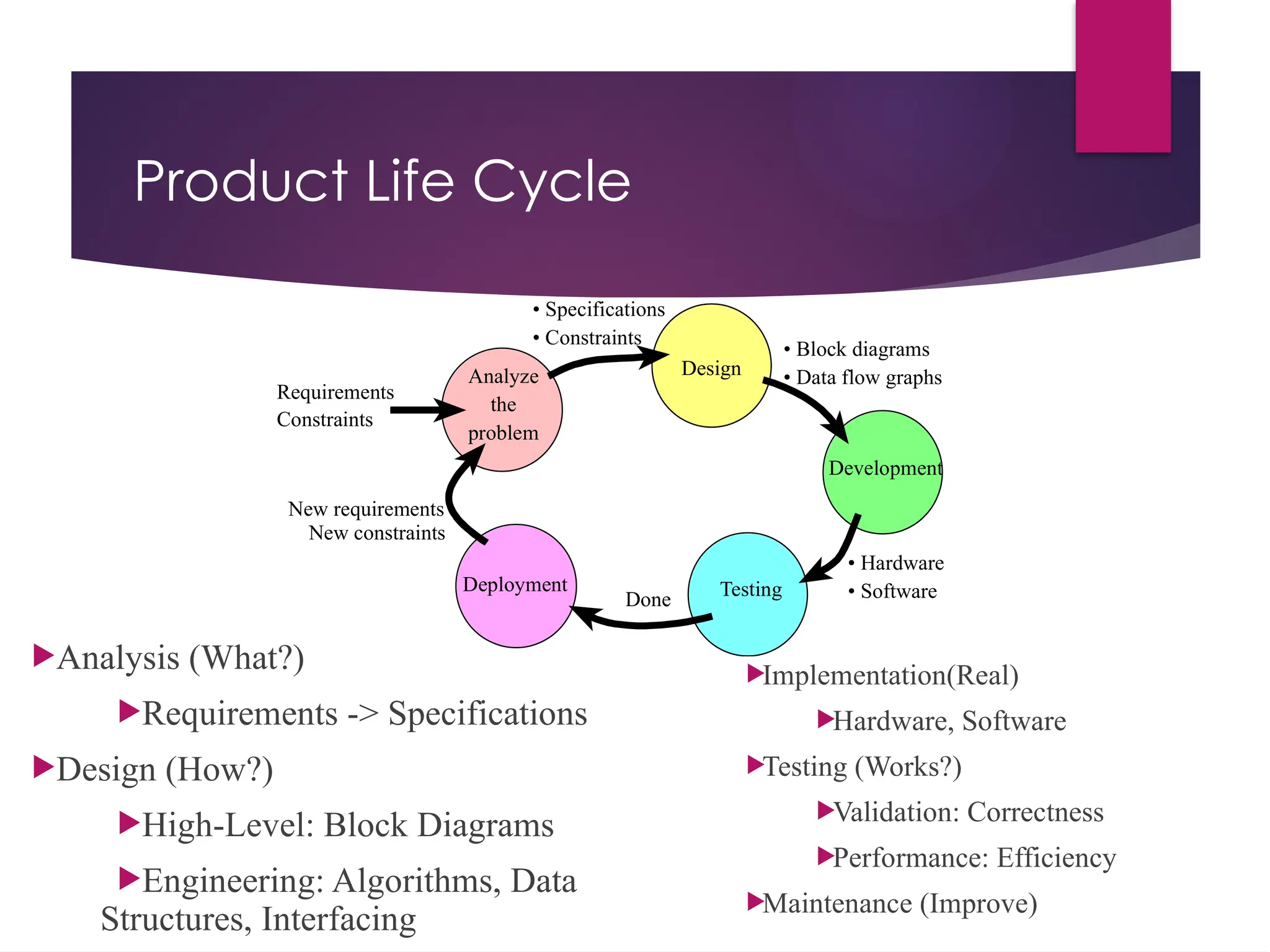
Done • Hardware • Software •Specifications • Constraints Analyze the problem Requirements Design Constraints Testing • Block diagrams • Data flow graphs Deployment New requirements New constraints Development Product Life Cycle Analysis (What?) Requirements -> Specifications Design (How?) High-Level: Block Diagrams Engineering: Algorithms, Data Structures, Interfacing Implementation(Real) Hardware, Software Testing (Works?) Validation: Correctness Performance: Efficiency Maintenance (Improve)
9.
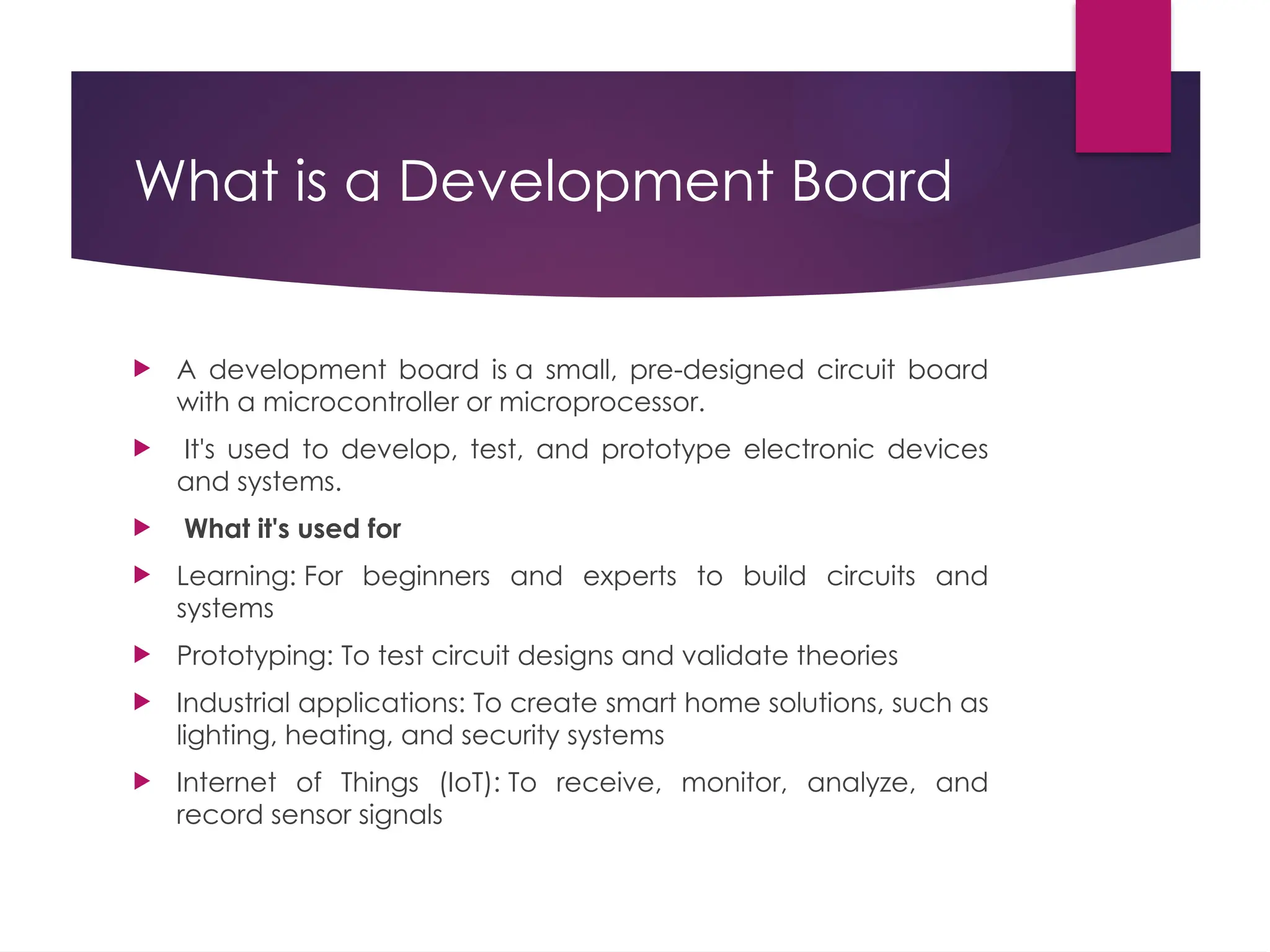
What is aDevelopment Board A development board is a small, pre-designed circuit board with a microcontroller or microprocessor. It's used to develop, test, and prototype electronic devices and systems. What it's used for Learning: For beginners and experts to build circuits and systems Prototyping: To test circuit designs and validate theories Industrial applications: To create smart home solutions, such as lighting, heating, and security systems Internet of Things (IoT): To receive, monitor, analyze, and record sensor signals
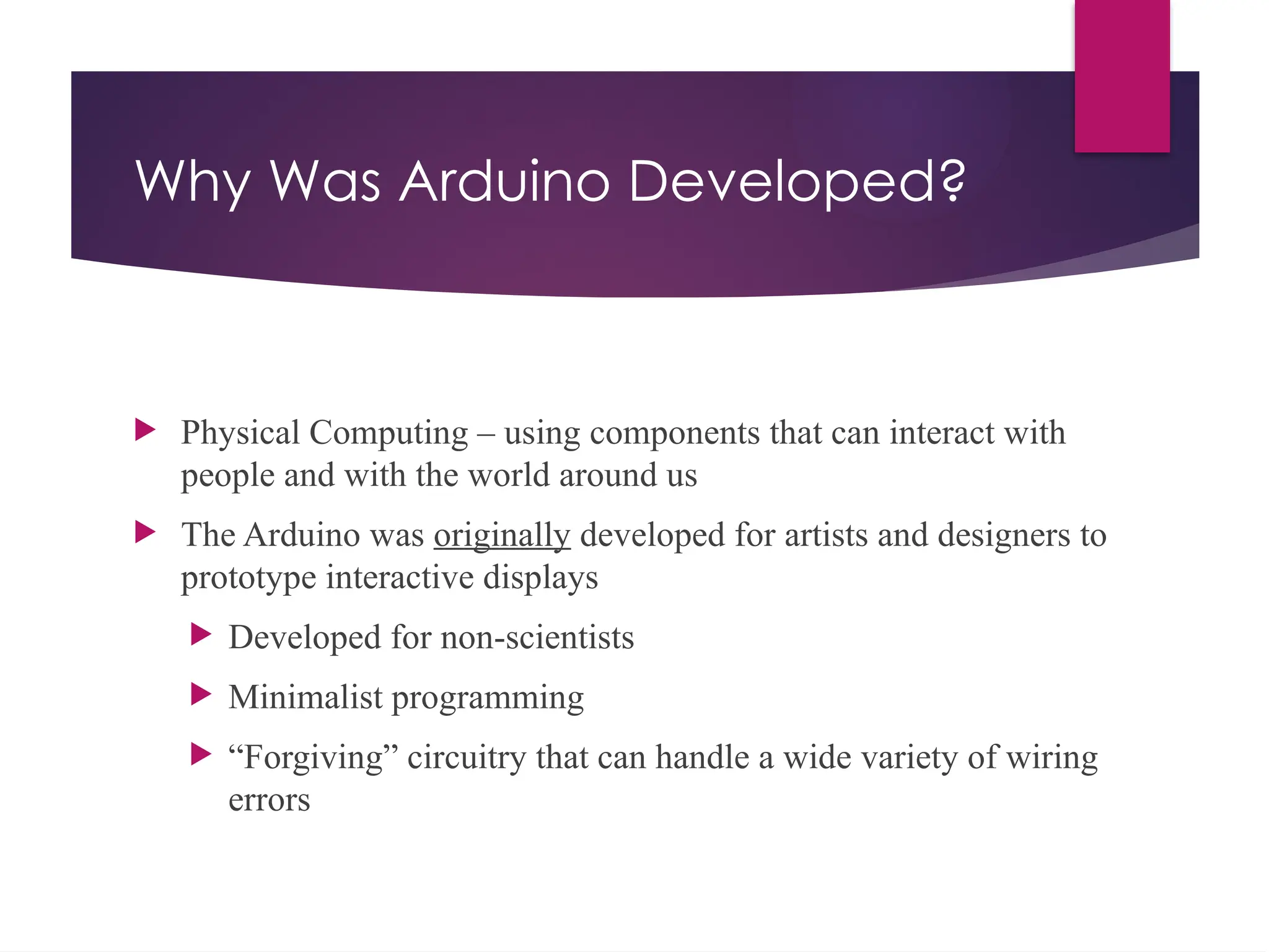
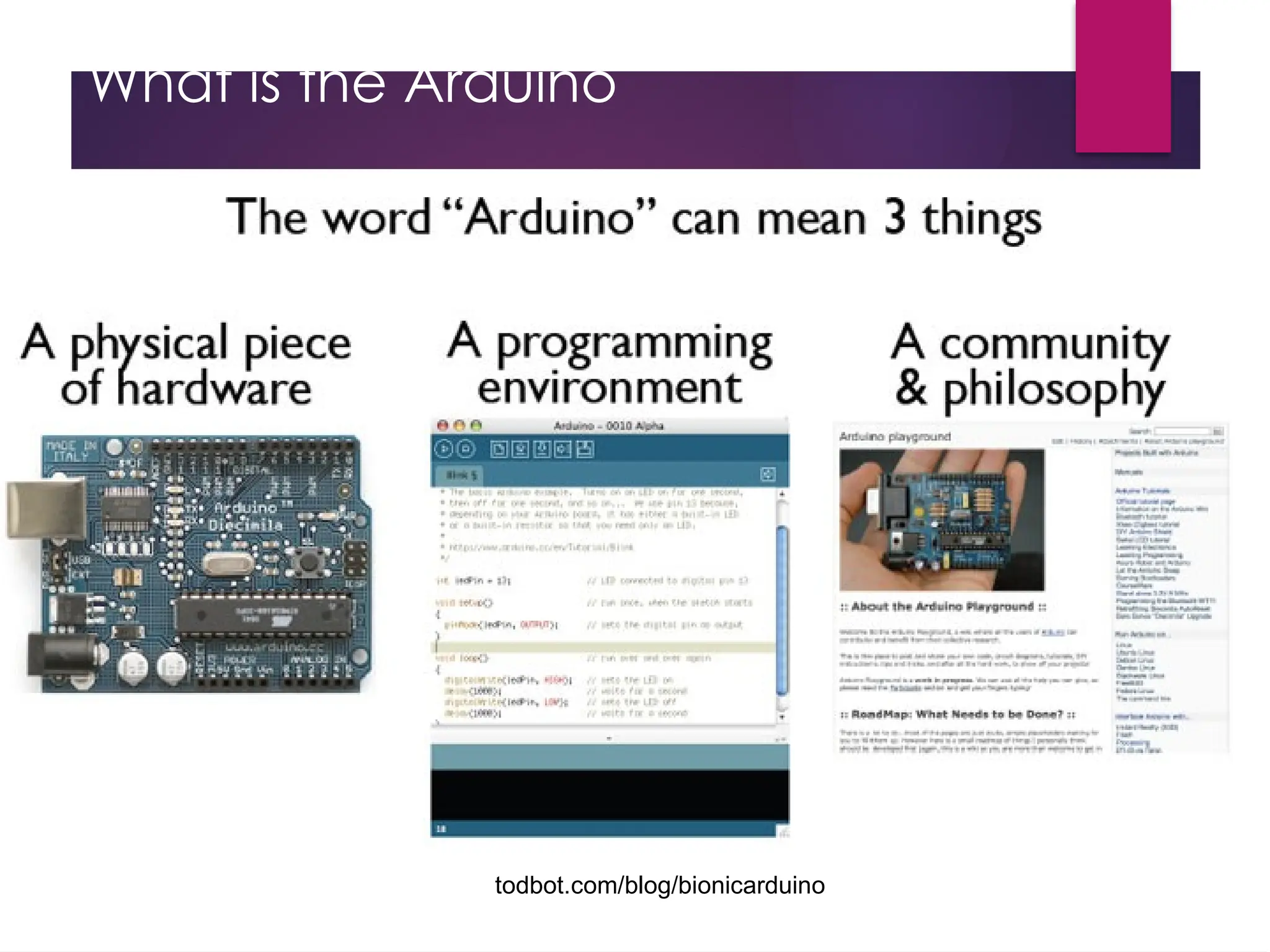
Why Was ArduinoDeveloped? Physical Computing – using components that can interact with people and with the world around us The Arduino was originally developed for artists and designers to prototype interactive displays Developed for non-scientists Minimalist programming “Forgiving” circuitry that can handle a wide variety of wiring errors
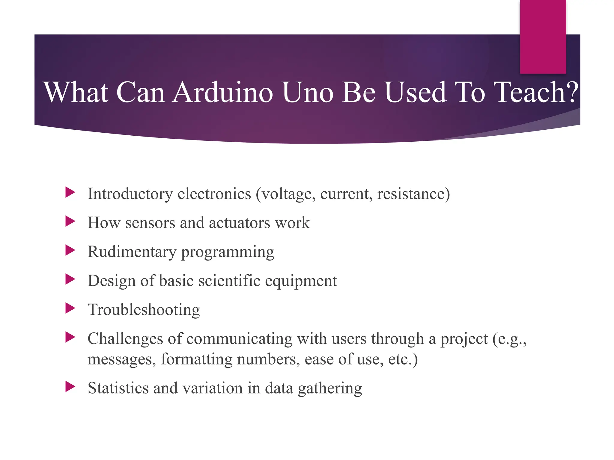
What Can ArduinoUno Be Used To Teach? Introductory electronics (voltage, current, resistance) How sensors and actuators work Rudimentary programming Design of basic scientific equipment Troubleshooting Challenges of communicating with users through a project (e.g., messages, formatting numbers, ease of use, etc.) Statistics and variation in data gathering
22.
Continuity – Isit a Circuit? The word “circuit” is derived from the circle. An Electrical Circuit must have a continuous LOOP from Power (Vcc) to Ground (GND). Continuity is important to make portions of circuits are connect. Continuity is the simplest and possibly the most important setting on your multi-meter. Sometimes we call this “ringing out” a circuit.
23.
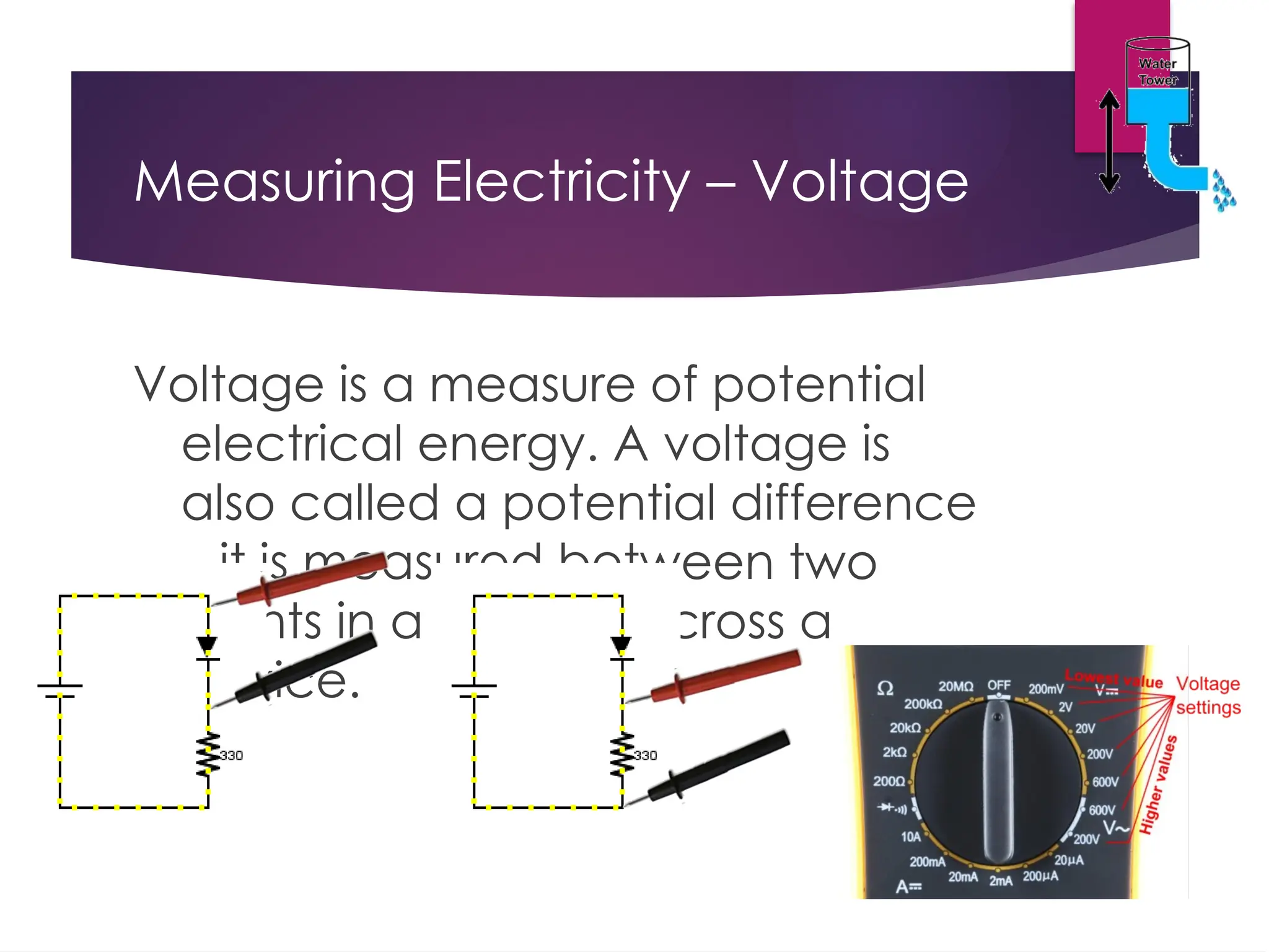
Measuring Electricity –Voltage Voltage is a measure of potential electrical energy. A voltage is also called a potential difference – it is measured between two points in a circuit – across a device.
24.
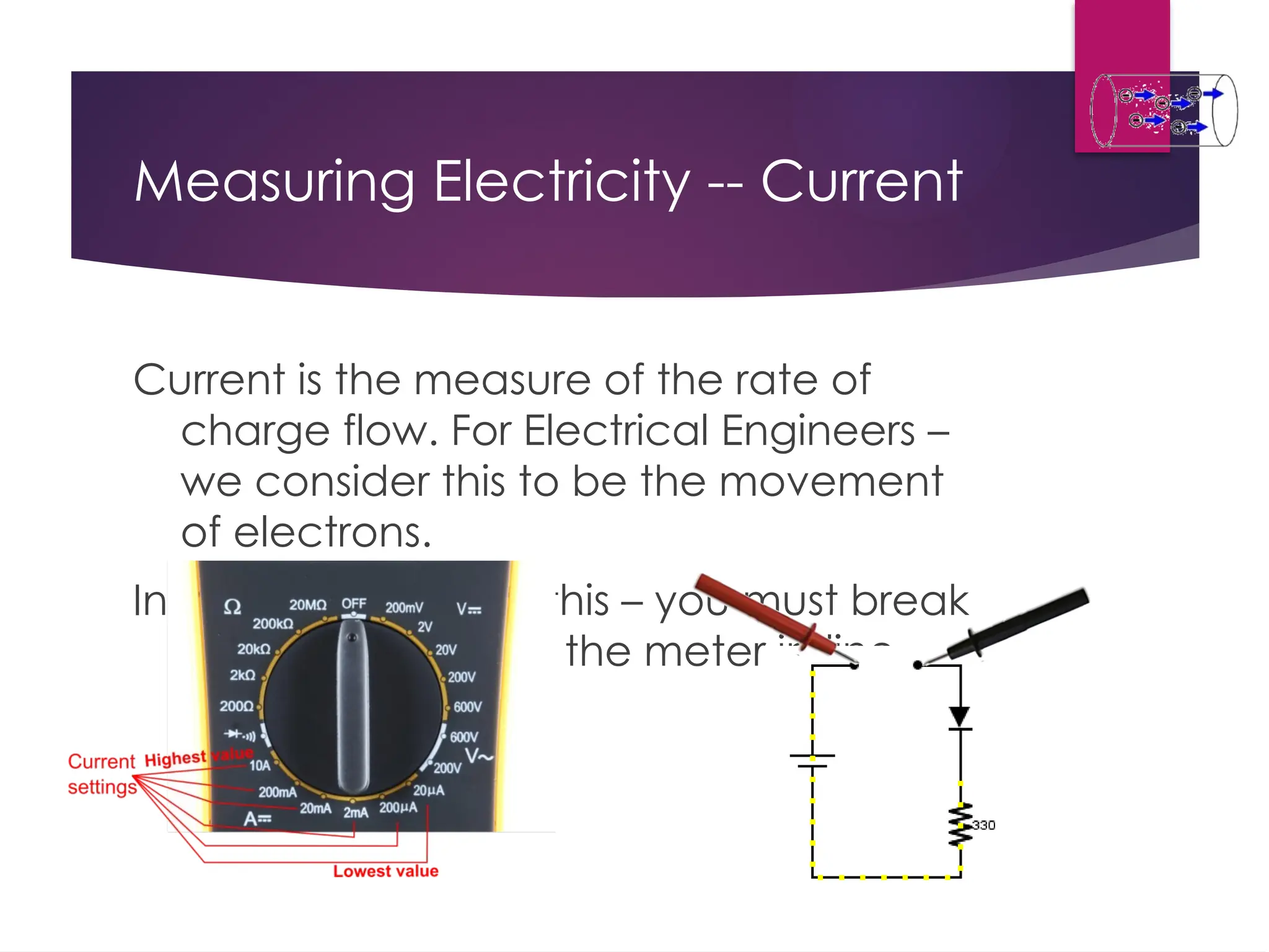
Measuring Electricity --Current Current is the measure of the rate of charge flow. For Electrical Engineers – we consider this to be the movement of electrons. In order to measure this – you must break the circuit or insert the meter in-line (series).
25.
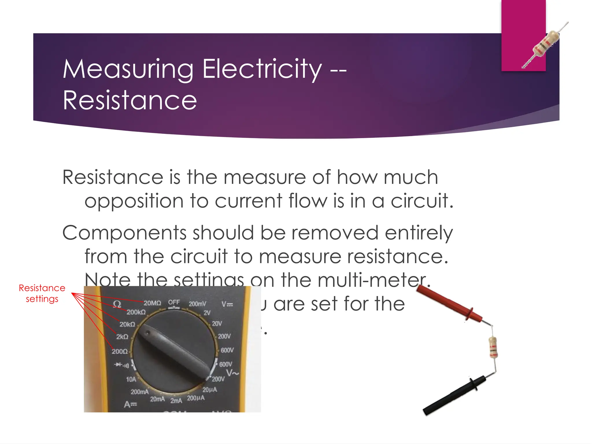
Measuring Electricity -- Resistance Resistanceis the measure of how much opposition to current flow is in a circuit. Components should be removed entirely from the circuit to measure resistance. Note the settings on the multi-meter. Make sure that you are set for the appropriate range. Resistance settings
26.
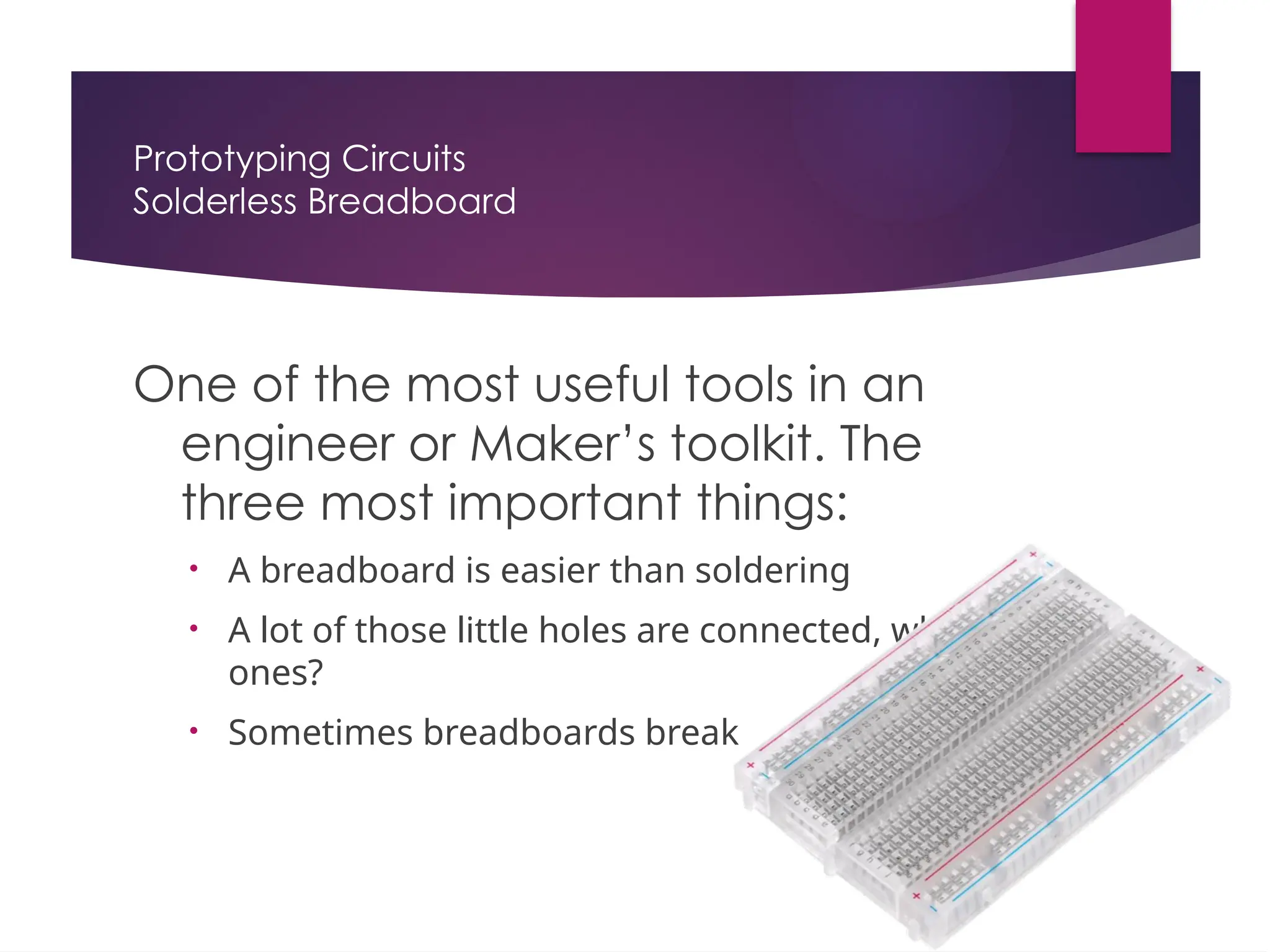
Prototyping Circuits Solderless Breadboard Oneof the most useful tools in an engineer or Maker’s toolkit. The three most important things: • A breadboard is easier than soldering • A lot of those little holes are connected, which ones? • Sometimes breadboards break
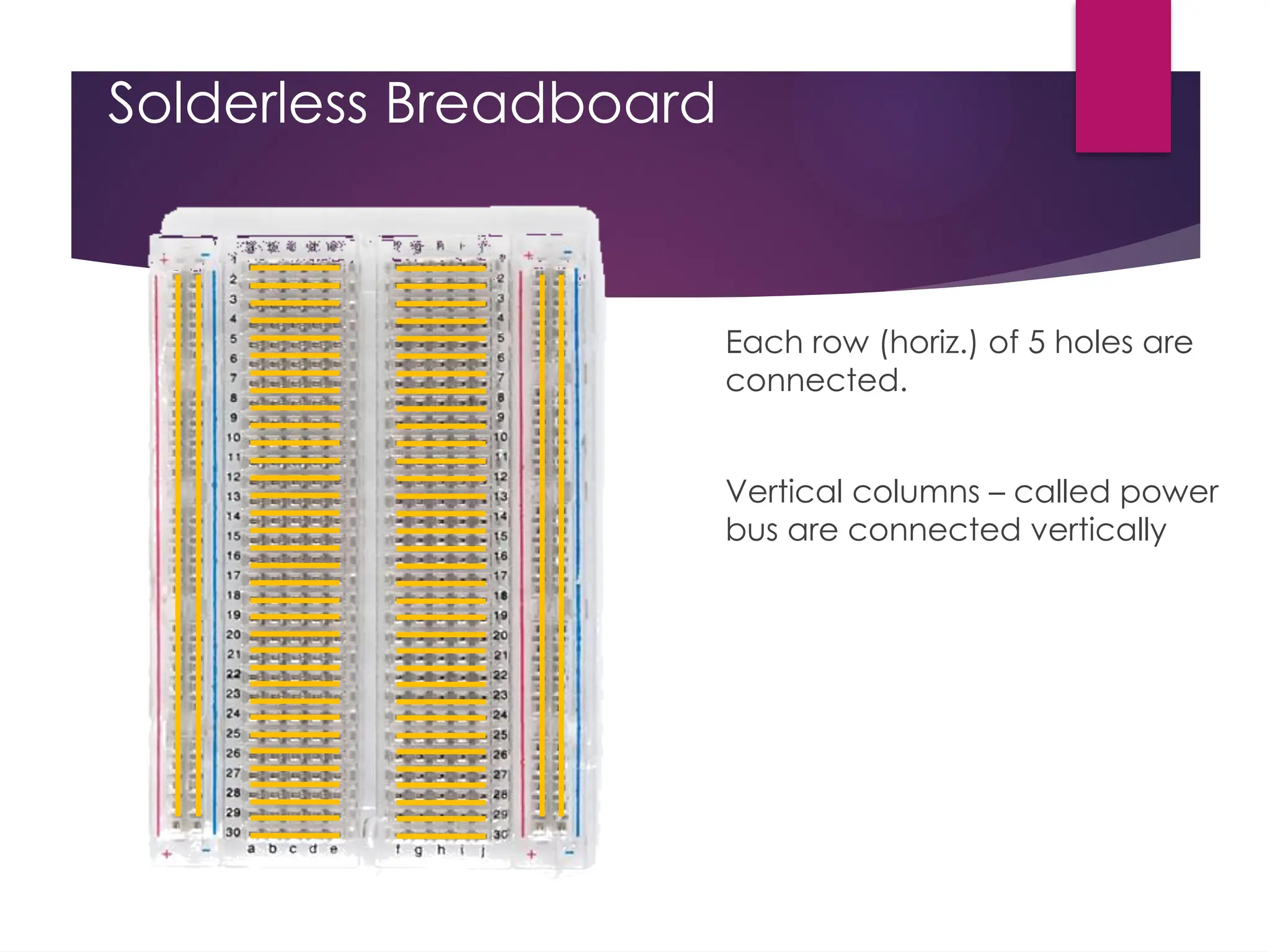
Solderless Breadboard Each row(horiz.) of 5 holes are connected. Vertical columns – called power bus are connected vertically
29.
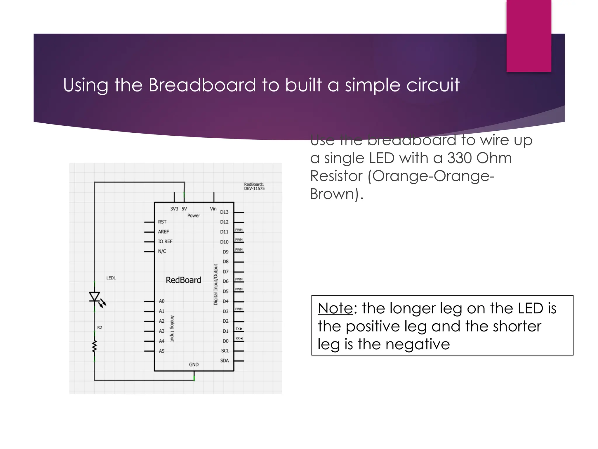
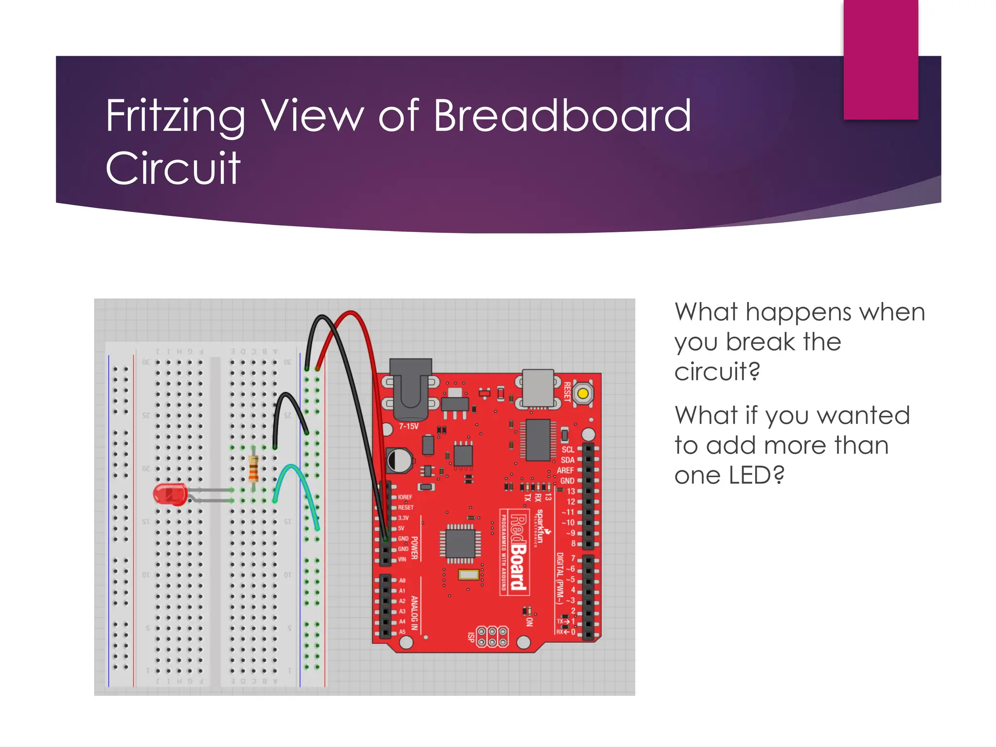
Using the Breadboardto built a simple circuit Use the breadboard to wire up a single LED with a 330 Ohm Resistor (Orange-Orange- Brown). Note: the longer leg on the LED is the positive leg and the shorter leg is the negative
30.
Fritzing View ofBreadboard Circuit What happens when you break the circuit? What if you wanted to add more than one LED?
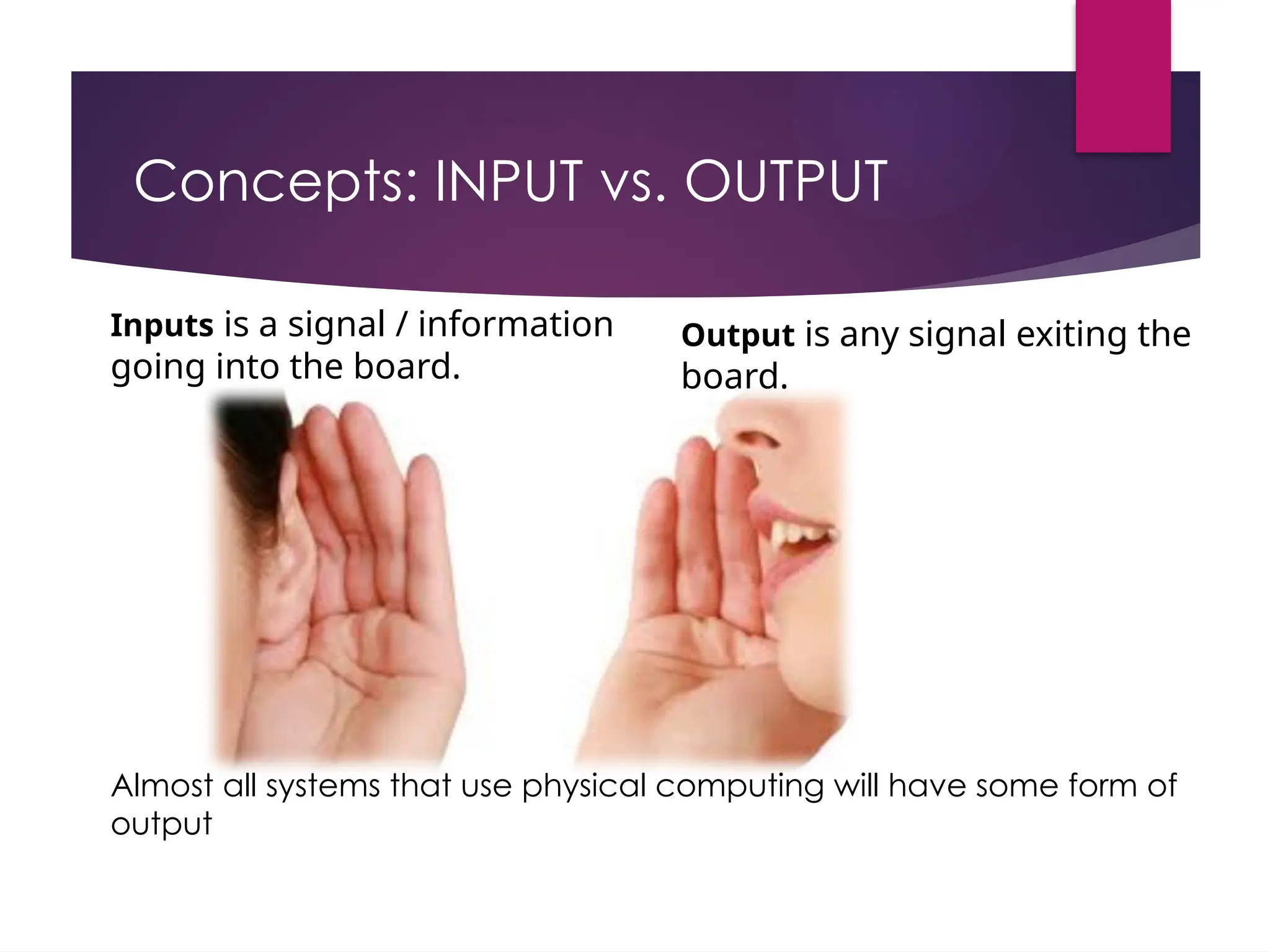
Concepts: INPUT vs.OUTPUT Inputs is a signal / information going into the board. Output is any signal exiting the board. Almost all systems that use physical computing will have some form of output
33.
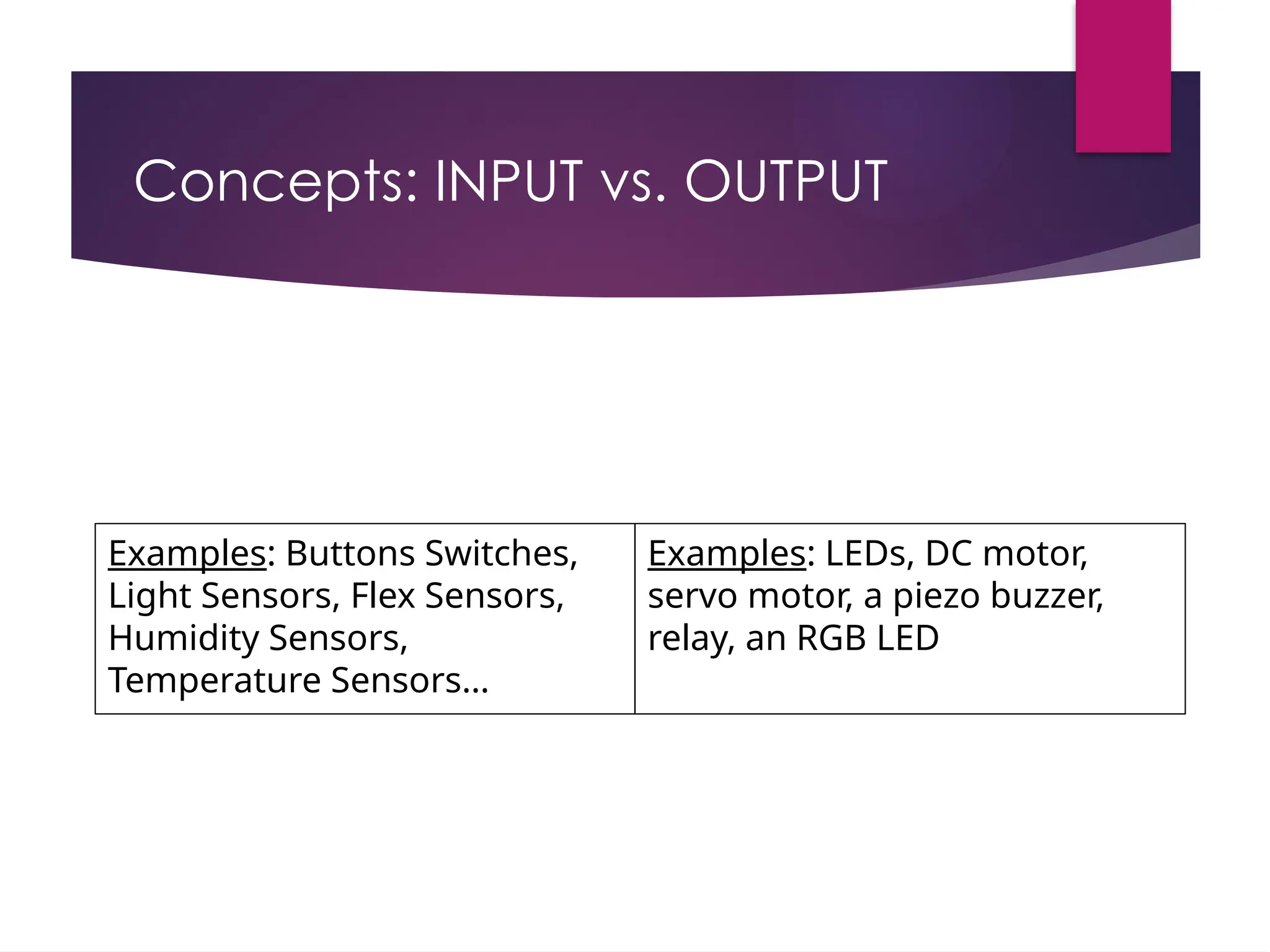
Concepts: INPUT vs.OUTPUT Examples: Buttons Switches, Light Sensors, Flex Sensors, Humidity Sensors, Temperature Sensors… Examples: LEDs, DC motor, servo motor, a piezo buzzer, relay, an RGB LED
34.
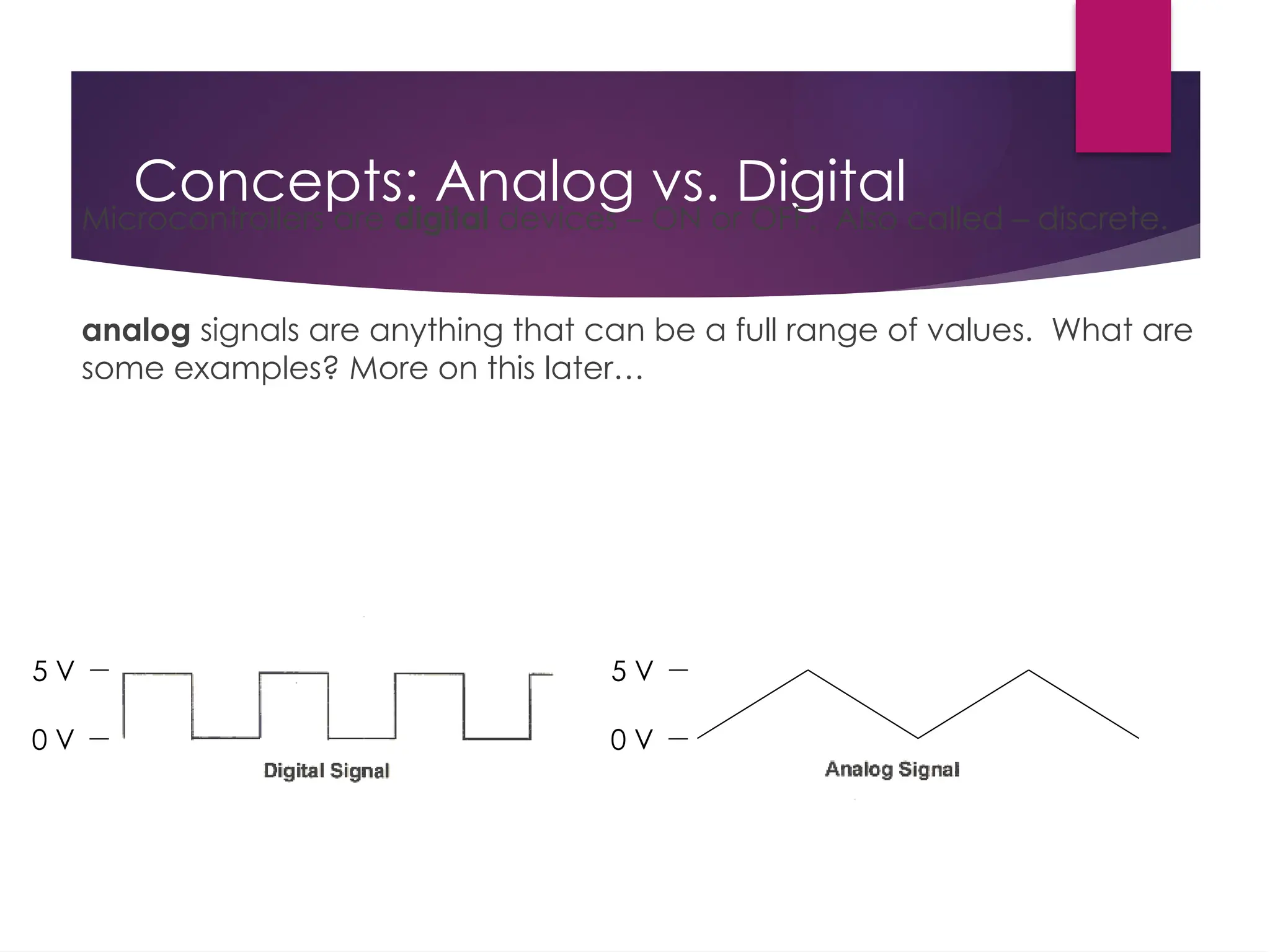
Concepts: Analog vs.Digital Microcontrollers are digital devices – ON or OFF. Also called – discrete. analog signals are anything that can be a full range of values. What are some examples? More on this later… 5 V 0 V 5 V 0 V
35.
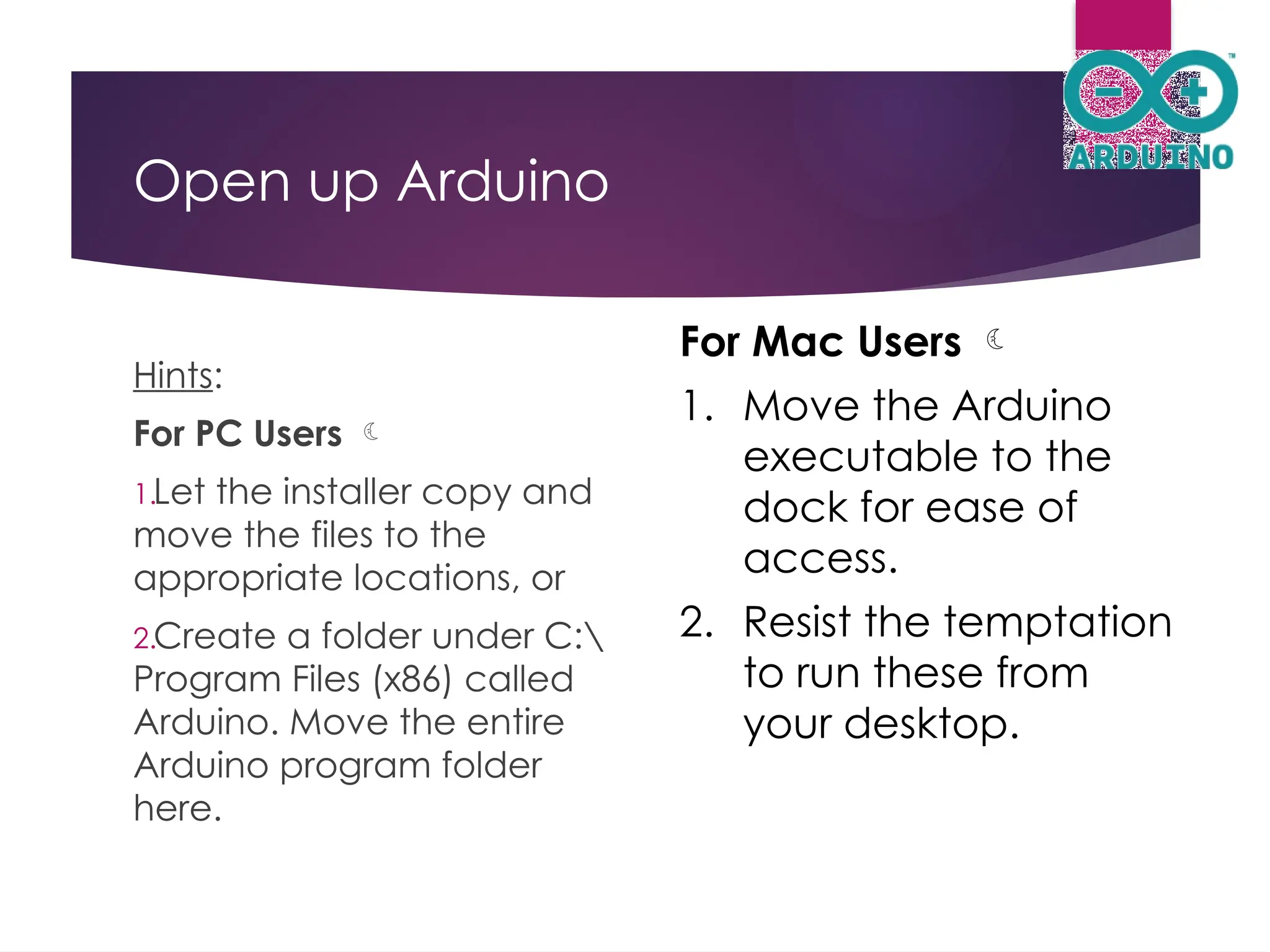
Open up Arduino Hints: ForPC Users 1.Let the installer copy and move the files to the appropriate locations, or 2.Create a folder under C: Program Files (x86) called Arduino. Move the entire Arduino program folder here. For Mac Users 1. Move the Arduino executable to the dock for ease of access. 2. Resist the temptation to run these from your desktop.
36.
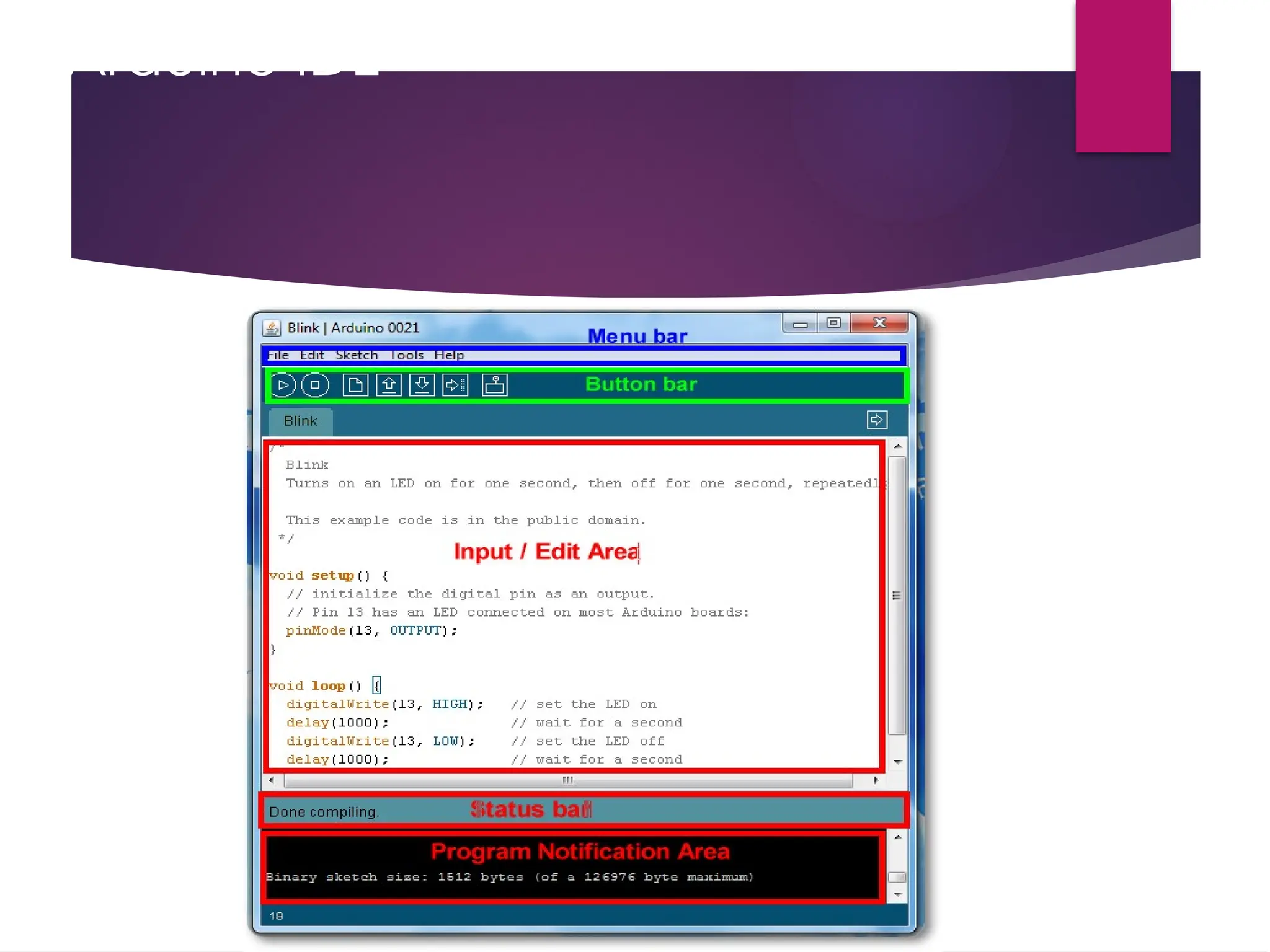
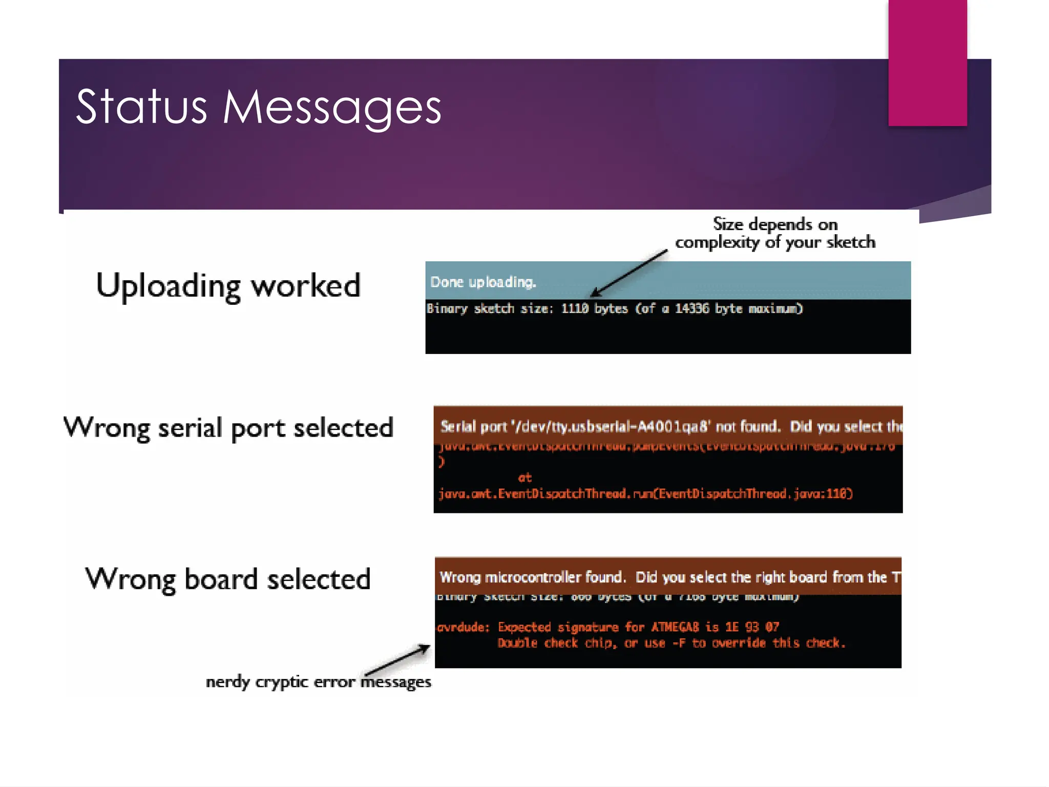
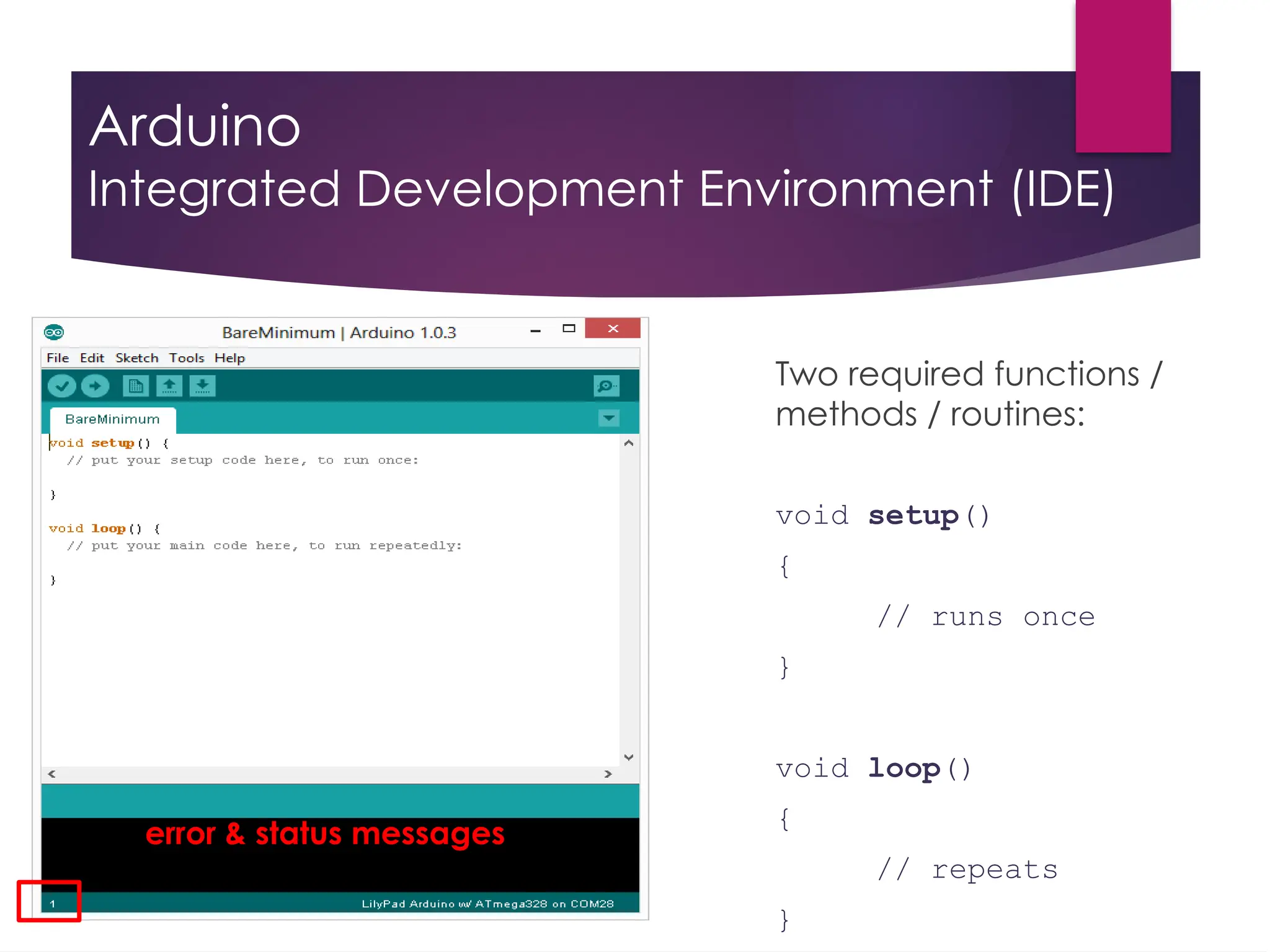
Arduino Integrated Development Environment(IDE) Two required functions / methods / routines: void setup() { // runs once } void loop() { // repeats } error & status messages
37.
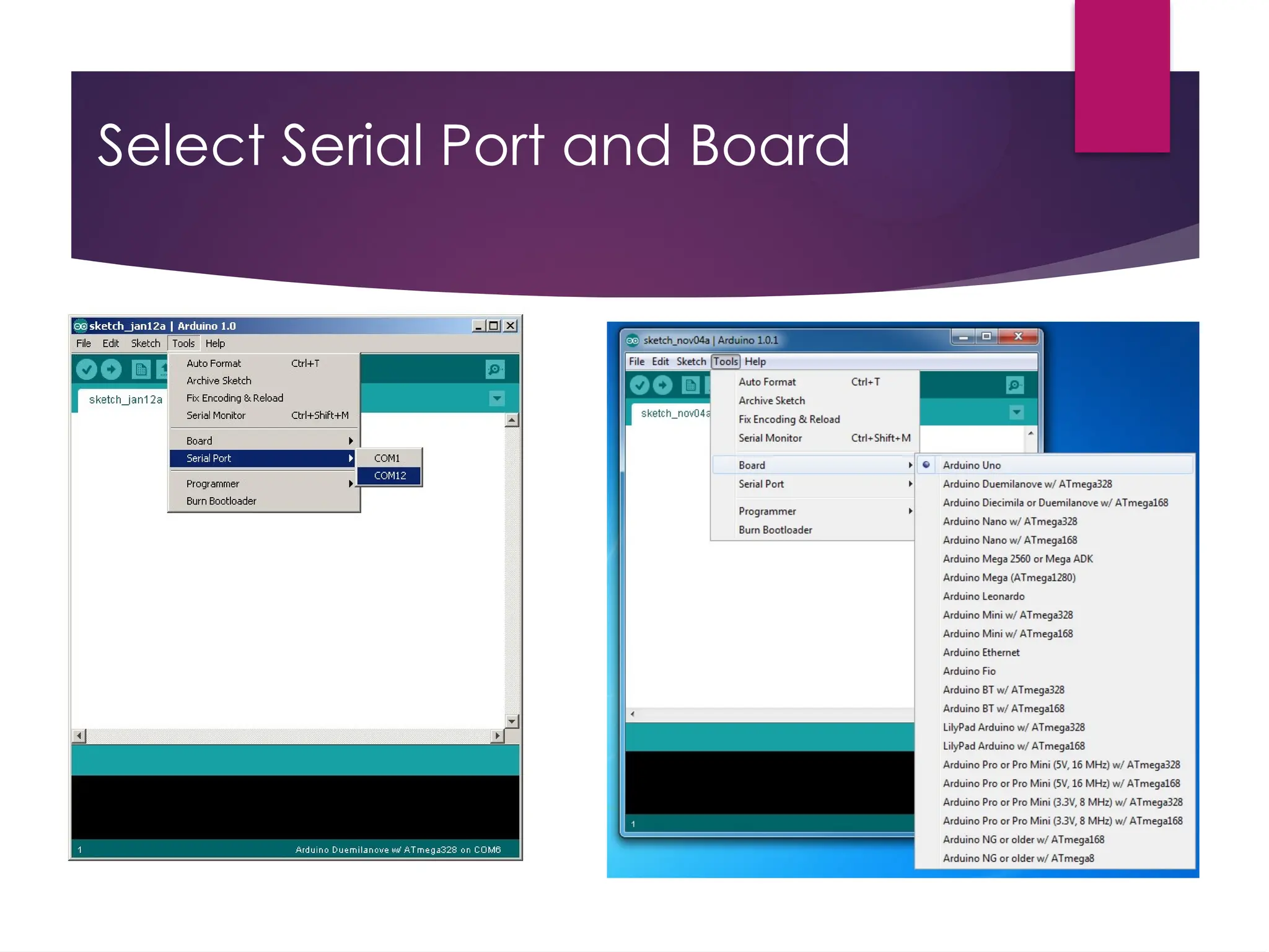
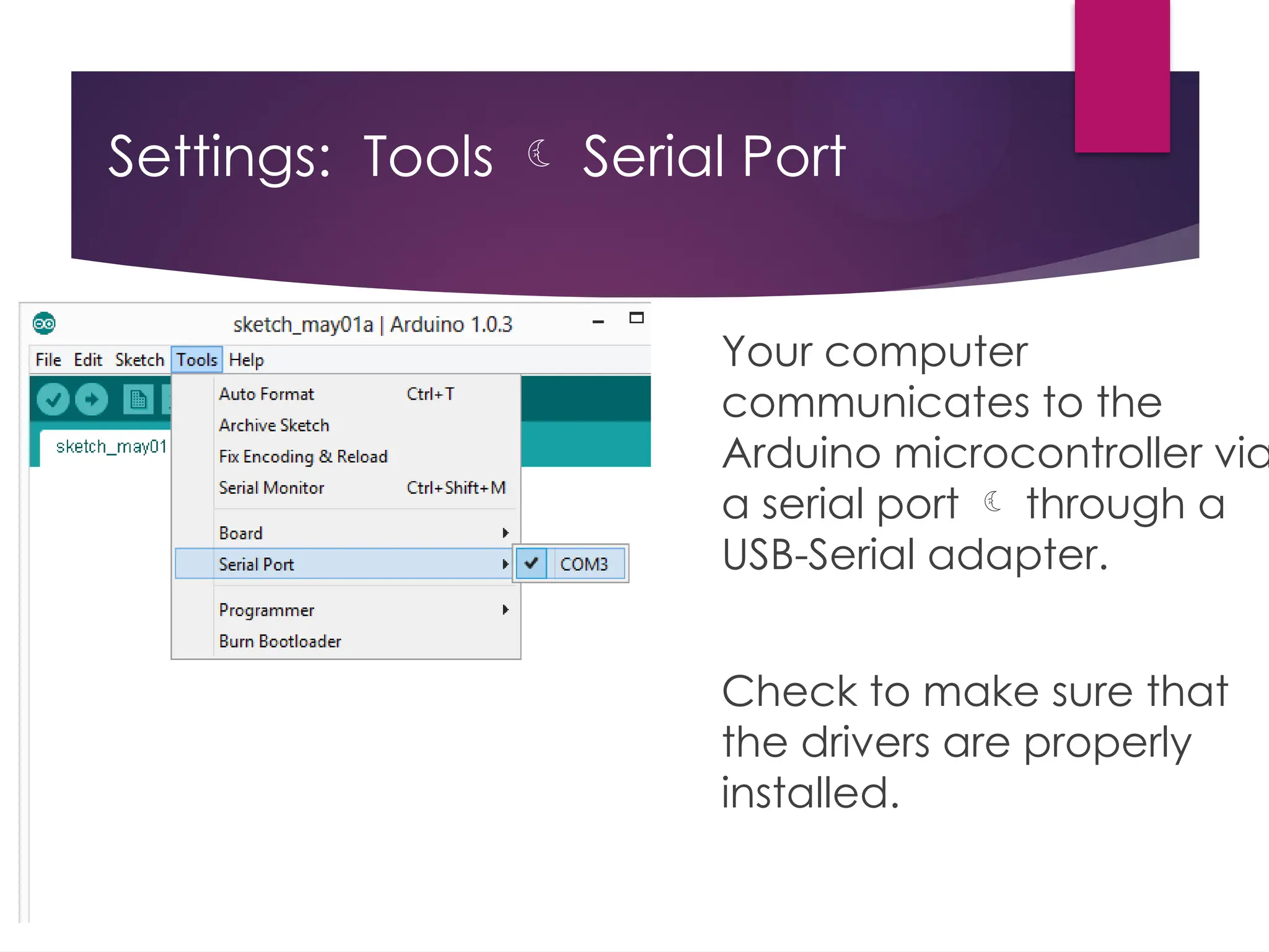
Settings: Tools Serial Port Your computer communicates to the Arduino microcontroller via a serial port through a USB-Serial adapter. Check to make sure that the drivers are properly installed.
38.
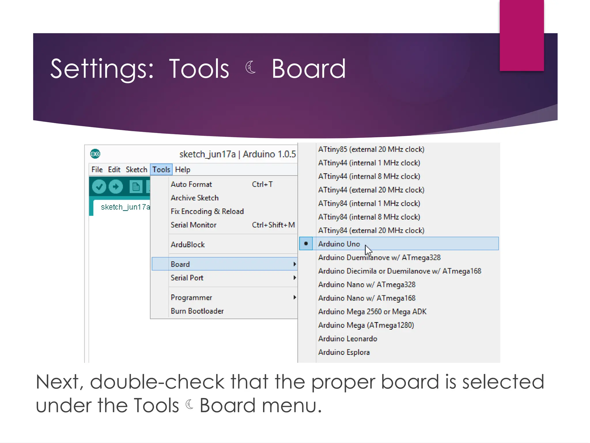
Settings: Tools Board Next, double-check that the proper board is selected under the ToolsBoard menu.
39.
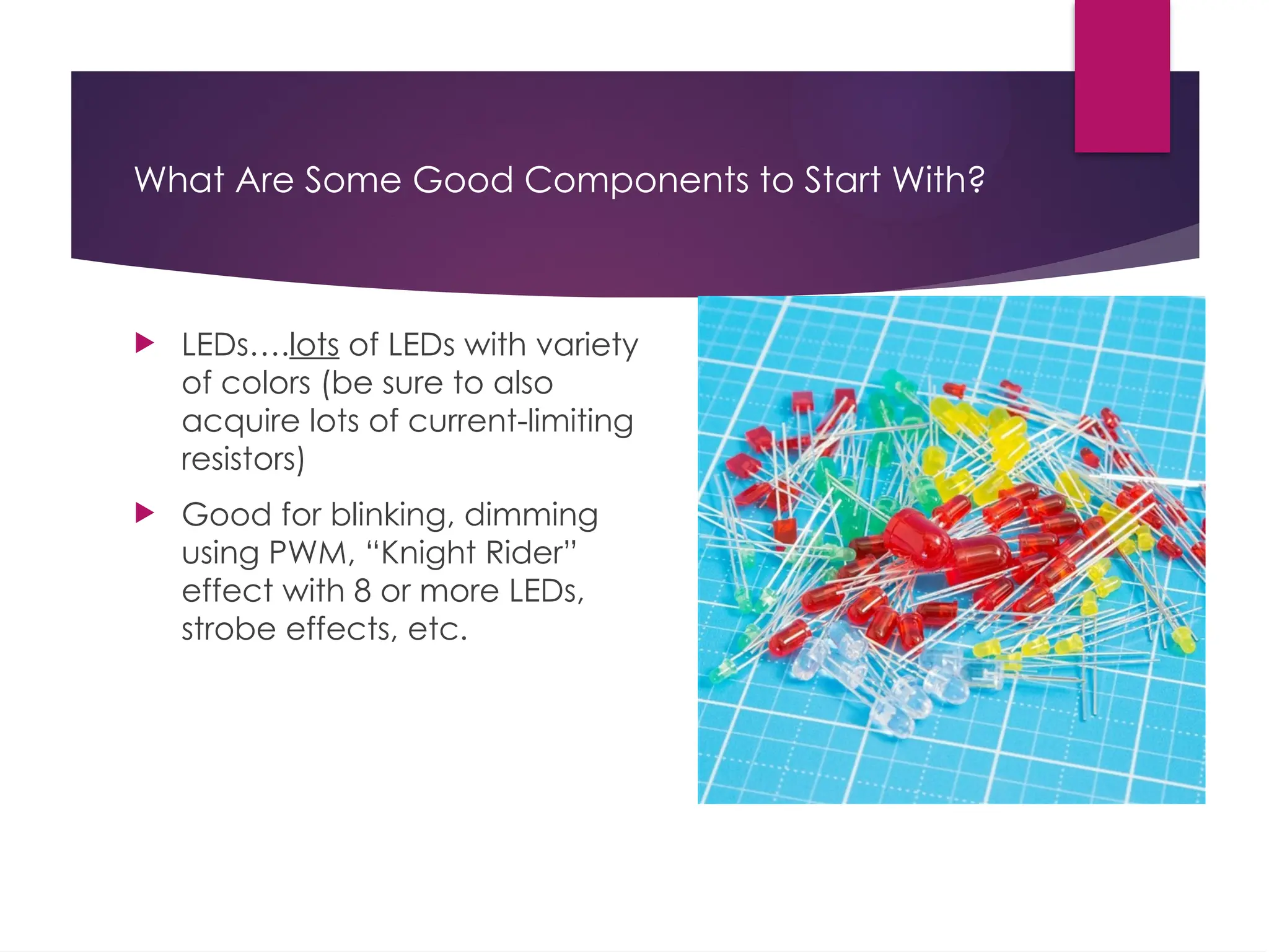
What Are SomeGood Components to Start With? LEDs….lots of LEDs with variety of colors (be sure to also acquire lots of current-limiting resistors) Good for blinking, dimming using PWM, “Knight Rider” effect with 8 or more LEDs, strobe effects, etc.
40.
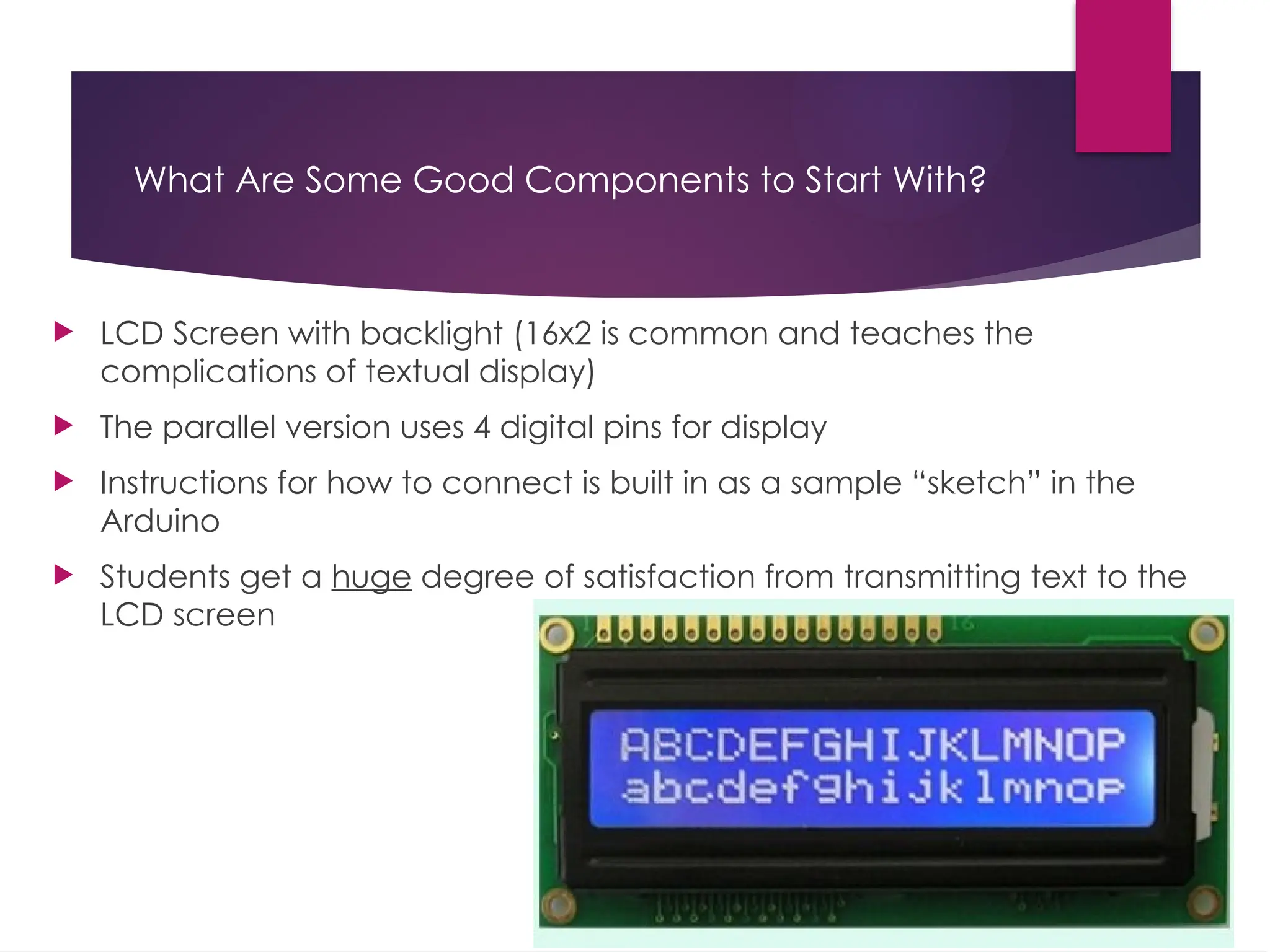
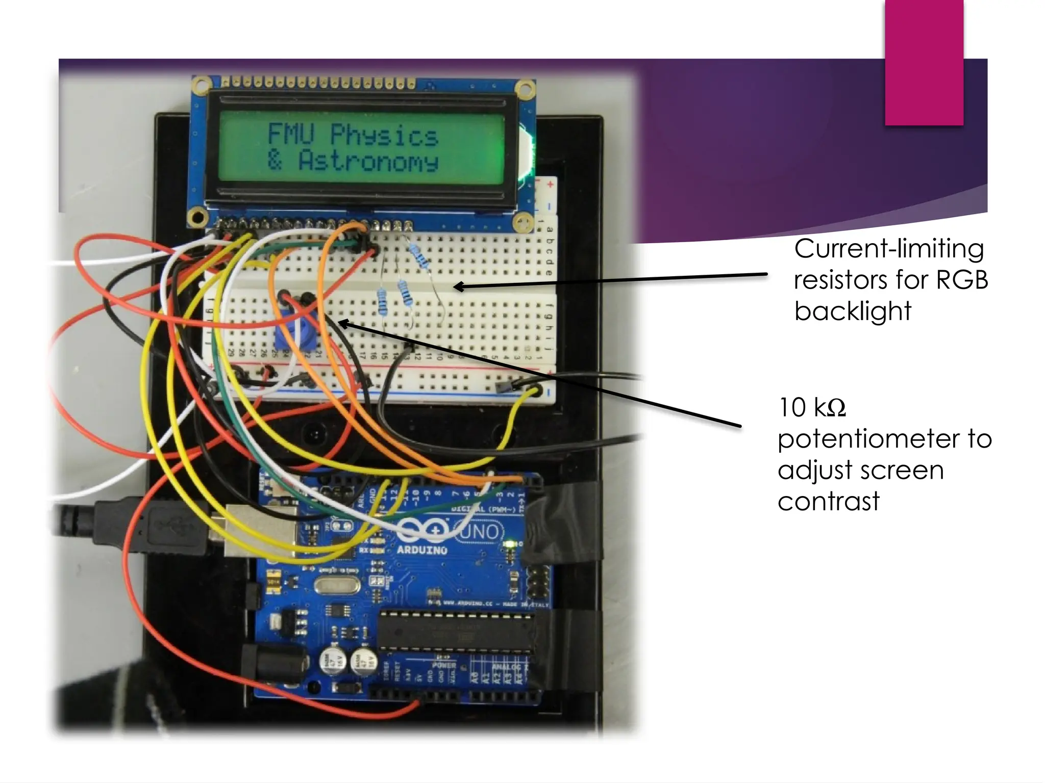
What Are SomeGood Components to Start With? LCD Screen with backlight (16x2 is common and teaches the complications of textual display) The parallel version uses 4 digital pins for display Instructions for how to connect is built in as a sample “sketch” in the Arduino Students get a huge degree of satisfaction from transmitting text to the LCD screen
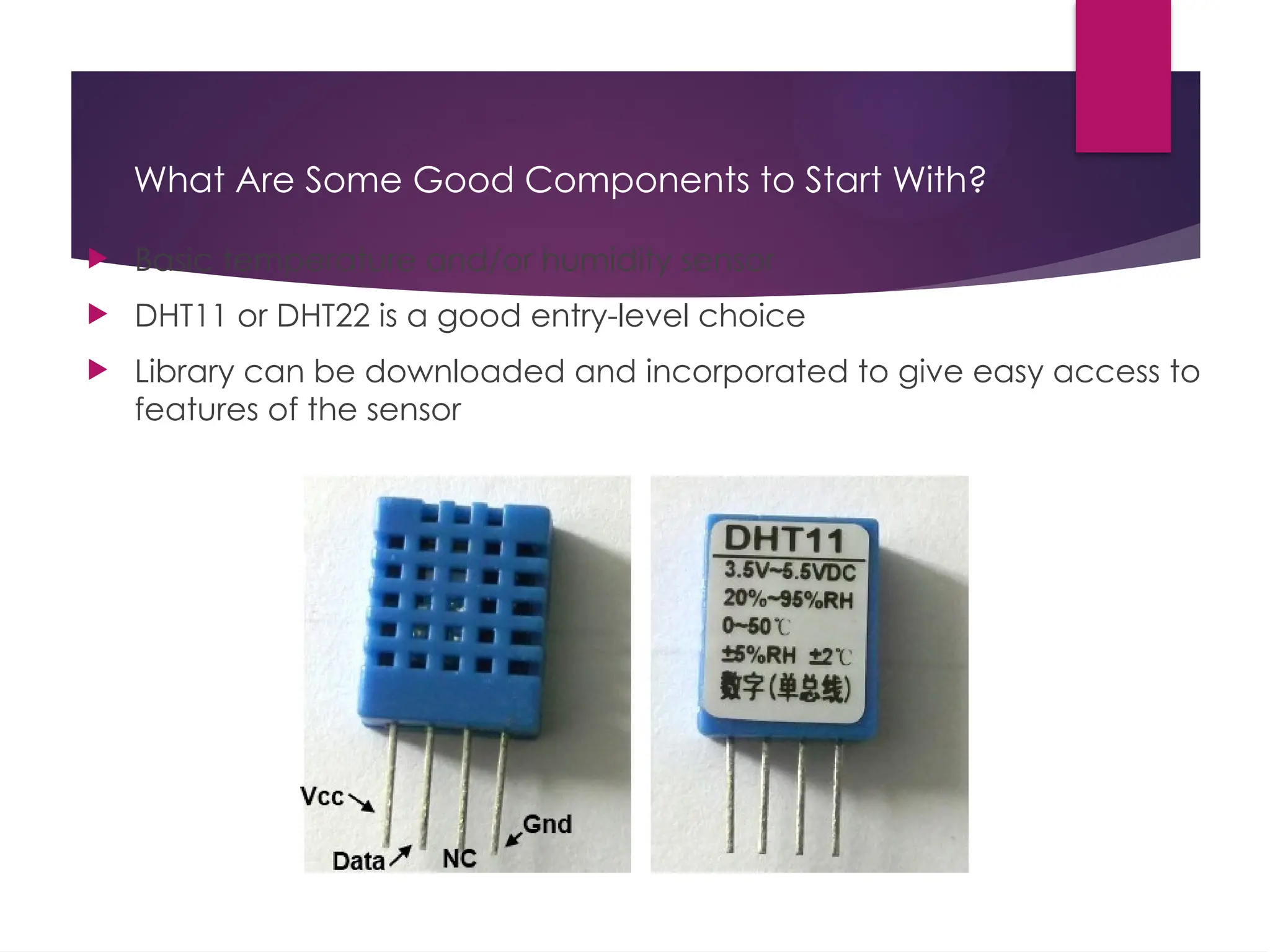
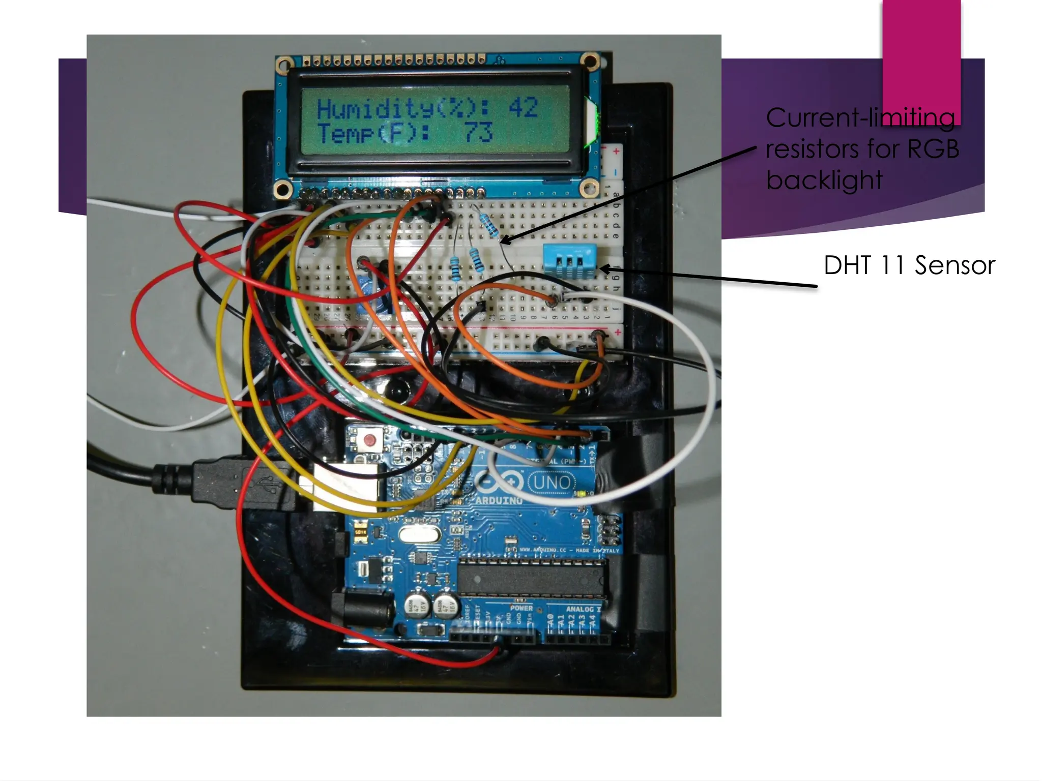
What Are SomeGood Components to Start With? Basic temperature and/or humidity sensor DHT11 or DHT22 is a good entry-level choice Library can be downloaded and incorporated to give easy access to features of the sensor
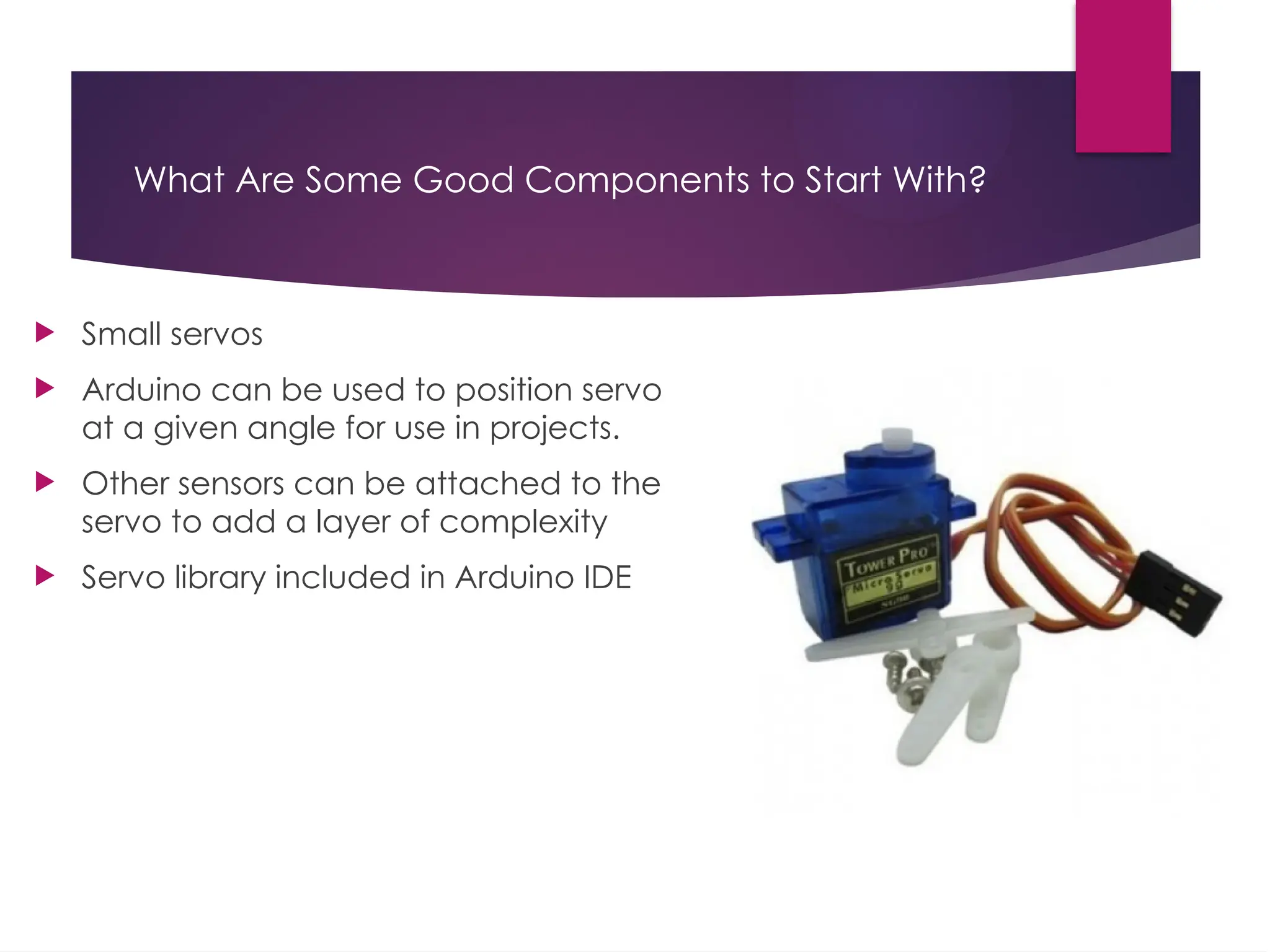
What Are SomeGood Components to Start With? Small servos Arduino can be used to position servo at a given angle for use in projects. Other sensors can be attached to the servo to add a layer of complexity Servo library included in Arduino IDE
45.
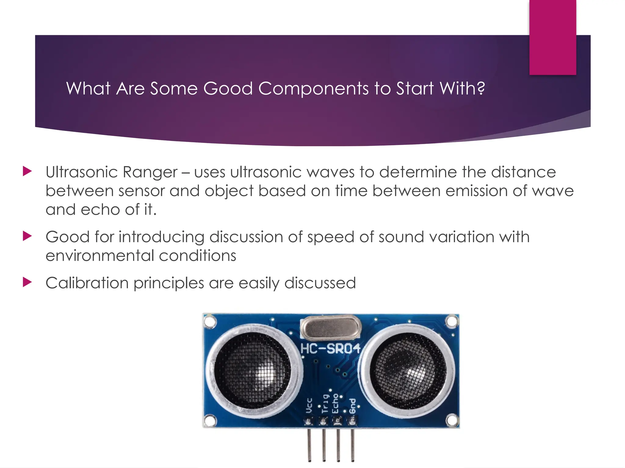
What Are SomeGood Components to Start With? Ultrasonic Ranger – uses ultrasonic waves to determine the distance between sensor and object based on time between emission of wave and echo of it. Good for introducing discussion of speed of sound variation with environmental conditions Calibration principles are easily discussed
46.
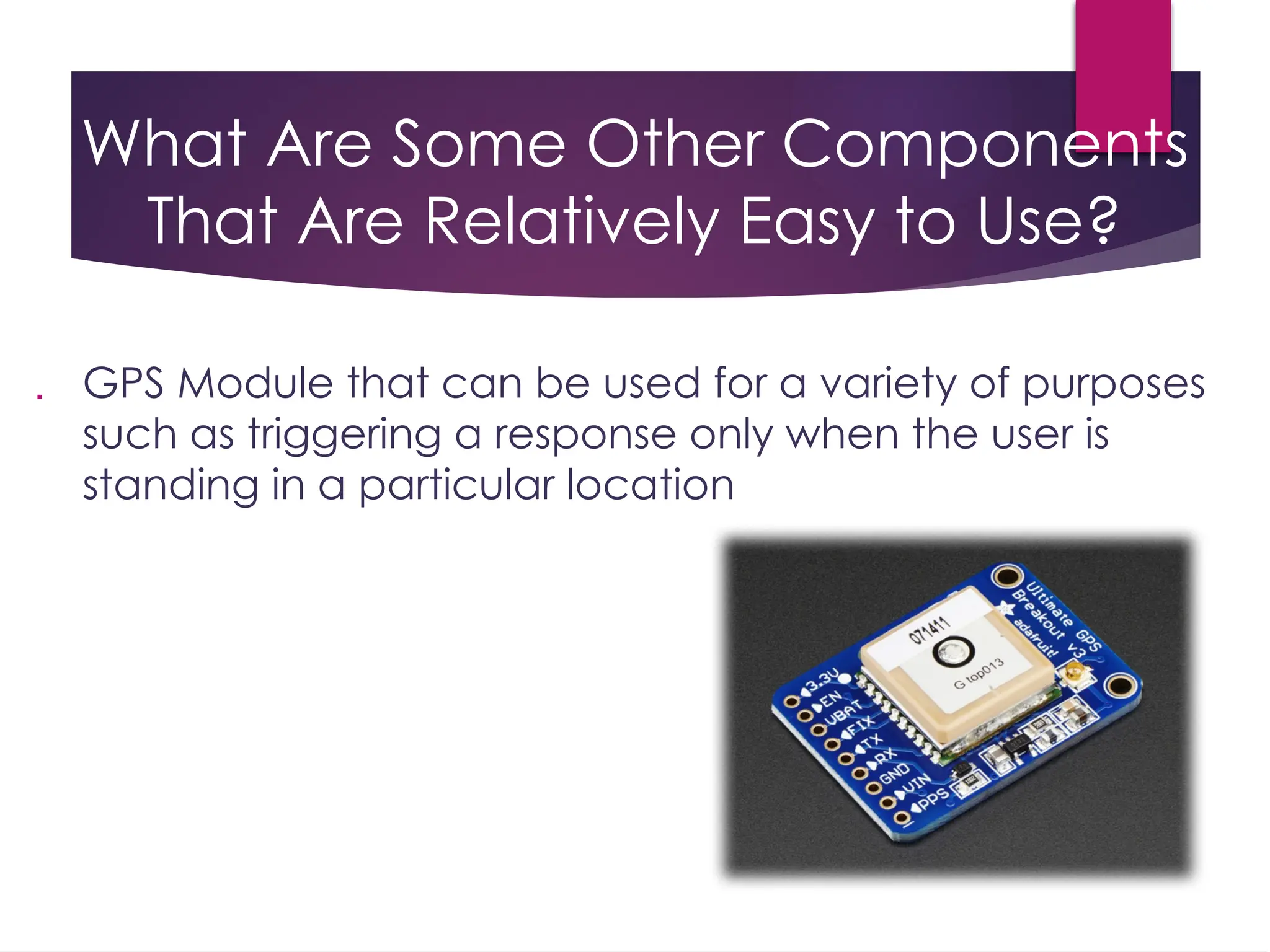
What Are SomeOther Components That Are Relatively Easy to Use? GPS Module that can be used for a variety of purposes such as triggering a response only when the user is standing in a particular location
47.
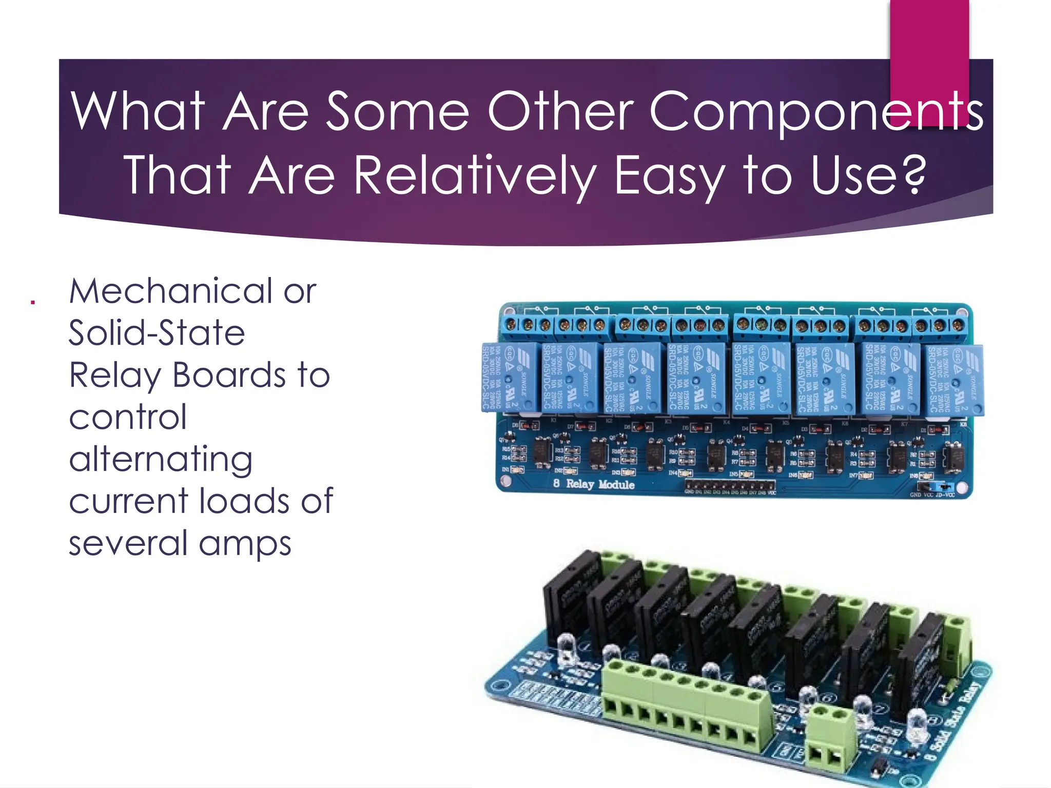
What Are SomeOther Components That Are Relatively Easy to Use? Mechanical or Solid-State Relay Boards to control alternating current loads of several amps
48.
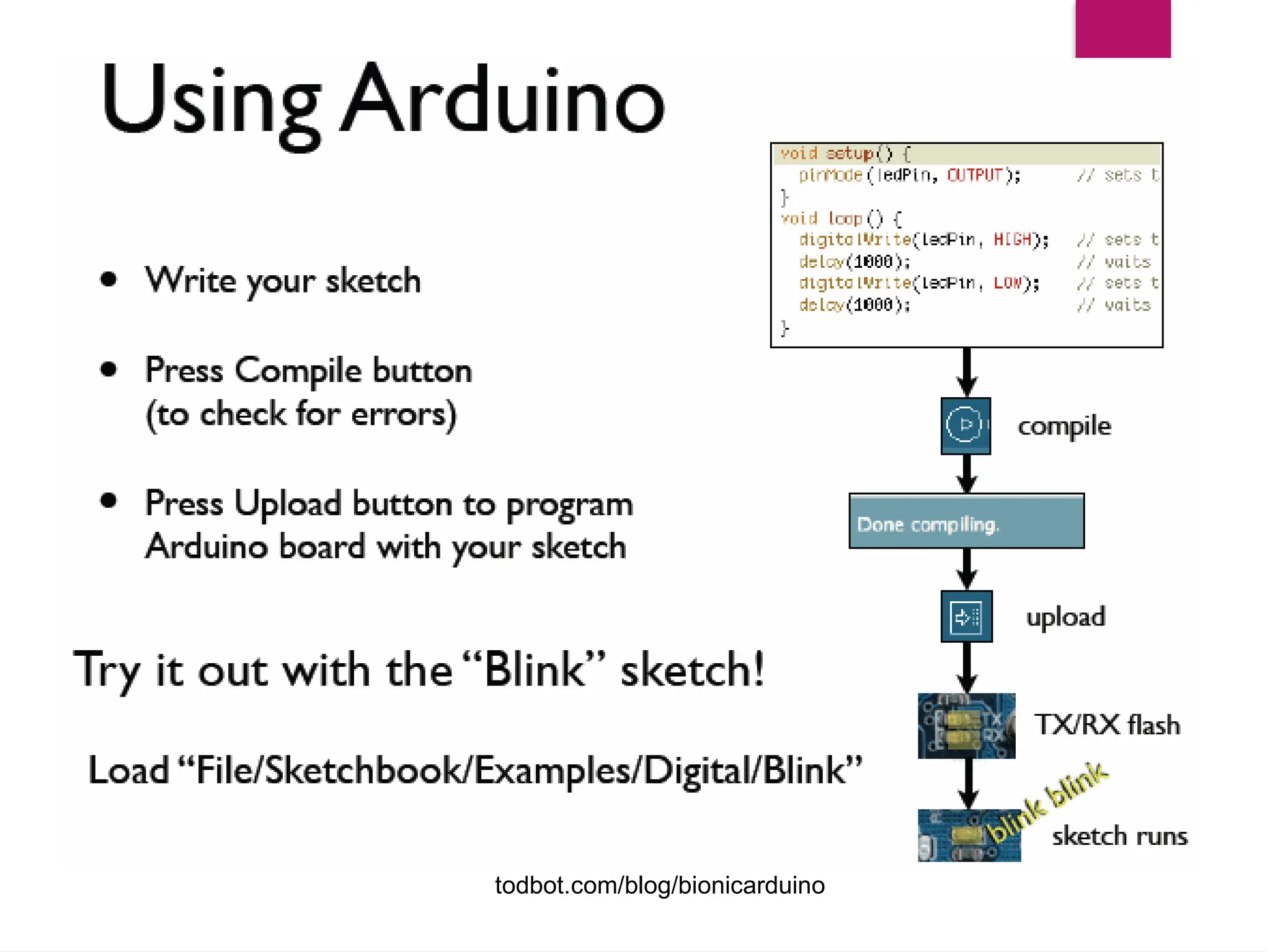
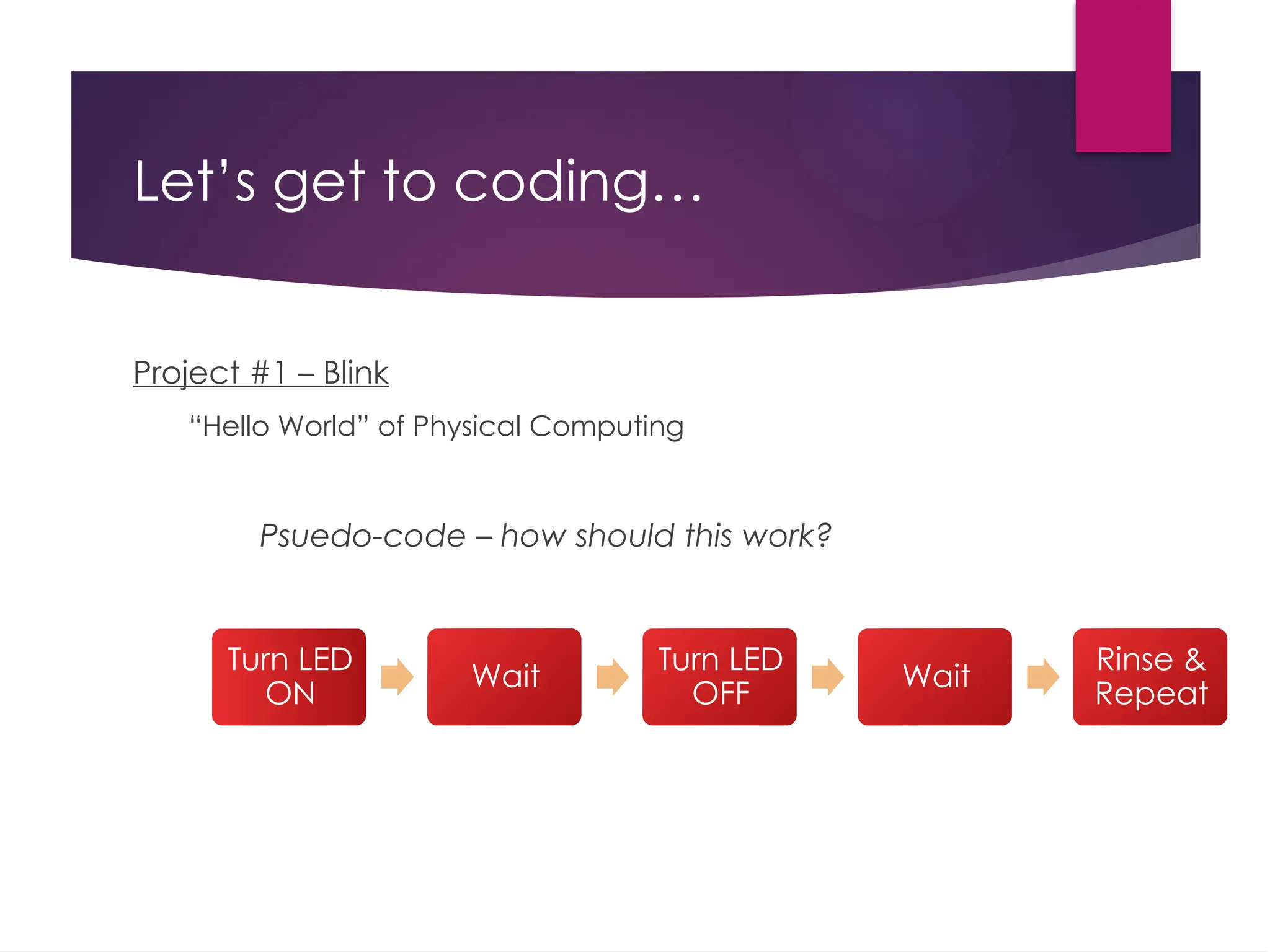
Let’s get tocoding… Project #1 – Blink “Hello World” of Physical Computing Psuedo-code – how should this work? Turn LED ON Wait Turn LED OFF Wait Rinse & Repeat
49.
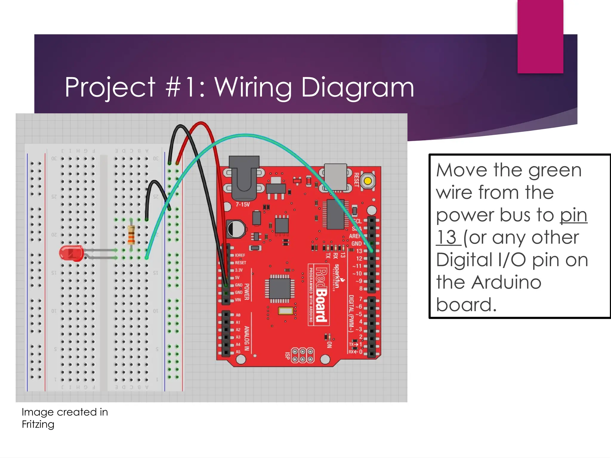
Project #1: WiringDiagram Move the green wire from the power bus to pin 13 (or any other Digital I/O pin on the Arduino board. Image created in Fritzing
50.
A few simplechallenges Let’s make LED#13 blink! Challenge 1a – blink with a 200 ms second interval. Challenge 1b – blink to mimic a heartbeat Challenge 1c – find the fastest blink that the human eye can still detect… 1 ms delay? 2 ms delay? 3 ms delay???
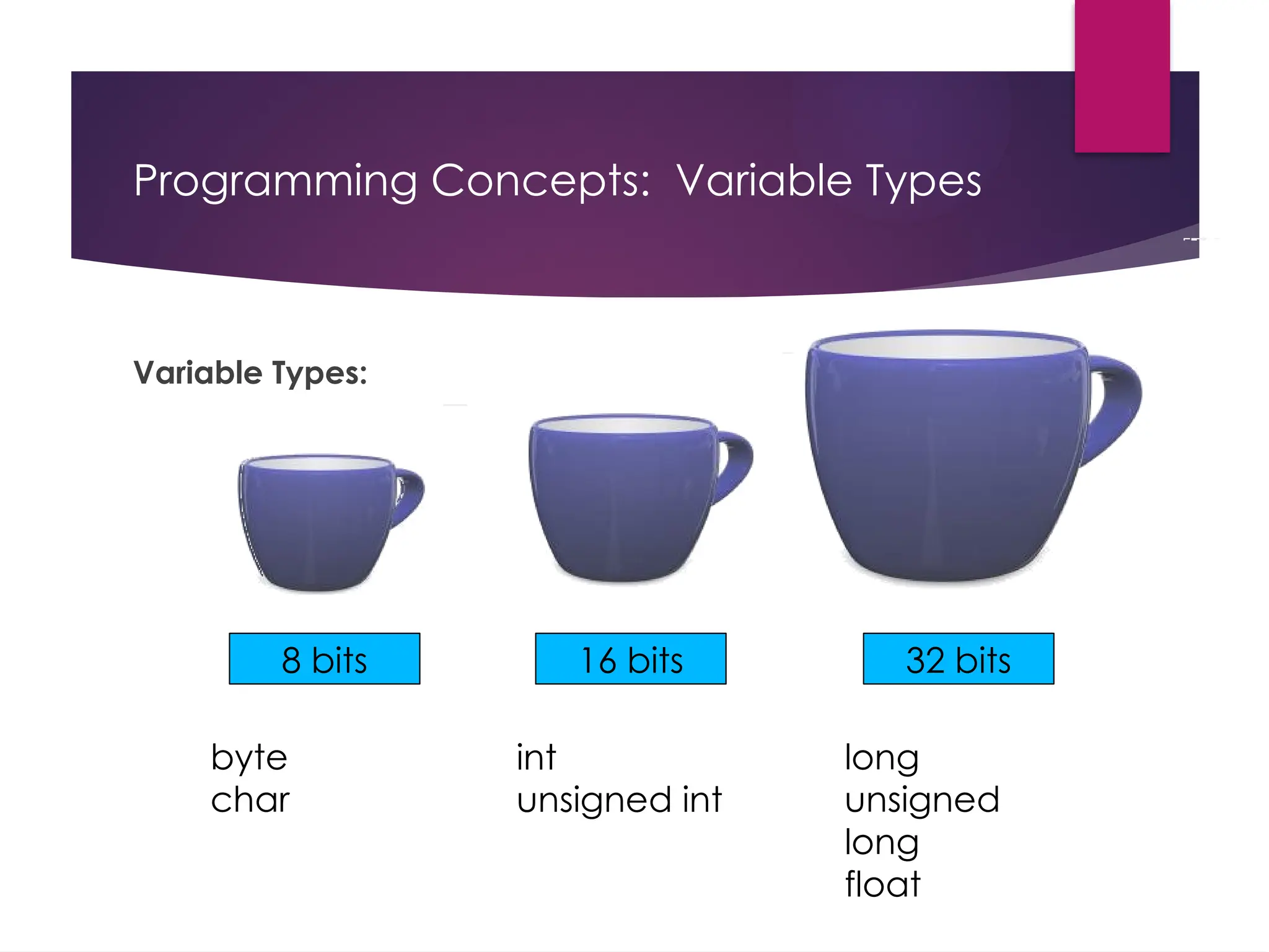
Programming Concepts: VariableTypes Variable Types: 8 bits 16 bits 32 bits byte char int unsigned int long unsigned long float
54.
Fading in andFading Out (Analog or Digital?) A few pins on the Arduino allow for us to modify the output to mimic an analog signal. This is done by a technique called: Pulse Width Modulation (PWM)
55.
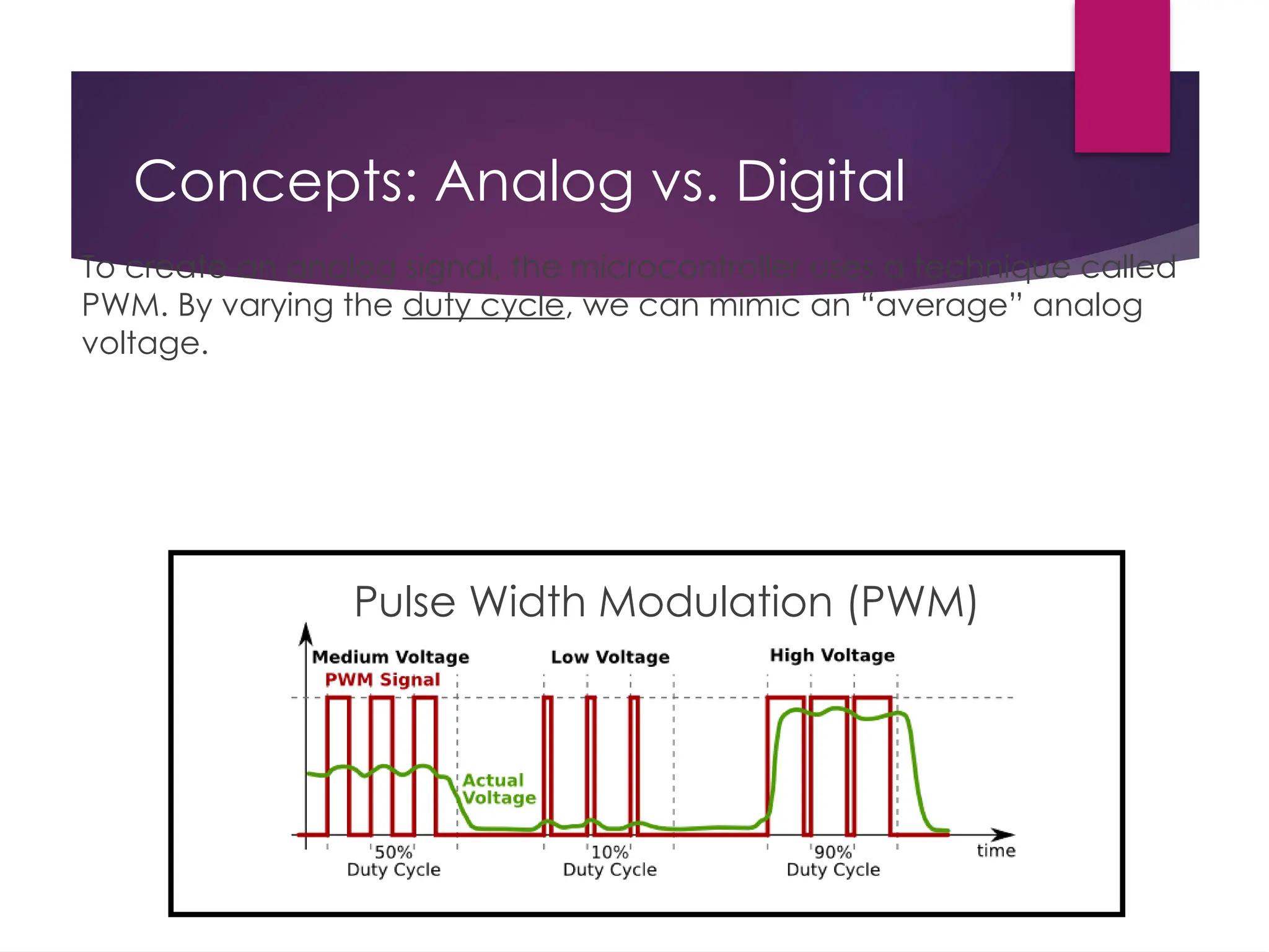
Concepts: Analog vs.Digital Pulse Width Modulation (PWM) To create an analog signal, the microcontroller uses a technique called PWM. By varying the duty cycle, we can mimic an “average” analog voltage.
56.
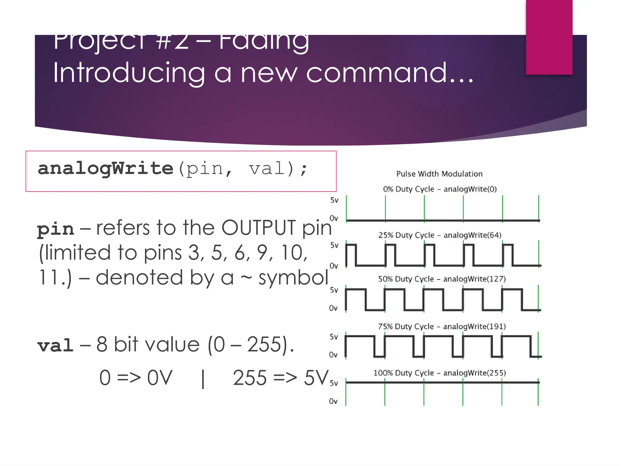
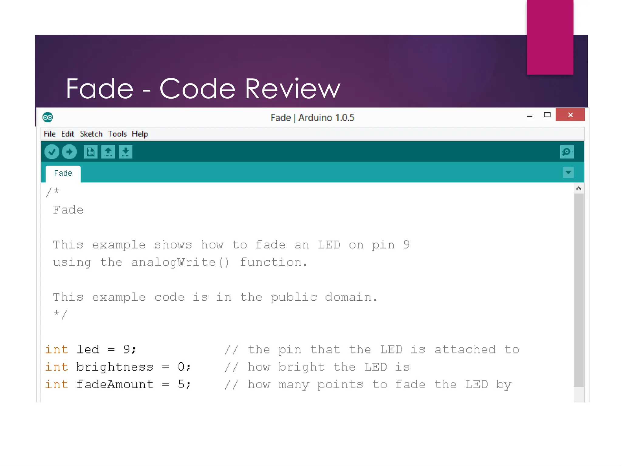
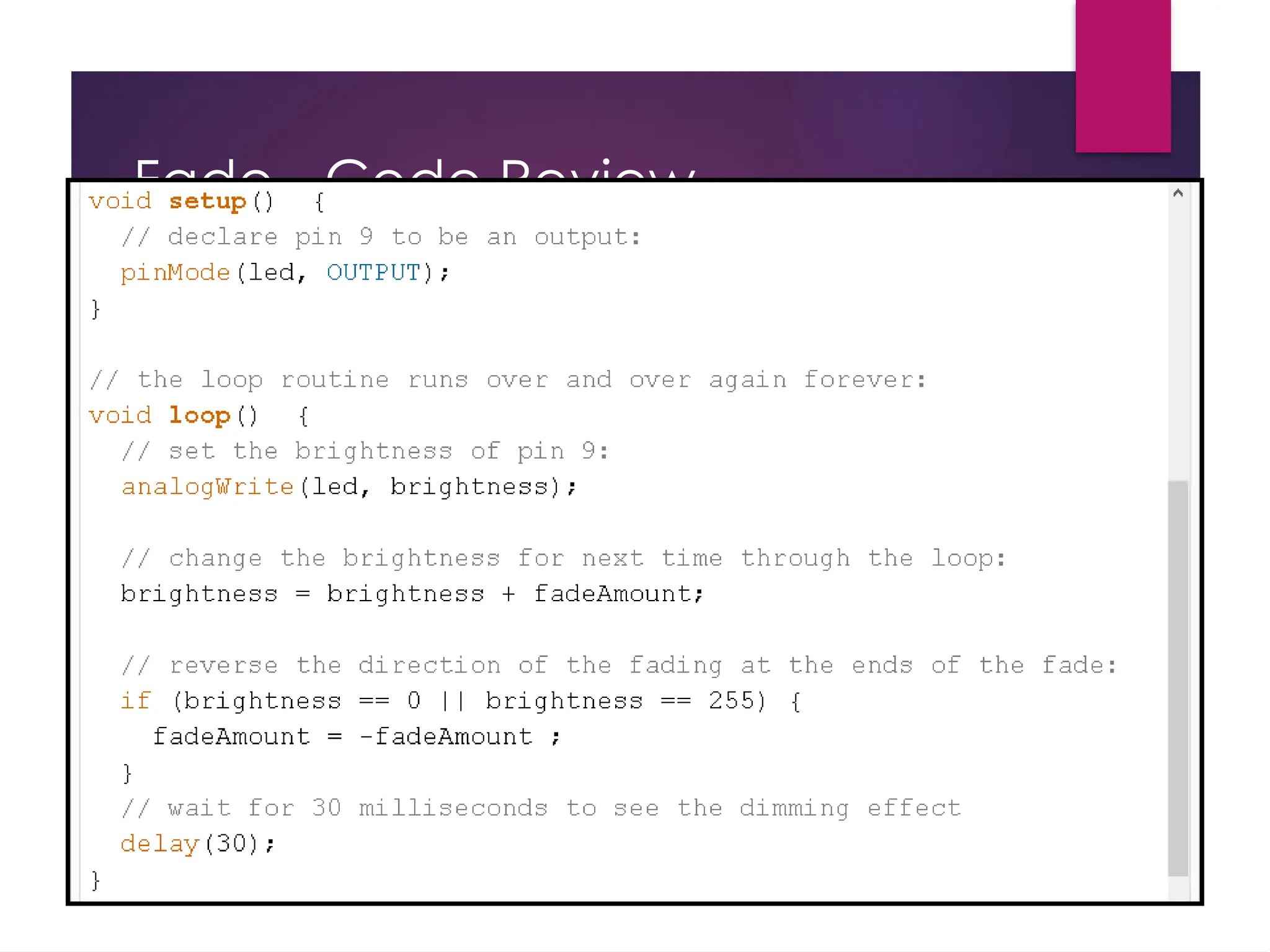
Project #2 –Fading Introducing a new command… analogWrite(pin, val); pin – refers to the OUTPUT pin (limited to pins 3, 5, 6, 9, 10, 11.) – denoted by a ~ symbol val – 8 bit value (0 – 255). 0 => 0V | 255 => 5V
57.
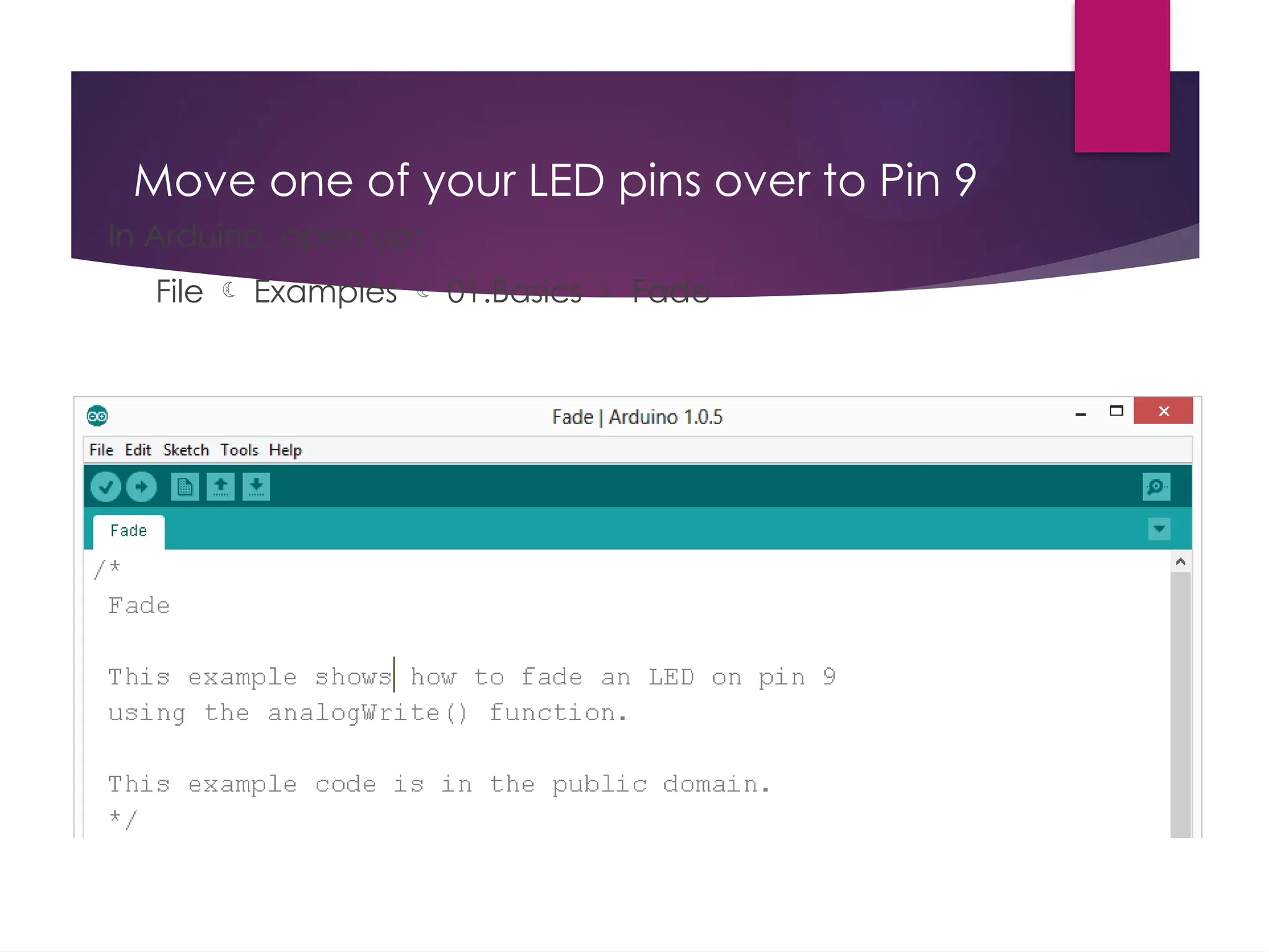
Move one ofyour LED pins over to Pin 9 In Arduino, open up: File Examples 01.Basics Fade
#7 Processor There are two classifications of computers: complex instruction set computer (CISC) and reduced instruction set computer (RISC). In reality, there is a spectrum of architectures that we can classify as CISC or RISC. We make these general observations when deciding whether to call a computer CISC or RISC: Complex instruction set computers (CISC) Early computers offered CPUs that were much faster than available memories. Fetching instructions limited performance A single complex instruction could perform many operations Example: Find the zeros of a polynomial Complex instructions require many processor clock cycles to complete and most instructions can access memory A program running on a CISC computer employed a relatively small number of complex instructions High code density, many instruction types w/ varying length, fewer and specialized registers, many addressing modes Complexity is embedded in the processor hardware (overhead) Examples: Intel (x86), Freescale 9S12 Reduced Instruction Set Computers (RISC) Memories match CPU speed No large penalty for instruction fetch Instructions simplified Example: dedicated load/store instructions, regular instructions can not access memory but only registers Single processor clock cycle per instruction (pipelined) A program running on a RISC computer employs a relatively larger number of simplified instructions Reduced code density, few instructions w/ fixed delay (pipeline!), many identical general-purpose registers, few addressing modes Complexity exists in the assembly code generated by the programmer or compiler, hardware is simple (low overhead/low power) Examples: LC3, MIPS, ARM, SPARC, PowerPC Which architecture is best is beyond the scope of this class, but it is important to recognize the terminology. It is very difficult to compare the execution speed of two computers, especially between a CISC and a RISC. One way to compare is to run a benchmark program on both, and measure the time it takes to execute. Time to execute benchmark = Instructions/program * Average cycles/instruction * Seconds/cycle For example, the 50 MHz ARM Cortex M has one bus cycle every 20ns. One average it may require 1.5 cycles per instruction. If the benchmark program executes 10,000,000 assembly instructions, then the time to execute the benchmark will be 0.3 seconds. Memory: EPROMs are Erasable Programmable ROMs. The mechanism used to erase and write is UV light EEPROMs are Electrically Erasable Flash memory is like EEPROM however writes are performed in large blocks as opposed to single bytes. Cheaper hence popular DRAMs require a periodic refresh SRAMs don’t. Both are volatile therefore are lost when powered down. Interfaces: Parallel - binary data is available simultaneously on groups of lines Serial - binary data is available one bit at a time on a single line Analog - data is encoded as a variable voltage Time - data is encoded as a period, frequency, pulse width or phase shift I/O Memory-mapped I/O I/O ports/registers appear as addresses on common bus with memory I/O ports/registers are accessed as though they are locations in memory Employed on the ARM, Freescale and TI processors I/O-mapped I/O I/O ports/registers have separate control signals from those used with memory Special instructions are used to access I/O ports/registers Employed on Intel x86 processors
#8 Requirements are broad and Specifications go into the details.
#36 Be sure to point out the what all of the buttons do.
#37 All connections to computers- mice, printers etc use a serial port. Gotta pick the right one.
#38 All connections to computers- mice, printers etc use a serial port. Gotta pick the right one.