The document covers an Arduino workshop, explaining Arduino as an open-source electronics prototyping platform meant for artists and designers. It details Arduino's significance, capabilities, and various components, as well as basic electrical concepts related to Arduino use. Additionally, it provides insights into programming with Arduino, including sketches, loops, and the use of components such as sensors and actuators.


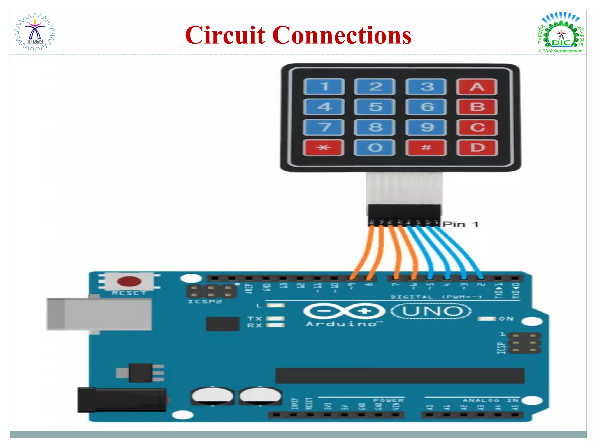
![Code & Explanation /* Program for Using Keypad with Arduino */ #include <Keypad.h> #include <Wire.h> const byte Rows= 4; //number of rows on the keypad i.e. 4 const byte Cols= 4; char keymap[Rows][Cols]= { {'1', '2', '3','A'}, {'4', '5', '6','B'}, {'7', '8', '9','C'}, {'*', '0', '#','D'} }; //a char array is defined byte rPins[Rows]= {9,8,7,6}; //Rows 0 to 3 byte cPins[Cols]= {5,4,3,2}; //Columns 0 to 3 // command for library for keypad Keypad kpd= Keypad(makeKeymap(keymap), rPins, cPins, Rows, Cols); void setup(){ Serial.begin(9600); // serial monitor } //If key is pressed, this key is stored in 'keypressed' variable’ //If key is not equal to 'NO_KEY', then this key is printed out void loop() //main program { char keypressed = kpd.getKey(); if (keypressed != NO_KEY) { Serial.print(keypressed); // write this string on the top row } }](https://image.slidesharecdn.com/arduinoworkshopday1-basicarduino-191210044704/75/Arduino-Workshop-Day-1-Basic-Arduino-60-2048.jpg)