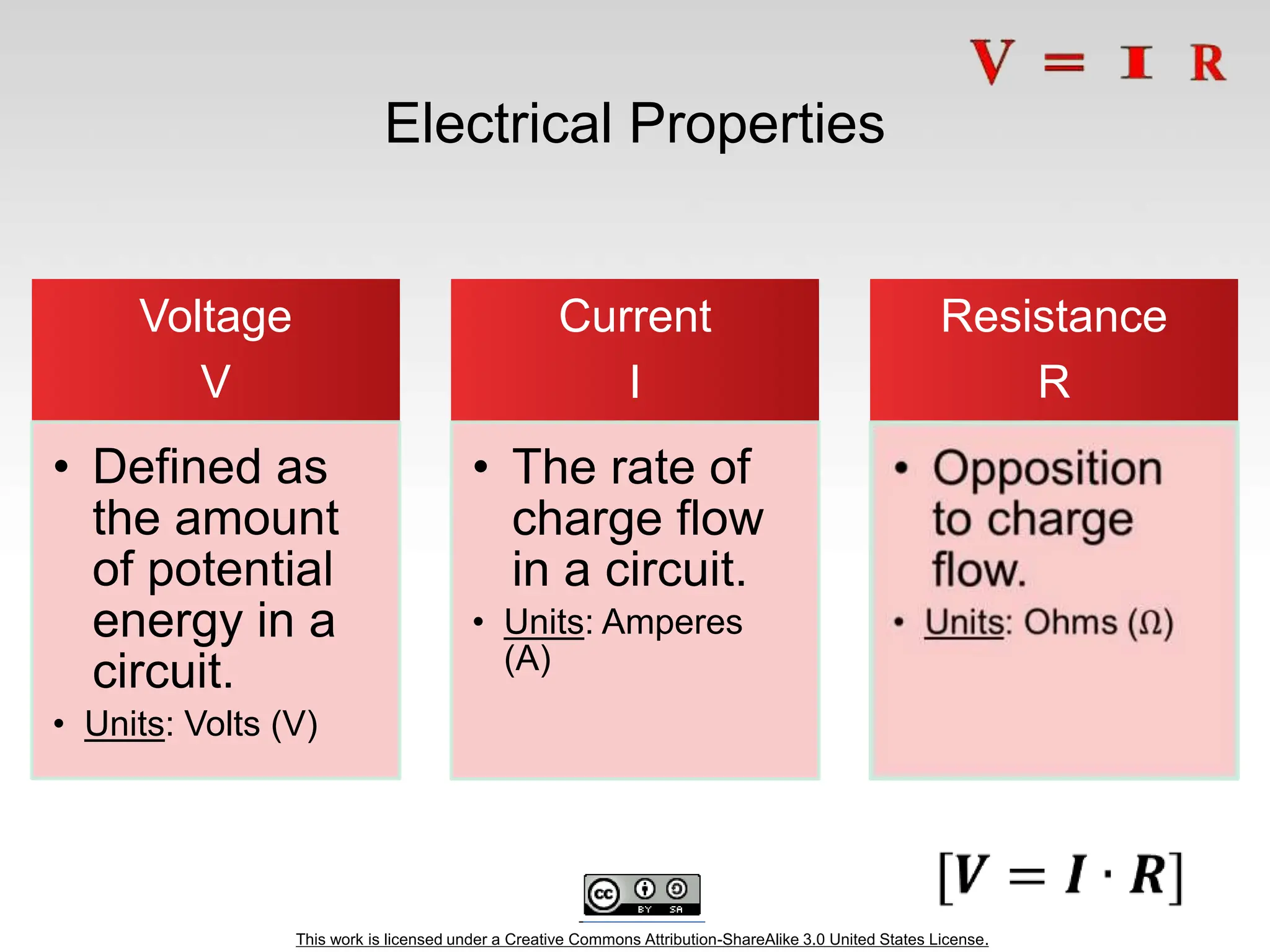
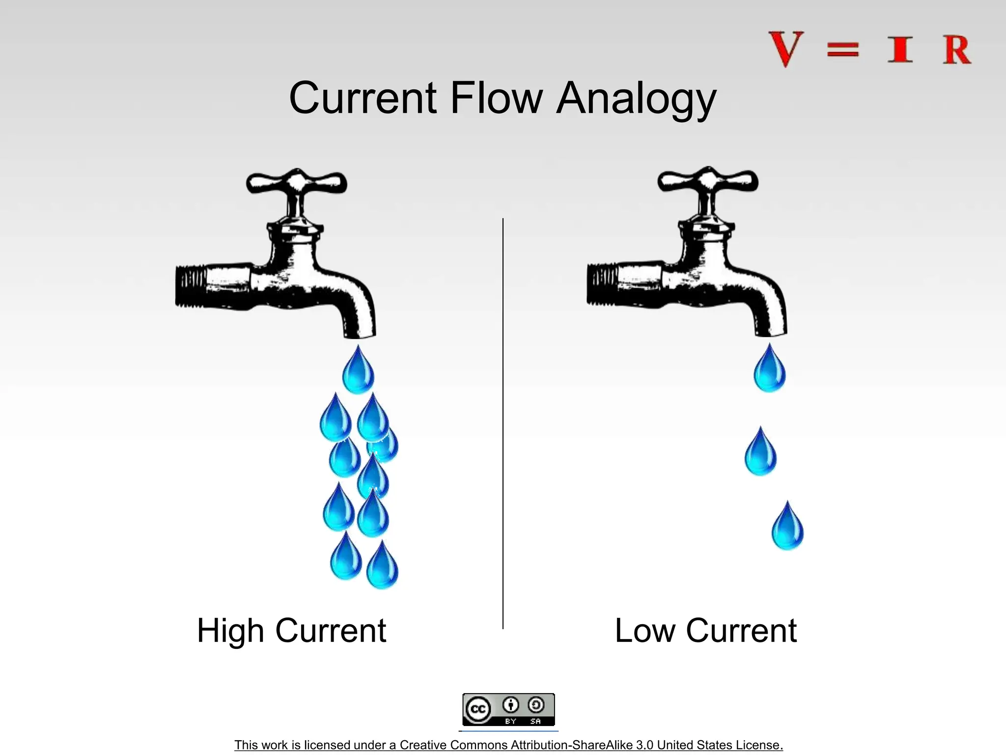
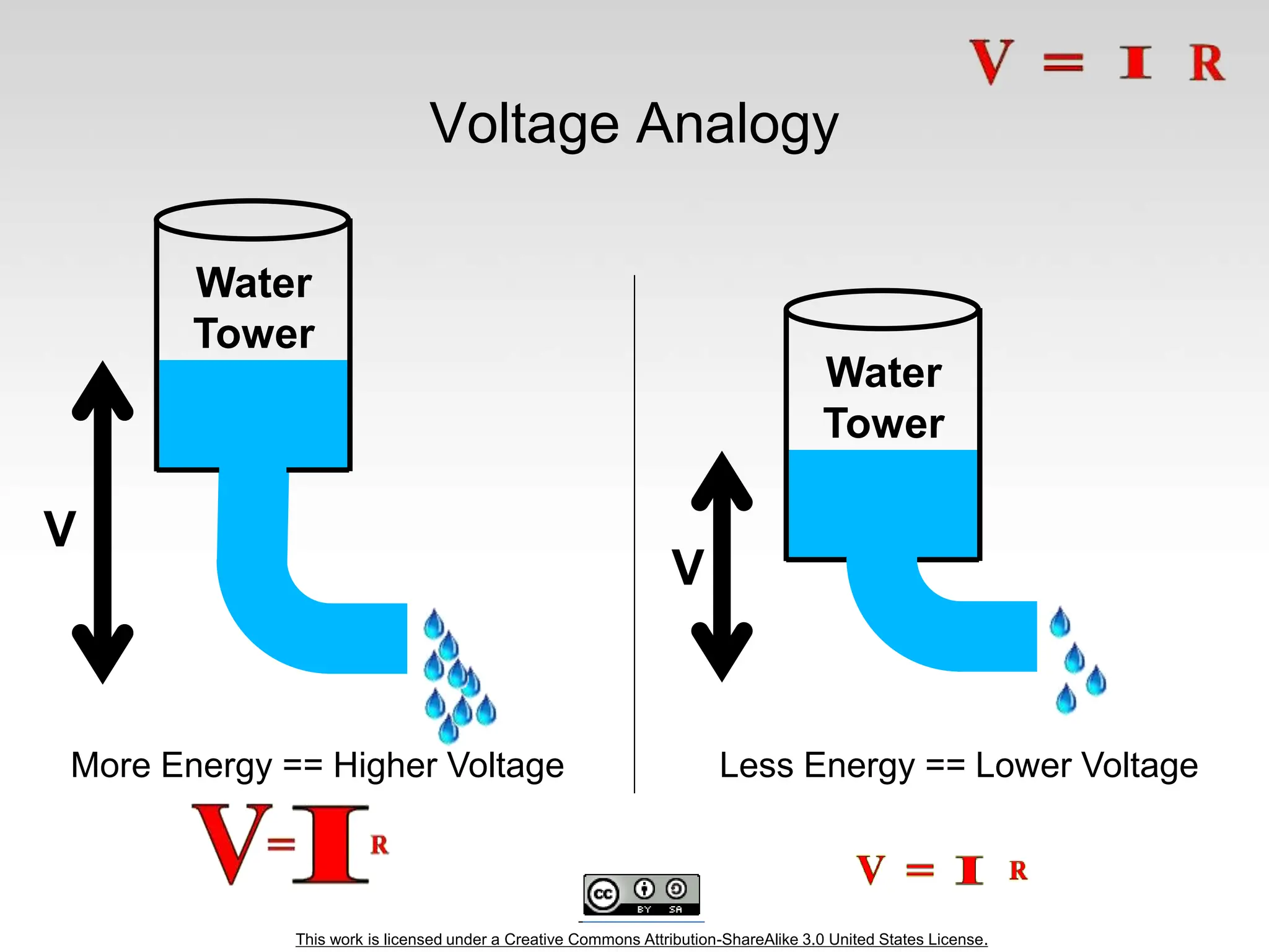
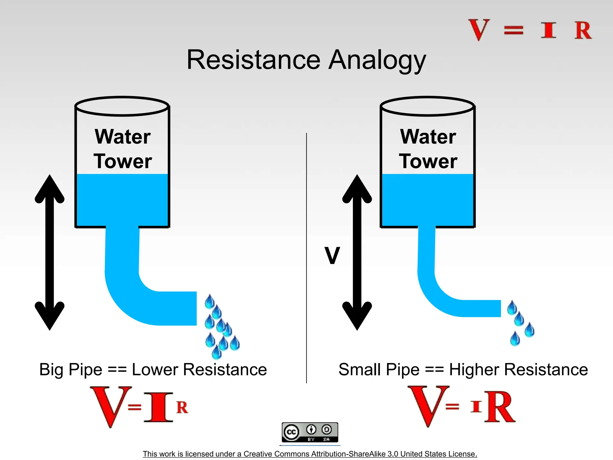
This work is licensed under a Creative Commons Attribution-ShareAlike 3.0 United States License. Overview of Class Getting Started: Installation, Applications and Materials Electrical: Components, Ohm's Law, Input and Output, Analog and Digital ----------------------------- Programming: Split into groups depending on experience Serial Communication Basics: Troubleshooting and Debugging Virtual Prototyping: Schematics and PCB Layout in Fritzing
This work is licensed under a Creative Commons Attribution-ShareAlike 3.0 United States License. Arduino Board “Strong Friend” Created in Ivrea, Italy in 2005 by Massimo Banzi & David Cuartielles Open Source Hardware Processor Coding is accessible & transferrable  (C++, Processing, java)
This work is licensed under a Creative Commons Attribution-ShareAlike 3.0 United States License. Arduino… is the go-to gear for artists, hobbyists, students, and anyone with a gadgetry dream. rose out of another formidable challenge: how to teach students to create electronics, fast. http://spectrum.ieee.org/geek-life/hands-on/the-making-of-arduino
This work is licensed under a Creative Commons Attribution-ShareAlike 3.0 United States License. Getting Started • SW Installation: Arduino (v.1.0+) Fritzing SIK Guide Code Drivers (FTDI) • Materials: SIK Guide Analog I/O, Digital I/O, Serial, & Fritzing handouts Arduino CheatSheet
This work is licensed under a Creative Commons Attribution-ShareAlike 3.0 United States License. Analog INPUTS Digital IO PWM(3, 5, 6, 9, 10, 11) PWR IN USB (to Computer) SCLSDA (I2C Bus) POWER 5V / 3.3V / GND RESET
This work is licensed under a Creative Commons Attribution-ShareAlike 3.0 United States License. Go ahead and plug your board in!
This work is licensed under a Creative Commons Attribution-ShareAlike 3.0 United States License. Arduino Shields PCB Built Shield Inserted Shield
This work is licensed under a Creative Commons Attribution-ShareAlike 3.0 United States License. Arduino Shields Micro SD MP3 Trigger LCD
This work is licensed under a Creative Commons Attribution-ShareAlike 3.0 United States License. SIK Components Push Button Digital Input Switch - Closes or opens circuit Polarized, needs resistor Trim potentiometer Analog Input Variable resistor Also called a Trimpot. Photoresistor Analog Input Light Dependent Resistor (LDR) Resistance varies with light. Relay Digital Output Switch driven by a small signal Used to control larger voltages Temp Sensor Analog Input Temp Dependent Resistor Flex Sensor Analog Input Variable resistor Soft Trimpot Analog Input Variable resistor Careful of shorts RGB LED Dig & Analog Output 16,777,216 different colors Ooh... So pretty. Name Image Type Function Notes
This work is licensed under a Creative Commons Attribution-ShareAlike 3.0 United States License. SIK Components
This work is licensed under a Creative Commons Attribution-ShareAlike 3.0 United States License.
This work is licensed under a Creative Commons Attribution-ShareAlike 3.0 United States License. Electricity Electronics Basic Concept Review • Ohms Law • Voltage • Current • Resistance • Using a Multi-meter
This work is licensed under a Creative Commons Attribution-ShareAlike 3.0 United States License. Ohm’s Law
This work is licensed under a Creative Commons Attribution-ShareAlike 3.0 United States License. Electrical Properties Voltage V • Defined as the amount of potential energy in a circuit. • Units: Volts (V) Current I • The rate of charge flow in a circuit. • Units: Amperes (A) Resistance R
This work is licensed under a Creative Commons Attribution-ShareAlike 3.0 United States License. Current Flow Analogy High Current Low Current
This work is licensed under a Creative Commons Attribution-ShareAlike 3.0 United States License. Water Tower Voltage Analogy More Energy == Higher Voltage Less Energy == Lower Voltage V Water Tower V
This work is licensed under a Creative Commons Attribution-ShareAlike 3.0 United States License. Resistance Analogy Big Pipe == Lower Resistance Small Pipe == Higher Resistance Water Tower Water Tower V
This work is licensed under a Creative Commons Attribution-ShareAlike 3.0 United States License. Continuity – Is it a Circuit? The word “circuit” is derived from the circle. An Electrical Circuit must have a continuous LOOP from Power (Vcc) to Ground (GND). Continuity is important to make portions of circuits are connect. Continuity is the simplest and possibly the most important setting on your multi-meter. Sometimes we call this “ringing out” a circuit.
This work is licensed under a Creative Commons Attribution-ShareAlike 3.0 United States License. Measuring Electricity – Voltage Voltage is a measure of potential electrical energy. A voltage is also called a potential difference – it is measured between two points in a circuit – across a device.
This work is licensed under a Creative Commons Attribution-ShareAlike 3.0 United States License. Measuring Electricity -- Current Current is the measure of the rate of charge flow. For Electrical Engineers – we consider this to be the movement of electrons. In order to measure this – you must break the circuit or insert the meter in-line (series).
This work is licensed under a Creative Commons Attribution-ShareAlike 3.0 United States License. Measuring Electricity -- Resistance Resistance is the measure of how much opposition to current flow is in a circuit. Components should be removed entirely from the circuit to measure resistance. Note the settings on the multi- meter. Make sure that you are set for the appropriate range. Resistance settings
This work is licensed under a Creative Commons Attribution-ShareAlike 3.0 United States License. Prototyping Circuits Solderless Breadboard One of the most useful tools in an engineer or Maker’s toolkit. The three most important things: • A breadboard is easier than soldering • A lot of those little holes are connected, which ones? • Sometimes breadboards break
This work is licensed under a Creative Commons Attribution-ShareAlike 3.0 United States License. What’s a Breadboard?
This work is licensed under a Creative Commons Attribution-ShareAlike 3.0 United States License. Solderless Breadboard Each row (horiz.) of 5 holes are connected. Vertical columns – called power bus are connected vertically
This work is licensed under a Creative Commons Attribution-ShareAlike 3.0 United States License. Using the Breadboard to built a simple circuit Use the breadboard to wire up a single LED with a 330 Ohm Resistor (Orange- Orange-Brown). Note: the longer leg on the LED is the positive leg and the shorter leg is the negative
This work is licensed under a Creative Commons Attribution-ShareAlike 3.0 United States License. Fritzing View of Breadboard Circuit What happens when you break the circuit? What if you wanted to add more than one LED?
This work is licensed under a Creative Commons Attribution-ShareAlike 3.0 United States License. Adding control – let’s use the Arduino and start programming!!!
This work is licensed under a Creative Commons Attribution-ShareAlike 3.0 United States License. Concepts: INPUT vs. OUTPUT Referenced from the perspective of the microcontroller (electrical board). Inputs is a signal / information going into the board. Output is any signal exiting the board. Almost all systems that use physical computing will have some form of output What are some examples of Outputs?
This work is licensed under a Creative Commons Attribution-ShareAlike 3.0 United States License. Concepts: INPUT vs. OUTPUT Referenced from the perspective of the microcontroller (electrical board). Inputs is a signal / information going into the board. Output is any signal exiting the board. Examples: Buttons Switches, Light Sensors, Flex Sensors, Humidity Sensors, Temperature Sensors… Examples: LEDs, DC motor, servo motor, a piezo buzzer, relay, an RGB LED
This work is licensed under a Creative Commons Attribution-ShareAlike 3.0 United States License. Concepts: Analog vs. Digital Microcontrollers are digital devices – ON or OFF. Also called – discrete. analog signals are anything that can be a full range of values. What are some examples? More on this later… 5 V 0 V 5 V 0 V
This work is licensed under a Creative Commons Attribution-ShareAlike 3.0 United States License. Open up Arduino Hints: For PC Users  1.Let the installer copy and move the files to the appropriate locations, or 2.Create a folder under C:Program Files (x86) called Arduino. Move the entire Arduino program folder here. For Mac Users  1. Move the Arduino executable to the dock for ease of access. 2. Resist the temptation to run these from your desktop.
Arduino Integrated Development Environment (IDE) Two required functions / methods / routines: void setup() { // runs once } void loop() { // repeats } error & status messages
This work is licensed under a Creative Commons Attribution-ShareAlike 3.0 United States License. Settings: Tools  Serial Port Your computer communicates to the Arduino microcontroller via a serial port  through a USB-Serial adapter. Check to make sure that the drivers are properly installed.
This work is licensed under a Creative Commons Attribution-ShareAlike 3.0 United States License. Settings: Tools  Board Next, double-check that the proper board is selected under the ToolsBoard menu.
This work is licensed under a Creative Commons Attribution-ShareAlike 3.0 United States License. Arduino & Arduino Compatible Boards
This work is licensed under a Creative Commons Attribution-ShareAlike 3.0 United States License. digitalWrite() analogWrite() digitalRead() if() statements / Boolean analogRead() Serial communication This work is licensed under a Creative Commons Attribution-ShareAlike 3.0 United States License. BIG 6 CONCEPTS
This work is licensed under a Creative Commons Attribution-ShareAlike 3.0 United States License. Let’s get to coding… Project #1 – Blink “Hello World” of Physical Computing Psuedo-code – how should this work? Turn LED ON Wait Turn LED OFF Wait Rinse & Repeat
This work is licensed under a Creative Commons Attribution-ShareAlike 3.0 United States License. Comments, Comments, Comments Comments are for you – the programmer and your friends…or anyone else human that might read your code. // this is for single line comments // it’s good to put a description at the top and before anything ‘tricky’ /* this is for multi-line comments Like this… And this…. */
This work is licensed under a Creative Commons Attribution-ShareAlike 3.0 United States License. comments
This work is licensed under a Creative Commons Attribution-ShareAlike 3.0 United States License. Three commands to know… pinMode(pin, INPUT/OUTPUT); ex: pinMode(13, OUTPUT); digitalWrite(pin, HIGH/LOW); ex: digitalWrite(13, HIGH); delay(time_ms); ex: delay(2500); // delay of 2.5 sec. // NOTE: -> commands are CASE-sensitive
This work is licensed under a Creative Commons Attribution-ShareAlike 3.0 United States License. Project #1: Wiring Diagram Move the green wire from the power bus to pin 13 (or any other Digital I/O pin on the Arduino board. Image created in Fritzing
This work is licensed under a Creative Commons Attribution-ShareAlike 3.0 United States License. A few simple challenges Let’s make LED#13 blink! Challenge 1a – blink with a 200 ms second interval. Challenge 1b – blink to mimic a heartbeat Challenge 1c – find the fastest blink that the human eye can still detect… 1 ms delay? 2 ms delay? 3 ms delay???
This work is licensed under a Creative Commons Attribution-ShareAlike 3.0 United States License. Try adding other LEDs
This work is licensed under a Creative Commons Attribution-ShareAlike 3.0 United States License. Programming Concepts: Variables Variable Scope Global --- Function-level
This work is licensed under a Creative Commons Attribution-ShareAlike 3.0 United States License. Programming Concepts: Variable Types Variable Types: 8 bits 16 bits 32 bits byte char int unsigned int long unsigned long float
This work is licensed under a Creative Commons Attribution-ShareAlike 3.0 United States License. Fading in and Fading Out (Analog or Digital?) A few pins on the Arduino allow for us to modify the output to mimic an analog signal. This is done by a technique called: Pulse Width Modulation (PWM)
This work is licensed under a Creative Commons Attribution-ShareAlike 3.0 United States License. Concepts: Analog vs. Digital To create an analog signal, the microcontroller uses a technique called PWM. By varying the duty cycle, we can mimic an “average” analog voltage. Pulse Width Modulation (PWM)
This work is licensed under a Creative Commons Attribution-ShareAlike 3.0 United States License. analogWrite(pin, val); pin – refers to the OUTPUT pin (limited to pins 3, 5, 6, 9, 10, 11.) – denoted by a ~ symbol val – 8 bit value (0 – 255). 0 => 0V | 255 => 5V Project #2 – Fading Introducing a new command…
This work is licensed under a Creative Commons Attribution-ShareAlike 3.0 United States License. Move one of your LED pins over to Pin 9 In Arduino, open up: File  Examples  01.Basics  Fade
This work is licensed under a Creative Commons Attribution-ShareAlike 3.0 United States License. Fade - Code Review
This work is licensed under a Creative Commons Attribution-ShareAlike 3.0 United States License. Project# 2 -- Fading Challenge 2a – Change the rate of the fading in and out. There are at least two different ways to do this – can you figure them out? Challenge 2b – Use 2 (or more) LEDs – so that one fades in as the other one fades out.
This work is licensed under a Creative Commons Attribution-ShareAlike 3.0 United States License. Color Mixing Tri-color LED In the SIK, this is a standard – Common Cathode LED This means the negative side of the LED is all tied to Ground. R G B
This work is licensed under a Creative Commons Attribution-ShareAlike 3.0 United States License. Project 3 – RGB LED Note: The longest leg of the RGB LED is the Common Cathode. This goes to GND. Use pins 5, 6, & 9
This work is licensed under a Creative Commons Attribution-ShareAlike 3.0 United States License. How many unique colors can you create? Use Colorpicker.com or experiment on your own. Pick out a few colors that you want to try re- creating for a lamp or lighting display... Play around with this with the analogWrite() command.
This work is licensed under a Creative Commons Attribution-ShareAlike 3.0 United States License. RGB LED Color Mixing int redPin = 5; int greenPin = 6; int bluePin = 9; void setup() { pinMode(redPin, OUTPUT); pinMode(greenPin, OUTPUT); pinMode(bluePin, OUTPUT); }
This work is licensed under a Creative Commons Attribution-ShareAlike 3.0 United States License. RGB LED Color Mixing void loop() { analogWrite(redPin, 255); analogWrite (greenPin, 255); analogWrite (bluePin, 255); }
This work is licensed under a Creative Commons Attribution-ShareAlike 3.0 United States License. Project: Mood Lamp / Light Sculpture
This work is licensed under a Creative Commons Attribution-ShareAlike 3.0 United States License. Napkin Schematics Emphasize the engineering design process with students. We like to skirt the line between formal and informal with a tool called Napkin Schematics.
This work is licensed under a Creative Commons Attribution-ShareAlike 3.0 United States License. Driving Motors or other High Current Loads NPN Transistor (Common Emitter “Amplifier” Circuit) to Digital Pin 9
This work is licensed under a Creative Commons Attribution-ShareAlike 3.0 United States License. Input Input is any signal entering an electrical system. • Both digital and analog sensors are forms of input • Input can also take many other forms: Keyboards, a mouse, infrared sensors, biometric sensors, or just plain voltage from a circuit
This work is licensed under a Creative Commons Attribution-ShareAlike 3.0 United States License. Project #4 – Digital Input In Arduino, open up: File  Examples  02.Digital  Button
This work is licensed under a Creative Commons Attribution-ShareAlike 3.0 United States License. Digital Sensors (a.k.a. Switches) Pull-up Resistor (circuit) to Digital Pin 2
This work is licensed under a Creative Commons Attribution-ShareAlike 3.0 United States License. Digital Sensors (a.k.a. Switches) Add an indicator LED to Pin 13 This is just like our 1st circuit!
This work is licensed under a Creative Commons Attribution-ShareAlike 3.0 United States License. Digital Input • Connect digital input to your Arduino using Pins # 0 – 13 (Although pins # 0 & 1 are also used for programming) • Digital Input needs a pinMode command: pinMode (pinNumber, INPUT); Make sure to use ALL CAPS for INPUT • To get a digital reading: int buttonState = digitalRead (pinNumber); • Digital Input values are only HIGH (On) or LOW (Off)
This work is licensed under a Creative Commons Attribution-ShareAlike 3.0 United States License. Digital Sensors • Digital sensors are more straight forward than Analog • No matter what the sensor there are only two settings: On and Off • Signal is always either HIGH (On) or LOW (Off) • Voltage signal for HIGH will be a little less than 5V on your Uno • Voltage signal for LOW will be 0V on most systems
This work is licensed under a Creative Commons Attribution-ShareAlike 3.0 United States License. http://opensourcehardwarejunkies.com/tutorial-03-digitalread-and-
This work is licensed under a Creative Commons Attribution-ShareAlike 3.0 United States License. Programming: Conditional Statements if()
This work is licensed under a Creative Commons Attribution-ShareAlike 3.0 United States License. void loop() { int buttonState = digitalRead(5); if(buttonState == LOW) { // do something } else { // do something else } } Programming: Conditional Statements if() DIG INPUT
This work is licensed under a Creative Commons Attribution-ShareAlike 3.0 United States License. Boolean Operators <Boolean> Description ( ) == ( ) is equal? ( ) != ( ) is not equal? ( ) > ( ) greater than ( ) >= ( ) greater than or equal ( ) < ( ) less than ( ) <= ( ) less than or equal
This work is licensed under a Creative Commons Attribution-ShareAlike 3.0 United States License. Trimpot (Potentiometer) Variable Resistor wiper fixed end fixed end
This work is licensed under a Creative Commons Attribution-ShareAlike 3.0 United States License. Analog Sensors 3 Pin Potentiometer = var. resistor (circuit) a.k.a. Voltage Divider Circuit 1.0 V 1.0 V wiper fixed ends
This work is licensed under a Creative Commons Attribution-ShareAlike 3.0 United States License. Ohms Law… (just the basics) Actually, this is the “voltage divider”
This work is licensed under a Creative Commons Attribution-ShareAlike 3.0 United States License. analogRead() Arduino uses a 10-bit A/D Converter: • this means that you get input values from 0 to 1023 • 0 V  0 • 5 V  1023 Ex: int sensorValue = analogRead(A0);
This work is licensed under a Creative Commons Attribution-ShareAlike 3.0 United States License. Using Serial Communication Method used to transfer data between two devices. Arduino dedicates Digital I/O pin # 0 to receiving and Digital I/O pin #1 to transmit. Data passes between the computer and Arduino through the USB cable. Data is transmitted as zeros (‘0’) and ones (‘1’) sequentially.
This work is licensed under a Creative Commons Attribution-ShareAlike 3.0 United States License. Serial Monitor & analogRead() Initializes the Serial Communication 9600 baud data rate prints data to serial bus
This work is licensed under a Creative Commons Attribution-ShareAlike 3.0 United States License. Serial Monitor & analogRead() Opens up a Serial Terminal Window
This work is licensed under a Creative Commons Attribution-ShareAlike 3.0 United States License. Analog Sensors 2 Pin Analog Sensors = var. resistor Take two sensors -- Use the Serial Monitor and find the range of input values you get for each sensor. MaxAnalogRead = _________ MinAnalogRead = _________
This work is licensed under a Creative Commons Attribution-ShareAlike 3.0 United States License. Analog Sensors Examples: Sensors Variables Mic soundVolume Photoresistor lightLevel Potentiometer dialPosition Temp Sensor temperature Flex Sensor bend Accelerometer tilt/acceleration
This work is licensed under a Creative Commons Attribution-ShareAlike 3.0 United States License. Additional Serial Communication Sending a Message void loop ( ) { Serial.print(“Hands on “) ; Serial.print(“Learning ”) ; Serial.println(“is Fun!!!”) ; }
This work is licensed under a Creative Commons Attribution-ShareAlike 3.0 United States License.
This work is licensed under a Creative Commons Attribution-ShareAlike 3.0 United States License. Serial Communication: Serial Debugging void loop() { int xVar = 10; Serial.print ( “Variable xVar is “ ) ; Serial.println ( xVar ) ; }
This work is licensed under a Creative Commons Attribution-ShareAlike 3.0 United States License. Serial Communication: Serial Troubleshooting void loop ( ) { Serial.print (“Digital pin 9: “); Serial.println (digitalRead(9)); }
This work is licensed under a Creative Commons Attribution-ShareAlike 3.0 United States License. Virtual Electrical Prototyping Project started in 2007 by the Interaction Design Lab at the University of Applied Science Potsdam, Germany Open Source Prototypes: Document, Share, Teach, Manufacture
This work is licensed under a Creative Commons Attribution-ShareAlike 3.0 United States License. Now that you feel comfortable putting together circuits with your breadboard let’s talk about how to go from the breadboard to a PCB
This work is licensed under a Creative Commons Attribution-ShareAlike 3.0 United States License. Free Time The rest of the class is dedicated to free pursuit Experiment with the various circuits and lessons in the SIK. Explore the additional tutorials available on learn.sparkfun.com Thank you for attending our Intro to Arduino class

Intro_to_Arduino_with_coding_explained.ppt

  • 1.
    This work islicensed under a Creative Commons Attribution-ShareAlike 3.0 United States License. Overview of Class Getting Started: Installation, Applications and Materials Electrical: Components, Ohm's Law, Input and Output, Analog and Digital ----------------------------- Programming: Split into groups depending on experience Serial Communication Basics: Troubleshooting and Debugging Virtual Prototyping: Schematics and PCB Layout in Fritzing
  • 2.
    This work islicensed under a Creative Commons Attribution-ShareAlike 3.0 United States License. Arduino Board “Strong Friend” Created in Ivrea, Italy in 2005 by Massimo Banzi & David Cuartielles Open Source Hardware Processor Coding is accessible & transferrable  (C++, Processing, java)
  • 3.
    This work islicensed under a Creative Commons Attribution-ShareAlike 3.0 United States License. Arduino… is the go-to gear for artists, hobbyists, students, and anyone with a gadgetry dream. rose out of another formidable challenge: how to teach students to create electronics, fast. http://spectrum.ieee.org/geek-life/hands-on/the-making-of-arduino
  • 4.
    This work islicensed under a Creative Commons Attribution-ShareAlike 3.0 United States License. Getting Started • SW Installation: Arduino (v.1.0+) Fritzing SIK Guide Code Drivers (FTDI) • Materials: SIK Guide Analog I/O, Digital I/O, Serial, & Fritzing handouts Arduino CheatSheet
  • 5.
    This work islicensed under a Creative Commons Attribution-ShareAlike 3.0 United States License. Analog INPUTS Digital IO PWM(3, 5, 6, 9, 10, 11) PWR IN USB (to Computer) SCLSDA (I2C Bus) POWER 5V / 3.3V / GND RESET
  • 6.
    This work islicensed under a Creative Commons Attribution-ShareAlike 3.0 United States License. Analog INPUTS Digital IO PWM(3, 5, 6, 9, 10, 11) PWR IN USB (to Computer) SCLSDA (I2C Bus) POWER 5V / 3.3V / GND RESET
  • 7.
    This work islicensed under a Creative Commons Attribution-ShareAlike 3.0 United States License. Go ahead and plug your board in!
  • 8.
    This work islicensed under a Creative Commons Attribution-ShareAlike 3.0 United States License. Arduino Shields PCB Built Shield Inserted Shield
  • 9.
    This work islicensed under a Creative Commons Attribution-ShareAlike 3.0 United States License. Arduino Shields Micro SD MP3 Trigger LCD
  • 10.
    This work islicensed under a Creative Commons Attribution-ShareAlike 3.0 United States License. SIK Components Push Button Digital Input Switch - Closes or opens circuit Polarized, needs resistor Trim potentiometer Analog Input Variable resistor Also called a Trimpot. Photoresistor Analog Input Light Dependent Resistor (LDR) Resistance varies with light. Relay Digital Output Switch driven by a small signal Used to control larger voltages Temp Sensor Analog Input Temp Dependent Resistor Flex Sensor Analog Input Variable resistor Soft Trimpot Analog Input Variable resistor Careful of shorts RGB LED Dig & Analog Output 16,777,216 different colors Ooh... So pretty. Name Image Type Function Notes
  • 11.
    This work islicensed under a Creative Commons Attribution-ShareAlike 3.0 United States License. SIK Components
  • 12.
    This work islicensed under a Creative Commons Attribution-ShareAlike 3.0 United States License. SIK Components
  • 13.
    This work islicensed under a Creative Commons Attribution-ShareAlike 3.0 United States License. SIK Components
  • 14.
    This work islicensed under a Creative Commons Attribution-ShareAlike 3.0 United States License.
  • 15.
    This work islicensed under a Creative Commons Attribution-ShareAlike 3.0 United States License. Electricity Electronics Basic Concept Review • Ohms Law • Voltage • Current • Resistance • Using a Multi-meter
  • 16.
    This work islicensed under a Creative Commons Attribution-ShareAlike 3.0 United States License. Ohm’s Law
  • 17.
    This work islicensed under a Creative Commons Attribution-ShareAlike 3.0 United States License. Electrical Properties Voltage V • Defined as the amount of potential energy in a circuit. • Units: Volts (V) Current I • The rate of charge flow in a circuit. • Units: Amperes (A) Resistance R
  • 18.
    This work islicensed under a Creative Commons Attribution-ShareAlike 3.0 United States License. Current Flow Analogy High Current Low Current
  • 19.
    This work islicensed under a Creative Commons Attribution-ShareAlike 3.0 United States License. Water Tower Voltage Analogy More Energy == Higher Voltage Less Energy == Lower Voltage V Water Tower V
  • 20.
    This work islicensed under a Creative Commons Attribution-ShareAlike 3.0 United States License. Resistance Analogy Big Pipe == Lower Resistance Small Pipe == Higher Resistance Water Tower Water Tower V
  • 21.
    This work islicensed under a Creative Commons Attribution-ShareAlike 3.0 United States License. Continuity – Is it a Circuit? The word “circuit” is derived from the circle. An Electrical Circuit must have a continuous LOOP from Power (Vcc) to Ground (GND). Continuity is important to make portions of circuits are connect. Continuity is the simplest and possibly the most important setting on your multi-meter. Sometimes we call this “ringing out” a circuit.
  • 22.
    This work islicensed under a Creative Commons Attribution-ShareAlike 3.0 United States License. Measuring Electricity – Voltage Voltage is a measure of potential electrical energy. A voltage is also called a potential difference – it is measured between two points in a circuit – across a device.
  • 23.
    This work islicensed under a Creative Commons Attribution-ShareAlike 3.0 United States License. Measuring Electricity -- Current Current is the measure of the rate of charge flow. For Electrical Engineers – we consider this to be the movement of electrons. In order to measure this – you must break the circuit or insert the meter in-line (series).
  • 24.
    This work islicensed under a Creative Commons Attribution-ShareAlike 3.0 United States License. Measuring Electricity -- Resistance Resistance is the measure of how much opposition to current flow is in a circuit. Components should be removed entirely from the circuit to measure resistance. Note the settings on the multi- meter. Make sure that you are set for the appropriate range. Resistance settings
  • 25.
    This work islicensed under a Creative Commons Attribution-ShareAlike 3.0 United States License. Prototyping Circuits Solderless Breadboard One of the most useful tools in an engineer or Maker’s toolkit. The three most important things: • A breadboard is easier than soldering • A lot of those little holes are connected, which ones? • Sometimes breadboards break
  • 26.
    This work islicensed under a Creative Commons Attribution-ShareAlike 3.0 United States License. What’s a Breadboard?
  • 27.
    This work islicensed under a Creative Commons Attribution-ShareAlike 3.0 United States License. Solderless Breadboard Each row (horiz.) of 5 holes are connected. Vertical columns – called power bus are connected vertically
  • 28.
    This work islicensed under a Creative Commons Attribution-ShareAlike 3.0 United States License. Using the Breadboard to built a simple circuit Use the breadboard to wire up a single LED with a 330 Ohm Resistor (Orange- Orange-Brown). Note: the longer leg on the LED is the positive leg and the shorter leg is the negative
  • 29.
    This work islicensed under a Creative Commons Attribution-ShareAlike 3.0 United States License. Fritzing View of Breadboard Circuit What happens when you break the circuit? What if you wanted to add more than one LED?
  • 30.
    This work islicensed under a Creative Commons Attribution-ShareAlike 3.0 United States License. Adding control – let’s use the Arduino and start programming!!!
  • 31.
    This work islicensed under a Creative Commons Attribution-ShareAlike 3.0 United States License. Concepts: INPUT vs. OUTPUT Referenced from the perspective of the microcontroller (electrical board). Inputs is a signal / information going into the board. Output is any signal exiting the board. Almost all systems that use physical computing will have some form of output What are some examples of Outputs?
  • 32.
    This work islicensed under a Creative Commons Attribution-ShareAlike 3.0 United States License. Concepts: INPUT vs. OUTPUT Referenced from the perspective of the microcontroller (electrical board). Inputs is a signal / information going into the board. Output is any signal exiting the board. Examples: Buttons Switches, Light Sensors, Flex Sensors, Humidity Sensors, Temperature Sensors… Examples: LEDs, DC motor, servo motor, a piezo buzzer, relay, an RGB LED
  • 33.
    This work islicensed under a Creative Commons Attribution-ShareAlike 3.0 United States License. Concepts: Analog vs. Digital Microcontrollers are digital devices – ON or OFF. Also called – discrete. analog signals are anything that can be a full range of values. What are some examples? More on this later… 5 V 0 V 5 V 0 V
  • 34.
    This work islicensed under a Creative Commons Attribution-ShareAlike 3.0 United States License. Open up Arduino Hints: For PC Users  1.Let the installer copy and move the files to the appropriate locations, or 2.Create a folder under C:Program Files (x86) called Arduino. Move the entire Arduino program folder here. For Mac Users  1. Move the Arduino executable to the dock for ease of access. 2. Resist the temptation to run these from your desktop.
  • 35.
    Arduino Integrated Development Environment(IDE) Two required functions / methods / routines: void setup() { // runs once } void loop() { // repeats } error & status messages
  • 36.
    This work islicensed under a Creative Commons Attribution-ShareAlike 3.0 United States License. Settings: Tools  Serial Port Your computer communicates to the Arduino microcontroller via a serial port  through a USB-Serial adapter. Check to make sure that the drivers are properly installed.
  • 37.
    This work islicensed under a Creative Commons Attribution-ShareAlike 3.0 United States License. Settings: Tools  Board Next, double-check that the proper board is selected under the ToolsBoard menu.
  • 38.
    This work islicensed under a Creative Commons Attribution-ShareAlike 3.0 United States License. Arduino & Arduino Compatible Boards
  • 39.
    This work islicensed under a Creative Commons Attribution-ShareAlike 3.0 United States License. digitalWrite() analogWrite() digitalRead() if() statements / Boolean analogRead() Serial communication This work is licensed under a Creative Commons Attribution-ShareAlike 3.0 United States License. BIG 6 CONCEPTS
  • 40.
    This work islicensed under a Creative Commons Attribution-ShareAlike 3.0 United States License. Let’s get to coding… Project #1 – Blink “Hello World” of Physical Computing Psuedo-code – how should this work? Turn LED ON Wait Turn LED OFF Wait Rinse & Repeat
  • 41.
    This work islicensed under a Creative Commons Attribution-ShareAlike 3.0 United States License. Comments, Comments, Comments Comments are for you – the programmer and your friends…or anyone else human that might read your code. // this is for single line comments // it’s good to put a description at the top and before anything ‘tricky’ /* this is for multi-line comments Like this… And this…. */
  • 42.
    This work islicensed under a Creative Commons Attribution-ShareAlike 3.0 United States License. comments
  • 43.
    This work islicensed under a Creative Commons Attribution-ShareAlike 3.0 United States License. Three commands to know… pinMode(pin, INPUT/OUTPUT); ex: pinMode(13, OUTPUT); digitalWrite(pin, HIGH/LOW); ex: digitalWrite(13, HIGH); delay(time_ms); ex: delay(2500); // delay of 2.5 sec. // NOTE: -> commands are CASE-sensitive
  • 44.
    This work islicensed under a Creative Commons Attribution-ShareAlike 3.0 United States License. Project #1: Wiring Diagram Move the green wire from the power bus to pin 13 (or any other Digital I/O pin on the Arduino board. Image created in Fritzing
  • 45.
    This work islicensed under a Creative Commons Attribution-ShareAlike 3.0 United States License. A few simple challenges Let’s make LED#13 blink! Challenge 1a – blink with a 200 ms second interval. Challenge 1b – blink to mimic a heartbeat Challenge 1c – find the fastest blink that the human eye can still detect… 1 ms delay? 2 ms delay? 3 ms delay???
  • 46.
    This work islicensed under a Creative Commons Attribution-ShareAlike 3.0 United States License. Try adding other LEDs
  • 47.
    This work islicensed under a Creative Commons Attribution-ShareAlike 3.0 United States License. Programming Concepts: Variables Variable Scope Global --- Function-level
  • 48.
    This work islicensed under a Creative Commons Attribution-ShareAlike 3.0 United States License. Programming Concepts: Variable Types Variable Types: 8 bits 16 bits 32 bits byte char int unsigned int long unsigned long float
  • 49.
    This work islicensed under a Creative Commons Attribution-ShareAlike 3.0 United States License. Fading in and Fading Out (Analog or Digital?) A few pins on the Arduino allow for us to modify the output to mimic an analog signal. This is done by a technique called: Pulse Width Modulation (PWM)
  • 50.
    This work islicensed under a Creative Commons Attribution-ShareAlike 3.0 United States License. Concepts: Analog vs. Digital To create an analog signal, the microcontroller uses a technique called PWM. By varying the duty cycle, we can mimic an “average” analog voltage. Pulse Width Modulation (PWM)
  • 51.
    This work islicensed under a Creative Commons Attribution-ShareAlike 3.0 United States License. analogWrite(pin, val); pin – refers to the OUTPUT pin (limited to pins 3, 5, 6, 9, 10, 11.) – denoted by a ~ symbol val – 8 bit value (0 – 255). 0 => 0V | 255 => 5V Project #2 – Fading Introducing a new command…
  • 52.
    This work islicensed under a Creative Commons Attribution-ShareAlike 3.0 United States License. Move one of your LED pins over to Pin 9 In Arduino, open up: File  Examples  01.Basics  Fade
  • 53.
    This work islicensed under a Creative Commons Attribution-ShareAlike 3.0 United States License. Fade - Code Review
  • 54.
    This work islicensed under a Creative Commons Attribution-ShareAlike 3.0 United States License. Fade - Code Review
  • 55.
    This work islicensed under a Creative Commons Attribution-ShareAlike 3.0 United States License. Project# 2 -- Fading Challenge 2a – Change the rate of the fading in and out. There are at least two different ways to do this – can you figure them out? Challenge 2b – Use 2 (or more) LEDs – so that one fades in as the other one fades out.
  • 56.
    This work islicensed under a Creative Commons Attribution-ShareAlike 3.0 United States License. Color Mixing Tri-color LED In the SIK, this is a standard – Common Cathode LED This means the negative side of the LED is all tied to Ground. R G B
  • 57.
    This work islicensed under a Creative Commons Attribution-ShareAlike 3.0 United States License. Project 3 – RGB LED Note: The longest leg of the RGB LED is the Common Cathode. This goes to GND. Use pins 5, 6, & 9
  • 58.
    This work islicensed under a Creative Commons Attribution-ShareAlike 3.0 United States License. How many unique colors can you create? Use Colorpicker.com or experiment on your own. Pick out a few colors that you want to try re- creating for a lamp or lighting display... Play around with this with the analogWrite() command.
  • 59.
    This work islicensed under a Creative Commons Attribution-ShareAlike 3.0 United States License. RGB LED Color Mixing int redPin = 5; int greenPin = 6; int bluePin = 9; void setup() { pinMode(redPin, OUTPUT); pinMode(greenPin, OUTPUT); pinMode(bluePin, OUTPUT); }
  • 60.
    This work islicensed under a Creative Commons Attribution-ShareAlike 3.0 United States License. RGB LED Color Mixing void loop() { analogWrite(redPin, 255); analogWrite (greenPin, 255); analogWrite (bluePin, 255); }
  • 61.
    This work islicensed under a Creative Commons Attribution-ShareAlike 3.0 United States License. Project: Mood Lamp / Light Sculpture
  • 62.
    This work islicensed under a Creative Commons Attribution-ShareAlike 3.0 United States License. Napkin Schematics Emphasize the engineering design process with students. We like to skirt the line between formal and informal with a tool called Napkin Schematics.
  • 63.
    This work islicensed under a Creative Commons Attribution-ShareAlike 3.0 United States License. Napkin Schematics Emphasize the engineering design process with students. We like to skirt the line between formal and informal with a tool called Napkin Schematics.
  • 64.
    This work islicensed under a Creative Commons Attribution-ShareAlike 3.0 United States License. Driving Motors or other High Current Loads NPN Transistor (Common Emitter “Amplifier” Circuit) to Digital Pin 9
  • 65.
    This work islicensed under a Creative Commons Attribution-ShareAlike 3.0 United States License. Input Input is any signal entering an electrical system. • Both digital and analog sensors are forms of input • Input can also take many other forms: Keyboards, a mouse, infrared sensors, biometric sensors, or just plain voltage from a circuit
  • 66.
    This work islicensed under a Creative Commons Attribution-ShareAlike 3.0 United States License. Project #4 – Digital Input In Arduino, open up: File  Examples  02.Digital  Button
  • 67.
    This work islicensed under a Creative Commons Attribution-ShareAlike 3.0 United States License. Digital Sensors (a.k.a. Switches) Pull-up Resistor (circuit) to Digital Pin 2
  • 68.
    This work islicensed under a Creative Commons Attribution-ShareAlike 3.0 United States License. Digital Sensors (a.k.a. Switches) Add an indicator LED to Pin 13 This is just like our 1st circuit!
  • 69.
    This work islicensed under a Creative Commons Attribution-ShareAlike 3.0 United States License. Digital Input • Connect digital input to your Arduino using Pins # 0 – 13 (Although pins # 0 & 1 are also used for programming) • Digital Input needs a pinMode command: pinMode (pinNumber, INPUT); Make sure to use ALL CAPS for INPUT • To get a digital reading: int buttonState = digitalRead (pinNumber); • Digital Input values are only HIGH (On) or LOW (Off)
  • 70.
    This work islicensed under a Creative Commons Attribution-ShareAlike 3.0 United States License. Digital Sensors • Digital sensors are more straight forward than Analog • No matter what the sensor there are only two settings: On and Off • Signal is always either HIGH (On) or LOW (Off) • Voltage signal for HIGH will be a little less than 5V on your Uno • Voltage signal for LOW will be 0V on most systems
  • 71.
    This work islicensed under a Creative Commons Attribution-ShareAlike 3.0 United States License. http://opensourcehardwarejunkies.com/tutorial-03-digitalread-and-
  • 72.
    This work islicensed under a Creative Commons Attribution-ShareAlike 3.0 United States License. Programming: Conditional Statements if()
  • 73.
    This work islicensed under a Creative Commons Attribution-ShareAlike 3.0 United States License. void loop() { int buttonState = digitalRead(5); if(buttonState == LOW) { // do something } else { // do something else } } Programming: Conditional Statements if() DIG INPUT
  • 74.
    This work islicensed under a Creative Commons Attribution-ShareAlike 3.0 United States License. Boolean Operators <Boolean> Description ( ) == ( ) is equal? ( ) != ( ) is not equal? ( ) > ( ) greater than ( ) >= ( ) greater than or equal ( ) < ( ) less than ( ) <= ( ) less than or equal
  • 75.
    This work islicensed under a Creative Commons Attribution-ShareAlike 3.0 United States License. Trimpot (Potentiometer) Variable Resistor wiper fixed end fixed end
  • 76.
    This work islicensed under a Creative Commons Attribution-ShareAlike 3.0 United States License. Analog Sensors 3 Pin Potentiometer = var. resistor (circuit) a.k.a. Voltage Divider Circuit 1.0 V 1.0 V wiper fixed ends
  • 77.
    This work islicensed under a Creative Commons Attribution-ShareAlike 3.0 United States License. Ohms Law… (just the basics) Actually, this is the “voltage divider”
  • 78.
    This work islicensed under a Creative Commons Attribution-ShareAlike 3.0 United States License. analogRead() Arduino uses a 10-bit A/D Converter: • this means that you get input values from 0 to 1023 • 0 V  0 • 5 V  1023 Ex: int sensorValue = analogRead(A0);
  • 79.
    This work islicensed under a Creative Commons Attribution-ShareAlike 3.0 United States License. Using Serial Communication Method used to transfer data between two devices. Arduino dedicates Digital I/O pin # 0 to receiving and Digital I/O pin #1 to transmit. Data passes between the computer and Arduino through the USB cable. Data is transmitted as zeros (‘0’) and ones (‘1’) sequentially.
  • 80.
    This work islicensed under a Creative Commons Attribution-ShareAlike 3.0 United States License. Serial Monitor & analogRead() Initializes the Serial Communication 9600 baud data rate prints data to serial bus
  • 81.
    This work islicensed under a Creative Commons Attribution-ShareAlike 3.0 United States License. Serial Monitor & analogRead() Opens up a Serial Terminal Window
  • 82.
    This work islicensed under a Creative Commons Attribution-ShareAlike 3.0 United States License. Analog Sensors 2 Pin Analog Sensors = var. resistor Take two sensors -- Use the Serial Monitor and find the range of input values you get for each sensor. MaxAnalogRead = _________ MinAnalogRead = _________
  • 83.
    This work islicensed under a Creative Commons Attribution-ShareAlike 3.0 United States License. Analog Sensors Examples: Sensors Variables Mic soundVolume Photoresistor lightLevel Potentiometer dialPosition Temp Sensor temperature Flex Sensor bend Accelerometer tilt/acceleration
  • 84.
    This work islicensed under a Creative Commons Attribution-ShareAlike 3.0 United States License. Additional Serial Communication Sending a Message void loop ( ) { Serial.print(“Hands on “) ; Serial.print(“Learning ”) ; Serial.println(“is Fun!!!”) ; }
  • 85.
    This work islicensed under a Creative Commons Attribution-ShareAlike 3.0 United States License.
  • 86.
    This work islicensed under a Creative Commons Attribution-ShareAlike 3.0 United States License. Serial Communication: Serial Debugging void loop() { int xVar = 10; Serial.print ( “Variable xVar is “ ) ; Serial.println ( xVar ) ; }
  • 87.
    This work islicensed under a Creative Commons Attribution-ShareAlike 3.0 United States License. Serial Communication: Serial Troubleshooting void loop ( ) { Serial.print (“Digital pin 9: “); Serial.println (digitalRead(9)); }
  • 88.
    This work islicensed under a Creative Commons Attribution-ShareAlike 3.0 United States License. Virtual Electrical Prototyping Project started in 2007 by the Interaction Design Lab at the University of Applied Science Potsdam, Germany Open Source Prototypes: Document, Share, Teach, Manufacture
  • 89.
    This work islicensed under a Creative Commons Attribution-ShareAlike 3.0 United States License. Now that you feel comfortable putting together circuits with your breadboard let’s talk about how to go from the breadboard to a PCB
  • 90.
    This work islicensed under a Creative Commons Attribution-ShareAlike 3.0 United States License. Free Time The rest of the class is dedicated to free pursuit Experiment with the various circuits and lessons in the SIK. Explore the additional tutorials available on learn.sparkfun.com Thank you for attending our Intro to Arduino class