Downloaded 379 times


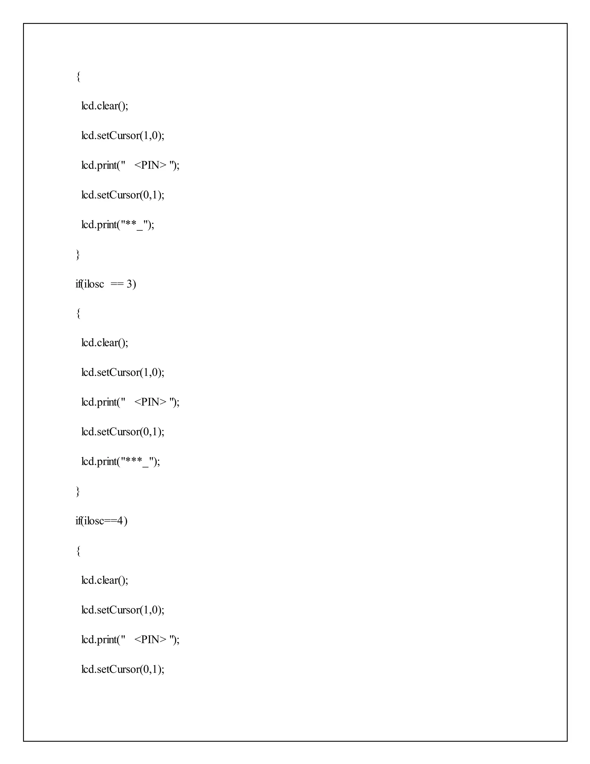
![const byte COLS=4; char keys[ROWS][COLS]={ {'1','2','3','A'}, {'4','5','6','B'}, {'7','8','9','C'}, {'*','0','#','D'} }; byte rowPins[ROWS]={5,4,3,2}; byte colPins[COLS]={9,8,7,6}; Keypad keypad=Keypad(makeKeymap(keys),rowPins,colPins,ROWS,COLS); void setup() { keypad.addEventListener(keypadEvent); Serial.begin(9600); pinMode(ledRed,OUTPUT); pinMode(ledGreen,OUTPUT); lcd.begin(16,2); lcd.setCursor(1,0); lcd.print("PLEASE ENTER PIN"); } void loop()](https://image.slidesharecdn.com/embeddedsystemdevelopment-ay-151020054325-lva1-app6892/75/Embedded-system-development-Arduino-UNO-38-2048.jpg)
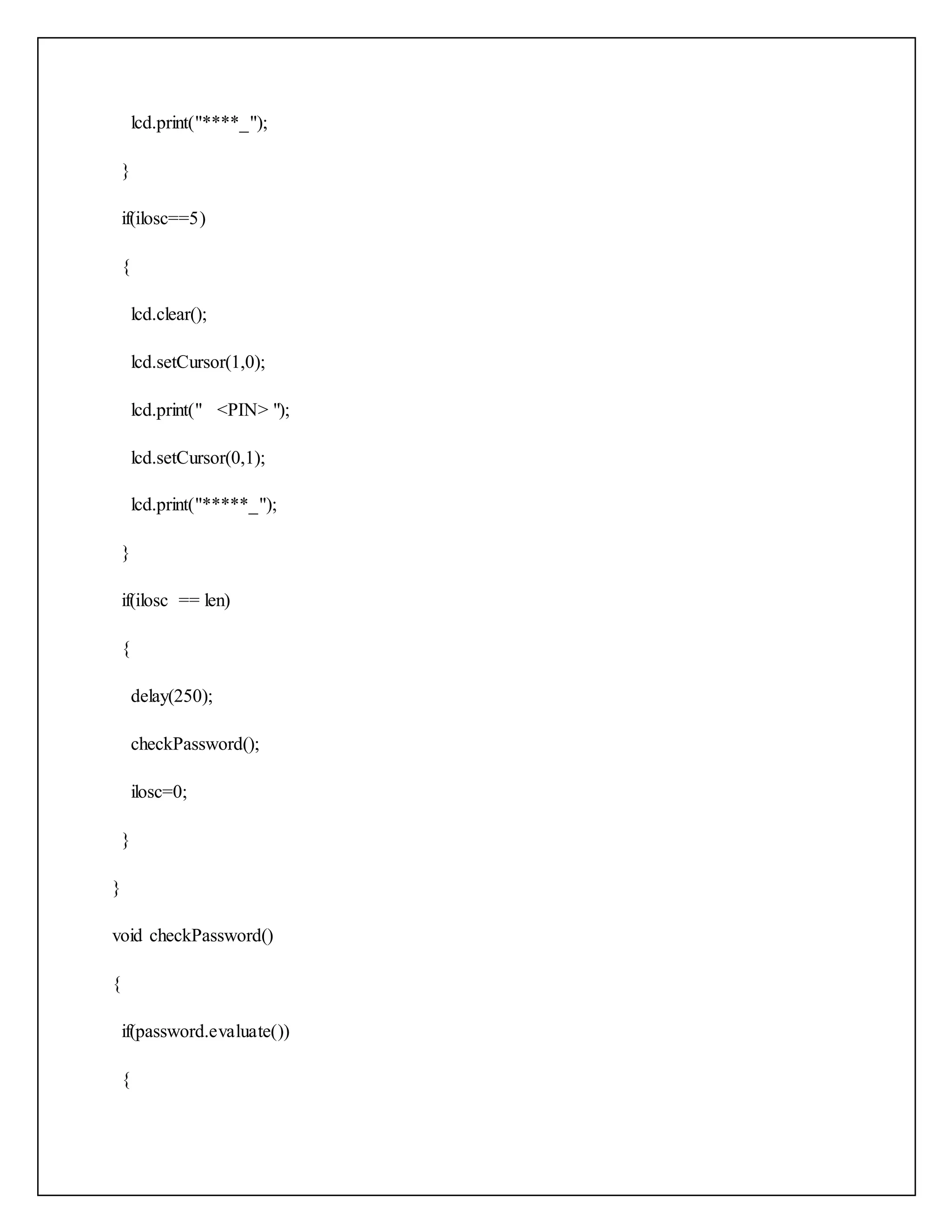
![//led lcd.begin(16,2); lcd.println("RFID World"); pinMode(6,OUTPUT); //convert binary to human readable form SPI.begin(); //initialise or activate rfid //as setup execute only once digitalWrite(6,LOW); //initialise the rfid myRFID.AddicoreRFID_Init(); } unsigned char structure[16]; unsigned char status; void loop(){ uchar status; uchar str[MAX_LEN]; status=myRFID.AddicoreRFID_Request(PICC_REQIDL,str); status=myRFIDAddicoreRFID_Anticoll(str); if(status==MI_OK){ lcd.setCursor(0,1);](https://image.slidesharecdn.com/embeddedsystemdevelopment-ay-151020054325-lva1-app6892/75/Embedded-system-development-Arduino-UNO-47-2048.jpg)
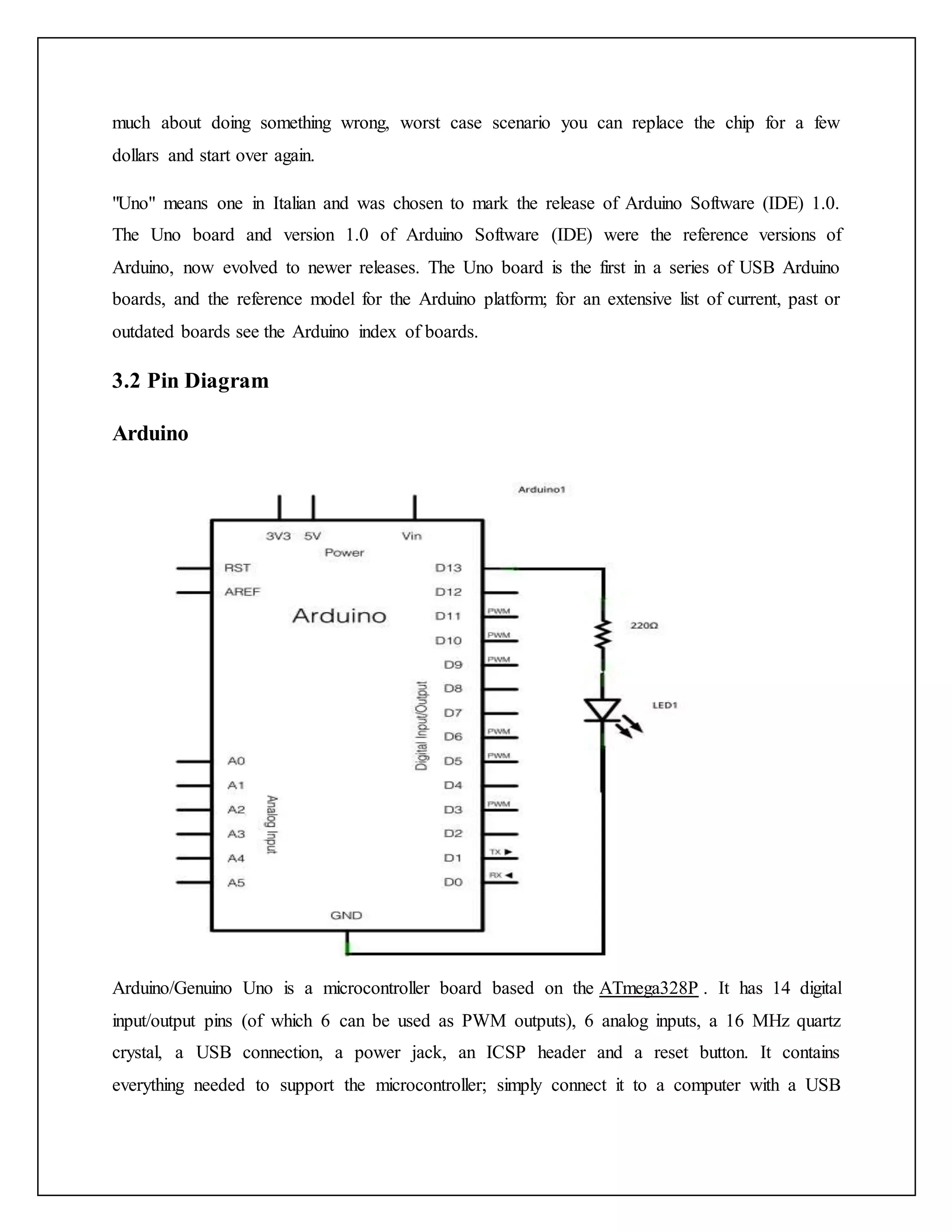
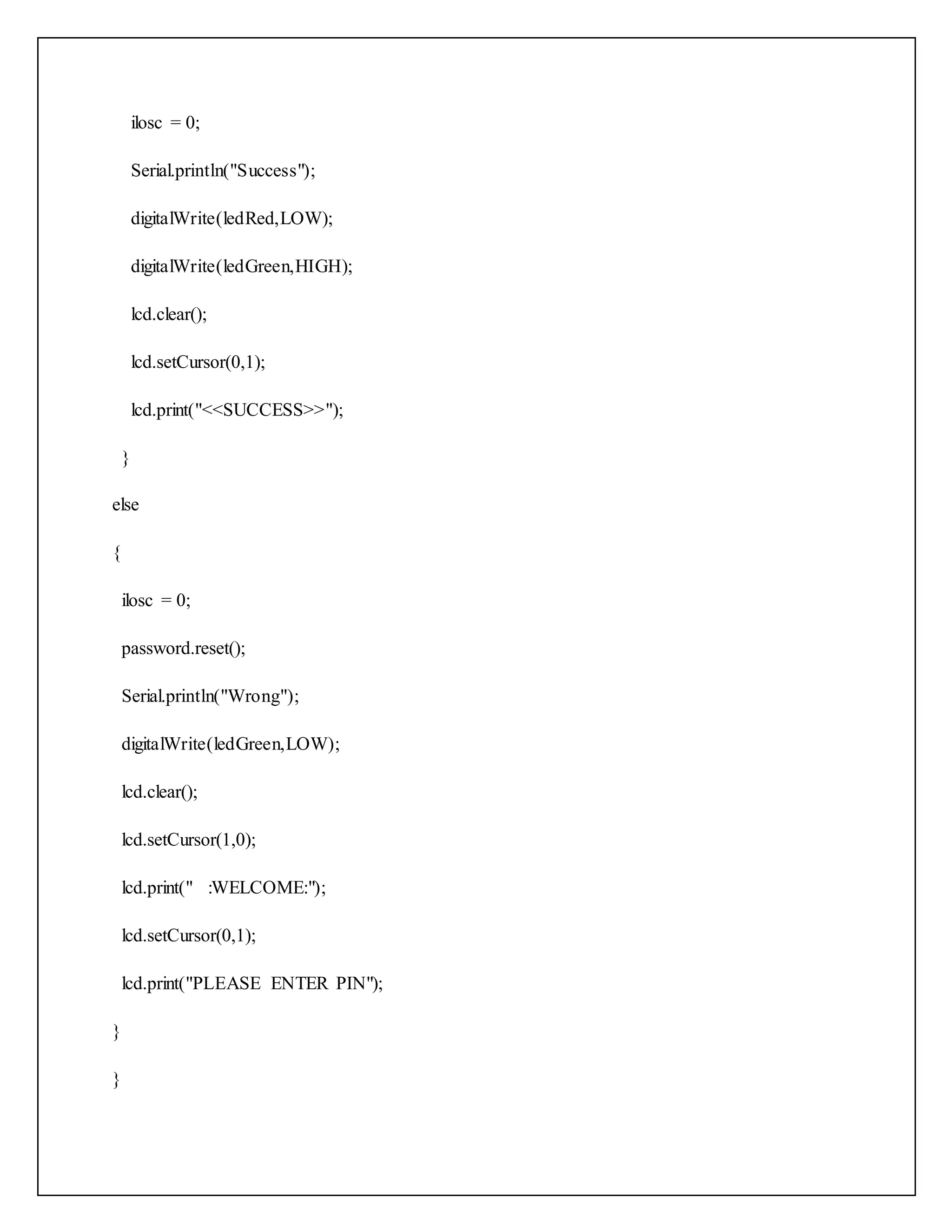
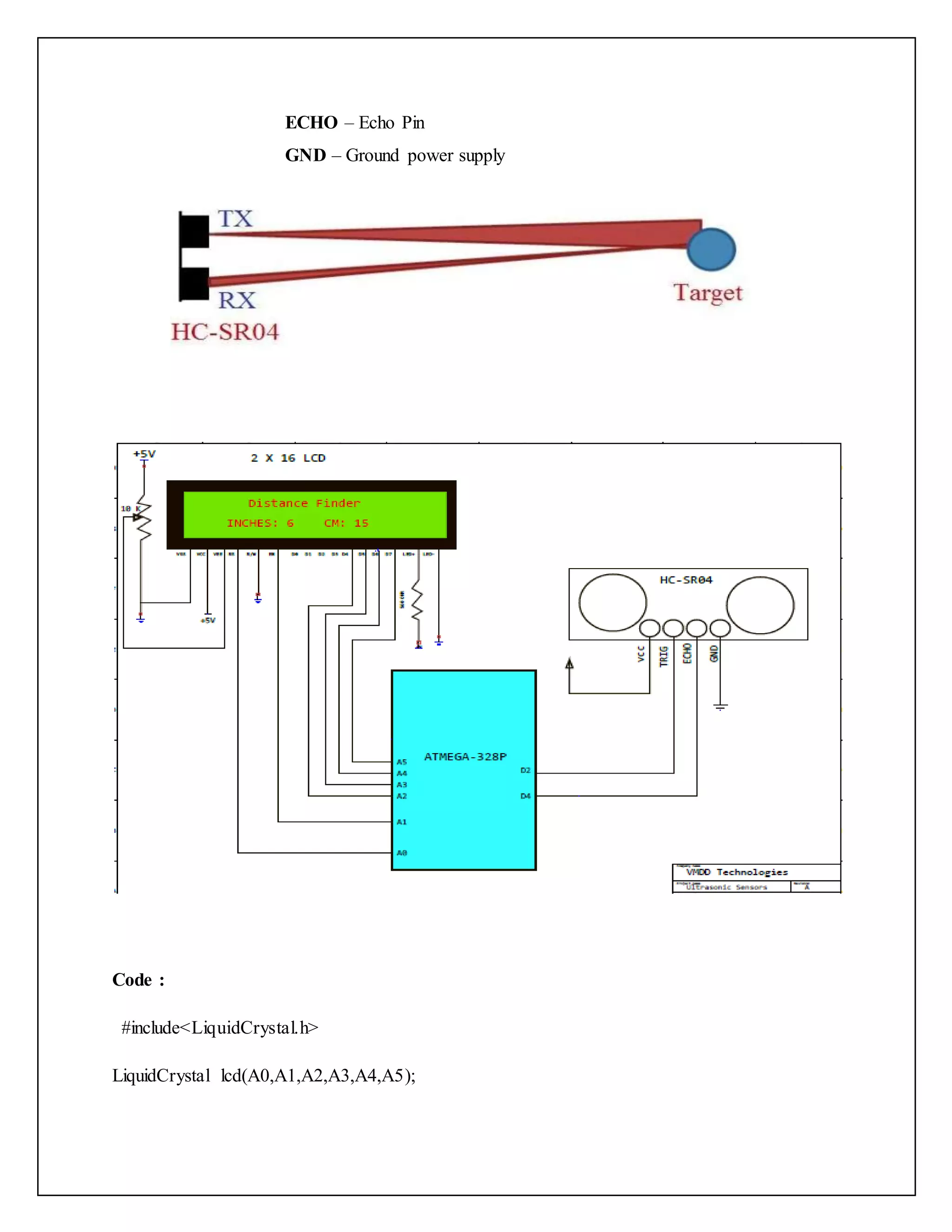
![lcd.print("Tag ID:"); lcd.setCursor(8,1); lcd.print(str[0]); digitalWrite(6,HIGH); delay(1000); digitalWrite(6,LOW); } myRFID.AddicoreRFID_Halt(); } 5.6 Ultrasonic Sensors Components Required: 1.) Custom Board 2.) POT-METER(10k) 3.) 2 x 16 LCD 4.) Breadboard 5.) Resistor 560 ohm 6.) Couple of Jumper Wire 7.) HC-SR04 Interfacing of ultrasonic Sensors withAtmega-328p HC-SR04 Ultrasonic distance sensors is a popular and low cost solution for non-contact distance measurement function. It is able to measure distances from 1cm to 400cm with an accuracy of about 3mm. This module includes ultrasonic transmitter, ultrasonic receiver and its control circuit. HC-SR04 module has 4 pins : VCC – 5V power supply TRIG – Trigger Pin](https://image.slidesharecdn.com/embeddedsystemdevelopment-ay-151020054325-lva1-app6892/75/Embedded-system-development-Arduino-UNO-48-2048.jpg)


This document provides an overview of embedded systems and discusses Arduino. It defines an embedded system as a combination of hardware and software designed for a specific function. Embedded systems are commonly based on microcontrollers and are optimized for their dedicated tasks. Examples of embedded systems include appliances, vehicles, medical devices, and more. The document then discusses the Arduino platform as an example of an embedded system and how it can be programmed using its IDE software.