The document provides a comprehensive introduction to Arduino, detailing its specifications, features, and various applications including motor control and data reading. It explores comparisons with other platforms like Raspberry Pi, as well as communication protocols such as SPI and I2C. Additionally, it discusses programming with different compilers and IDEs, optimizing performance through techniques like DMA, and practical examples of using Arduino for projects.

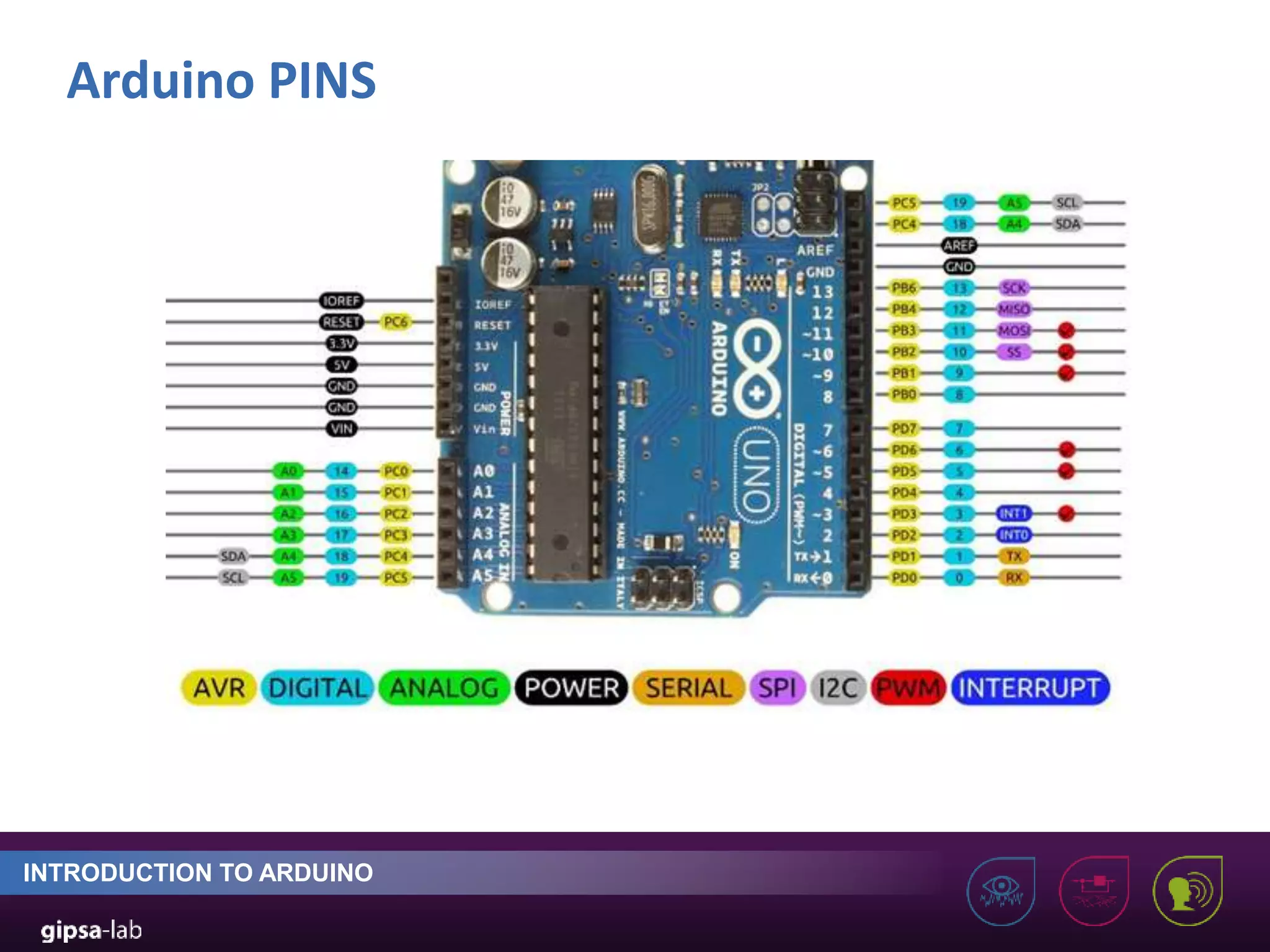
![Arduino GPIO INTRODUCTION TO ARDUINO General-Purpose Input Output (GPIO) 14 digital and 6 analog pins ca be used for both input and output pinMode (3, OUTPUT) //set as output digitalWrite (3, HIGH) //set 3,3V value digitalRead(pin) //read state digitalRead(pin) // ADC 5v -> [0..1023]](https://image.slidesharecdn.com/arduino-220706183540-28b9db2d/75/How-to-use-an-Arduino-10-2048.jpg)
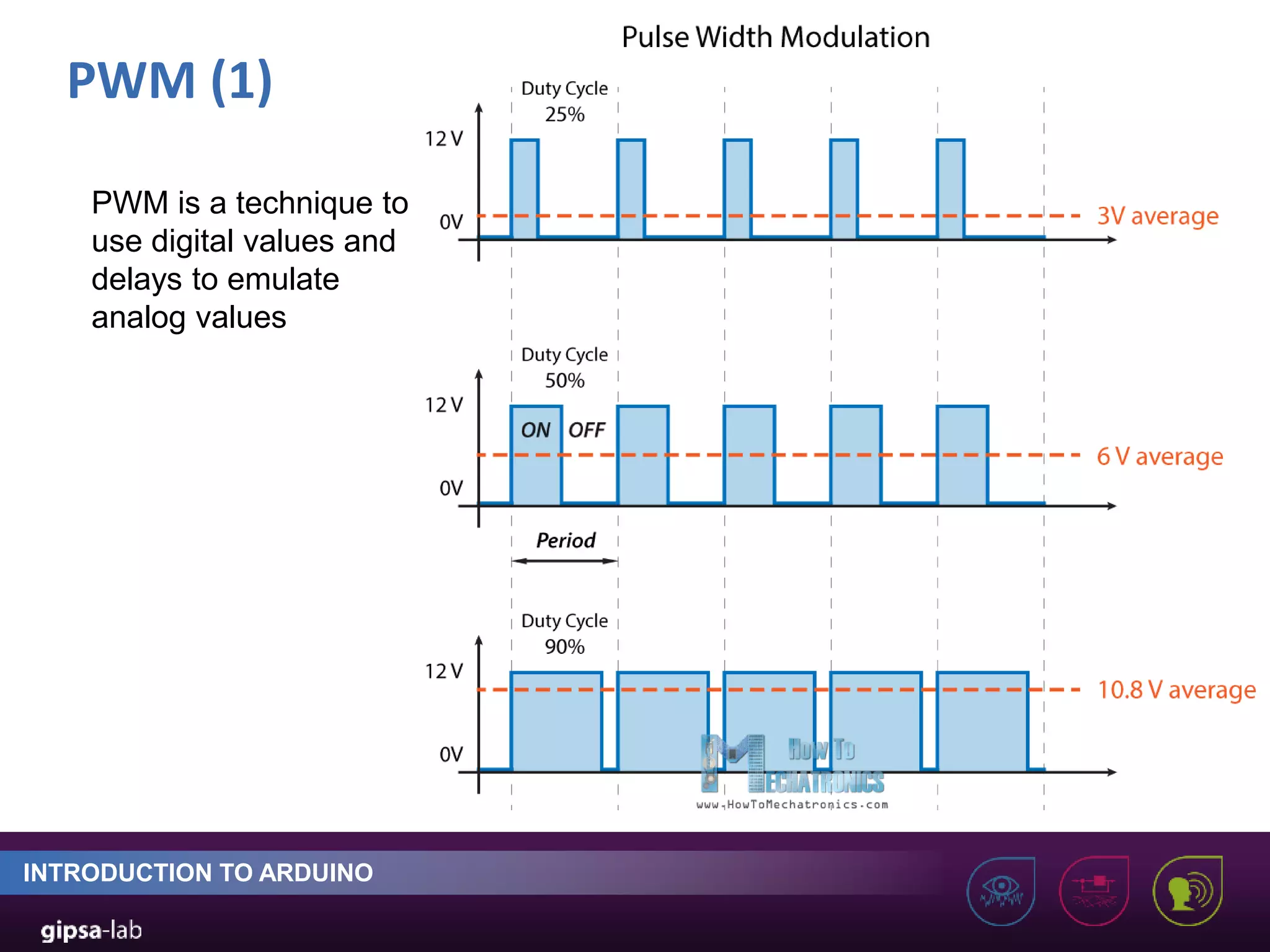
![DC motor control with Arduino (3) INTRODUCTION TO ARDUINO We use PWM in the range of [0 255]. So if want 3V out of 12V maximum then we need to send the value of 255/4 on the control pin 255 corresponds to 12 volts](https://image.slidesharecdn.com/arduino-220706183540-28b9db2d/75/How-to-use-an-Arduino-19-2048.jpg)