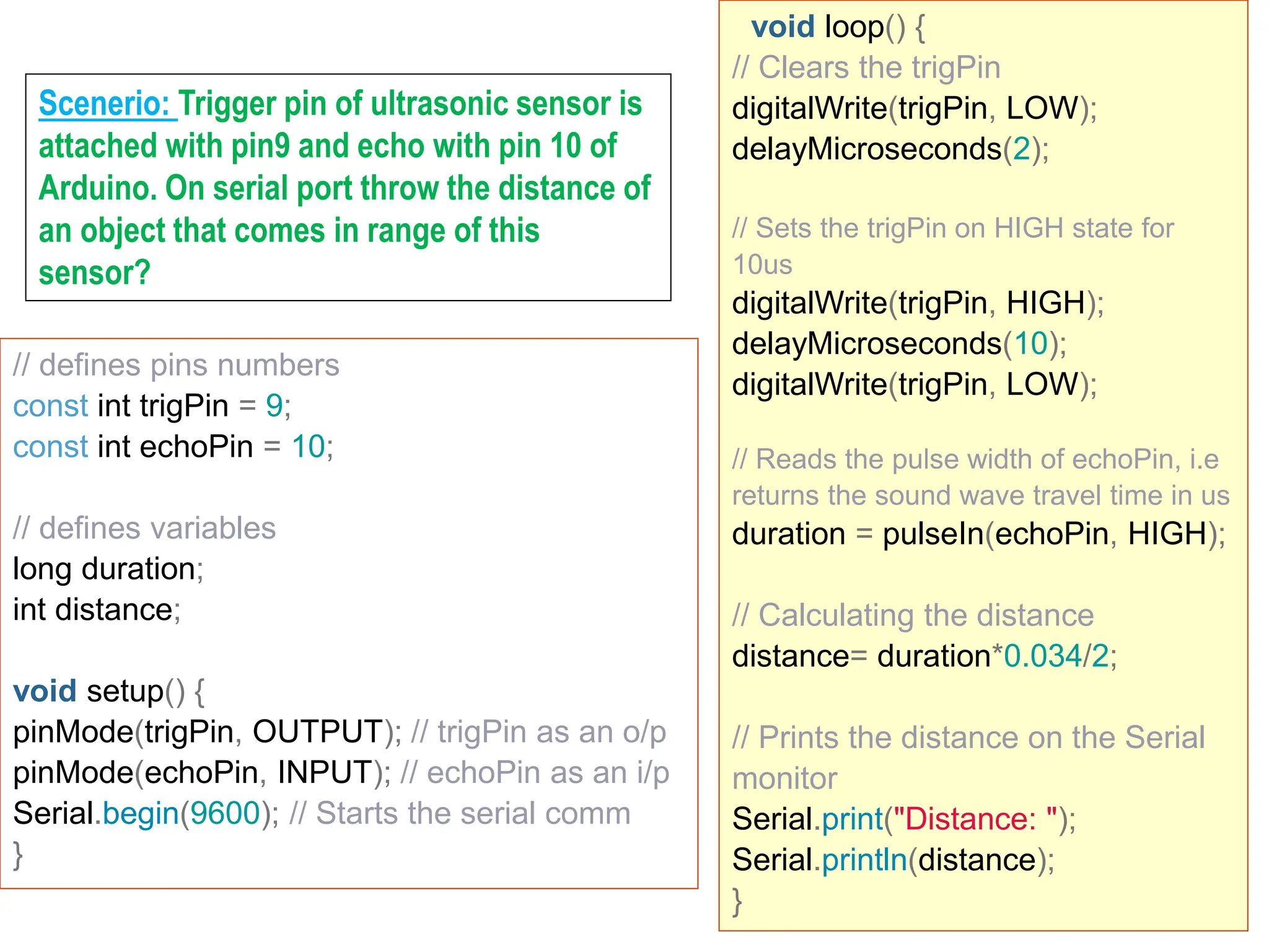
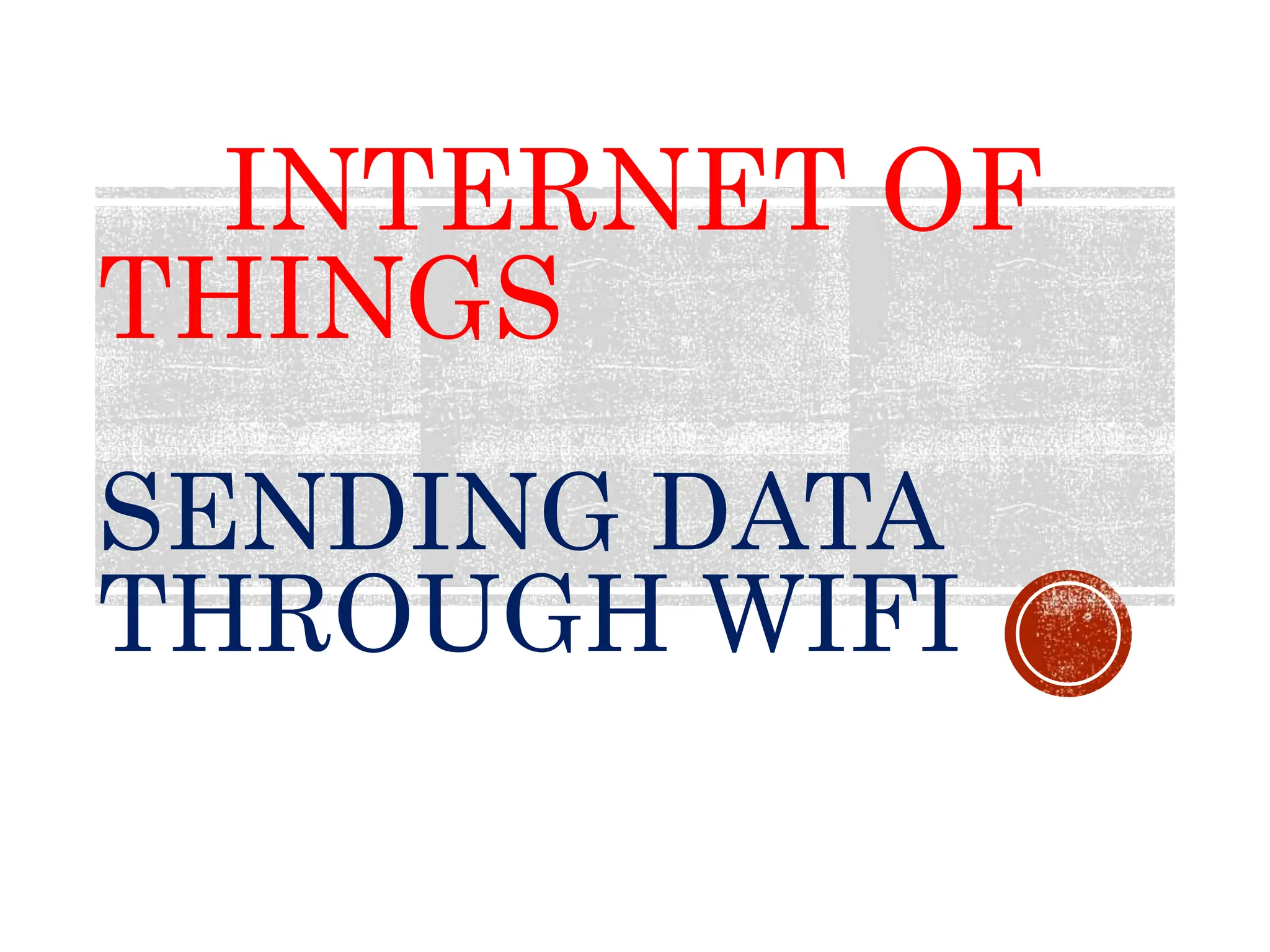
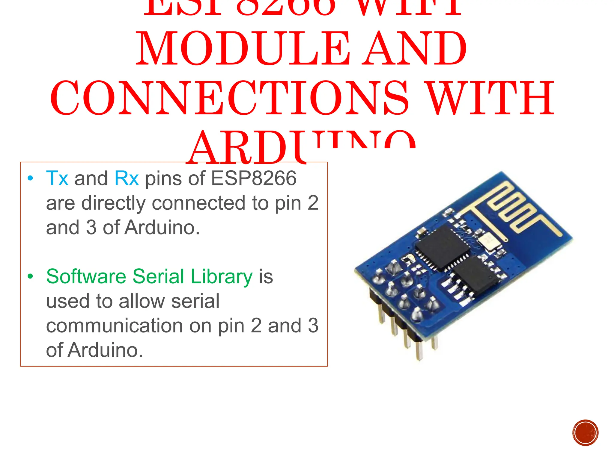
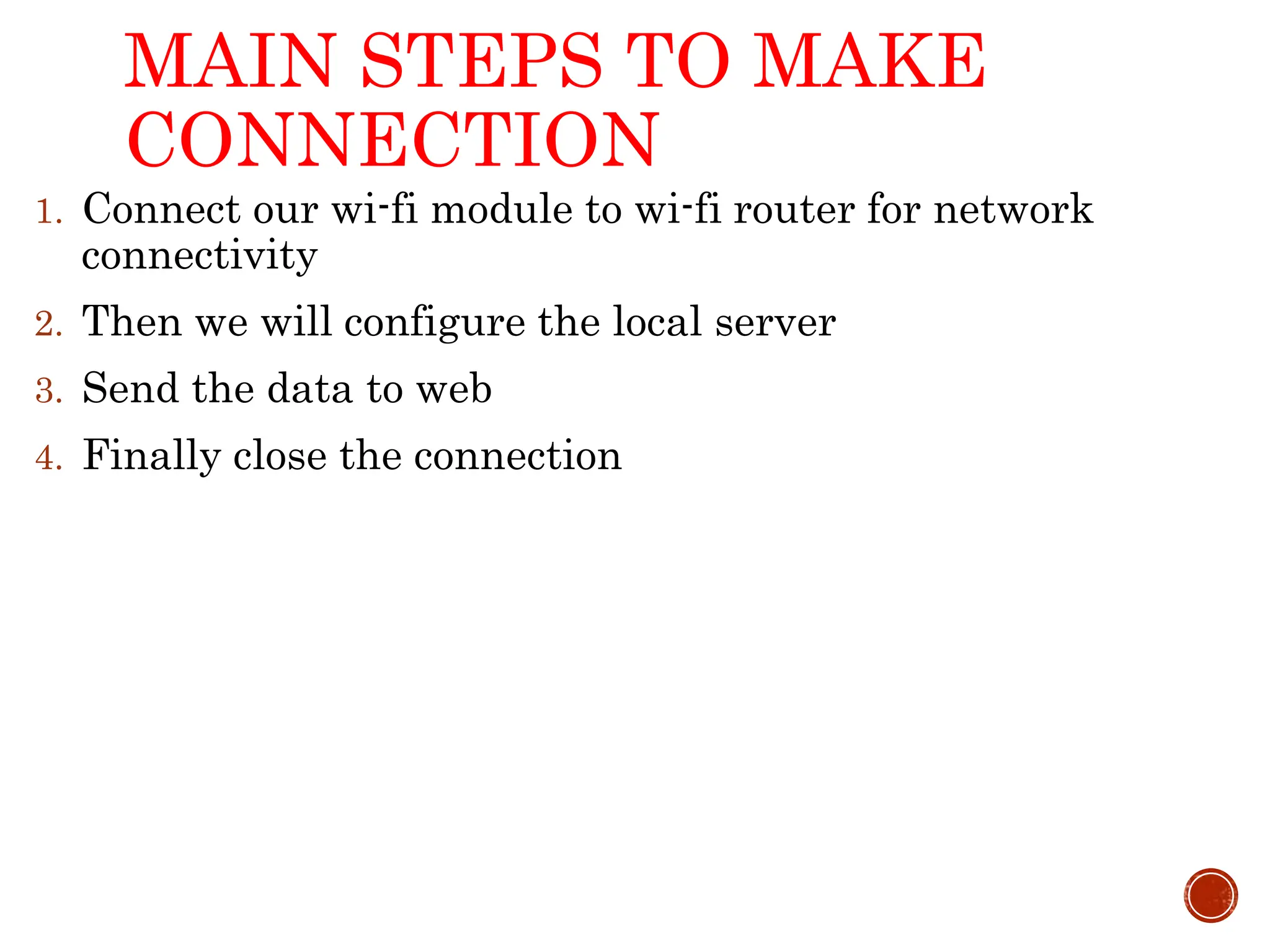
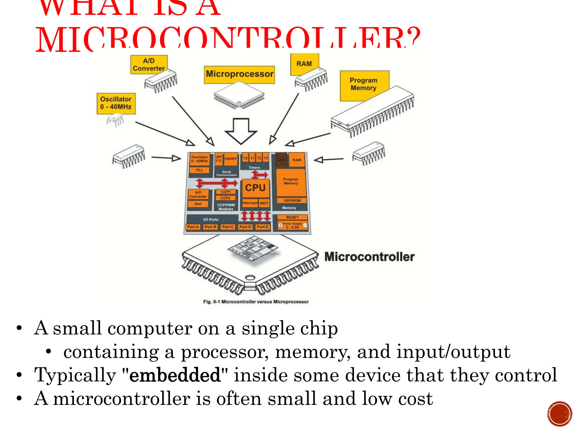
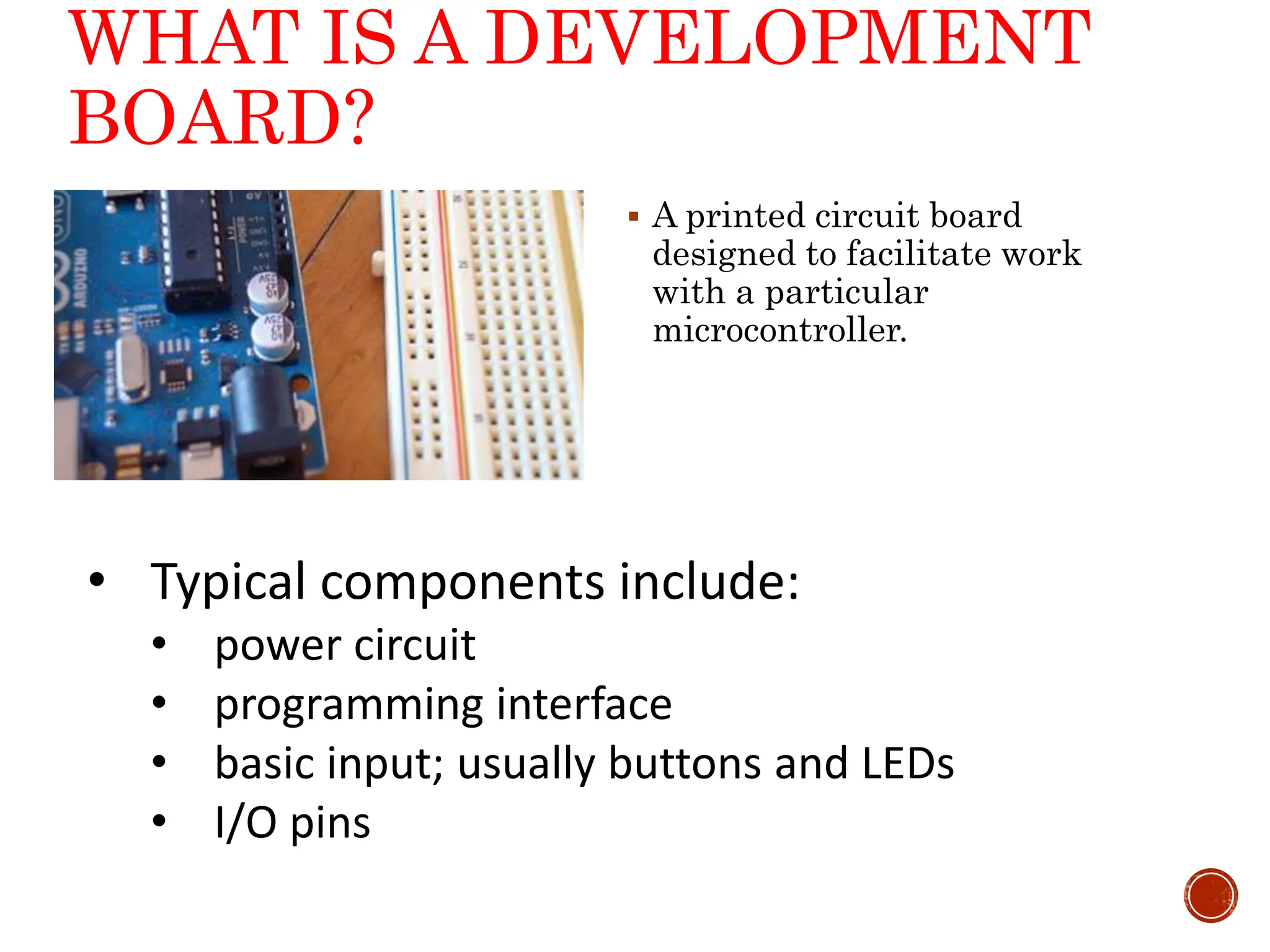
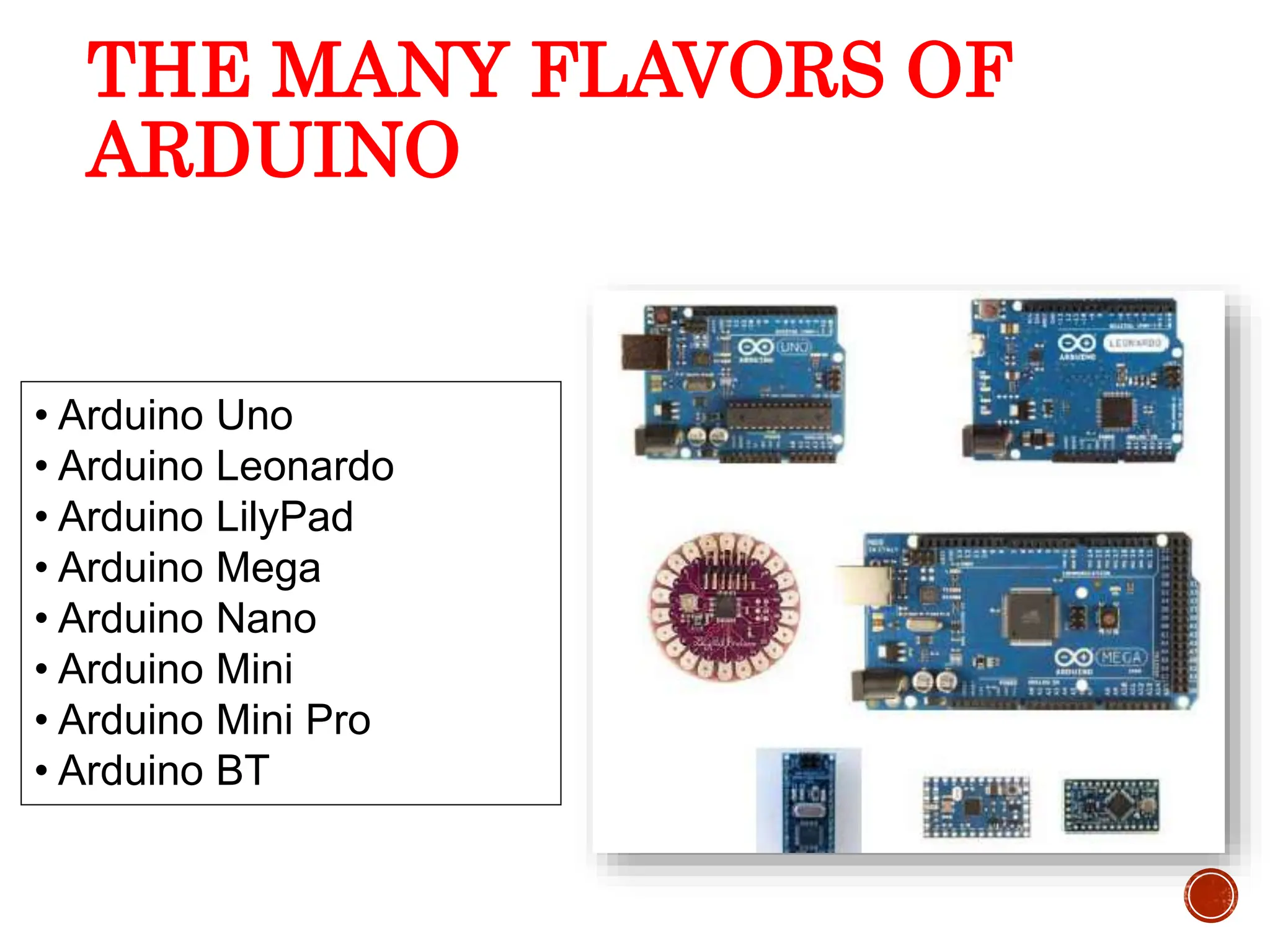
The document explains microcontrollers and development boards, specifically focusing on Arduino models and their programming environment. It covers programming basics, digital and analog input/output functions, and includes examples for controlling LEDs, motors, and sensors. Additionally, it introduces serial communication, external interrupts, and the functionality of various sensors such as ultrasonic and piezo sensors.
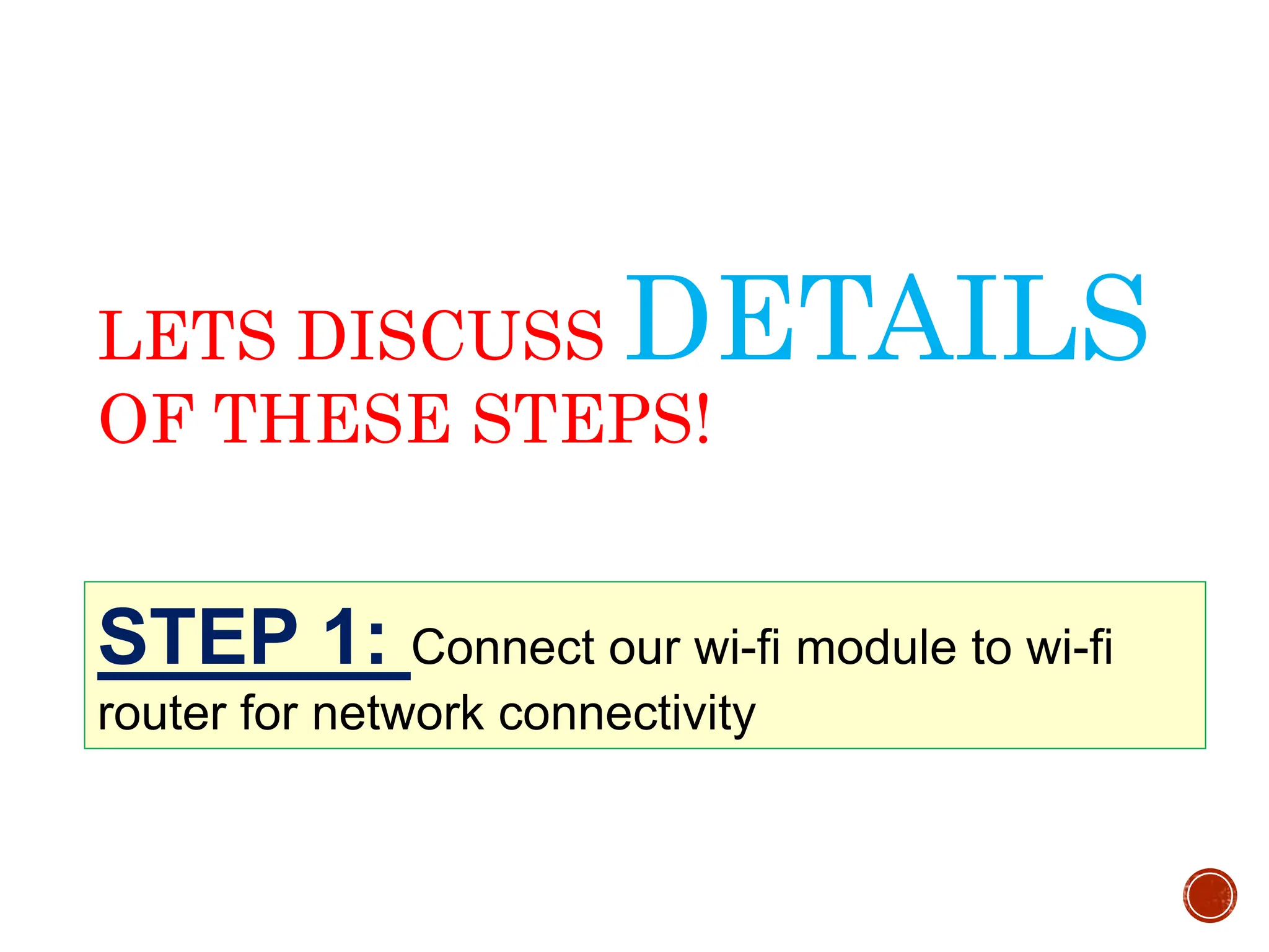
![5 USB 7-12v Adapter External DC input Supplies Analog Input Pins Digital I/O Pins Pins with ~ are PWM [Analog Output] GND Transmitter/Receiver Serial Connection Microcontroller ATmega328 Operating Voltage 5V Input Voltage (recommended)7-12V Input Voltage (limits)6-20V Digital I/O Pins 14 (of which 6 provide PWM output) Analog Input Pins 6 DC Current per I/O Pin 40 mA DC Current for 3.3V Pin 50 mA Reset Button Analog Reference 16Mhz Crystal](https://image.slidesharecdn.com/01introtothearduino-240626221028-c3474e0b/75/01-Intro-to-the-Arduino-and-it-s-basics-ppt-5-2048.jpg)
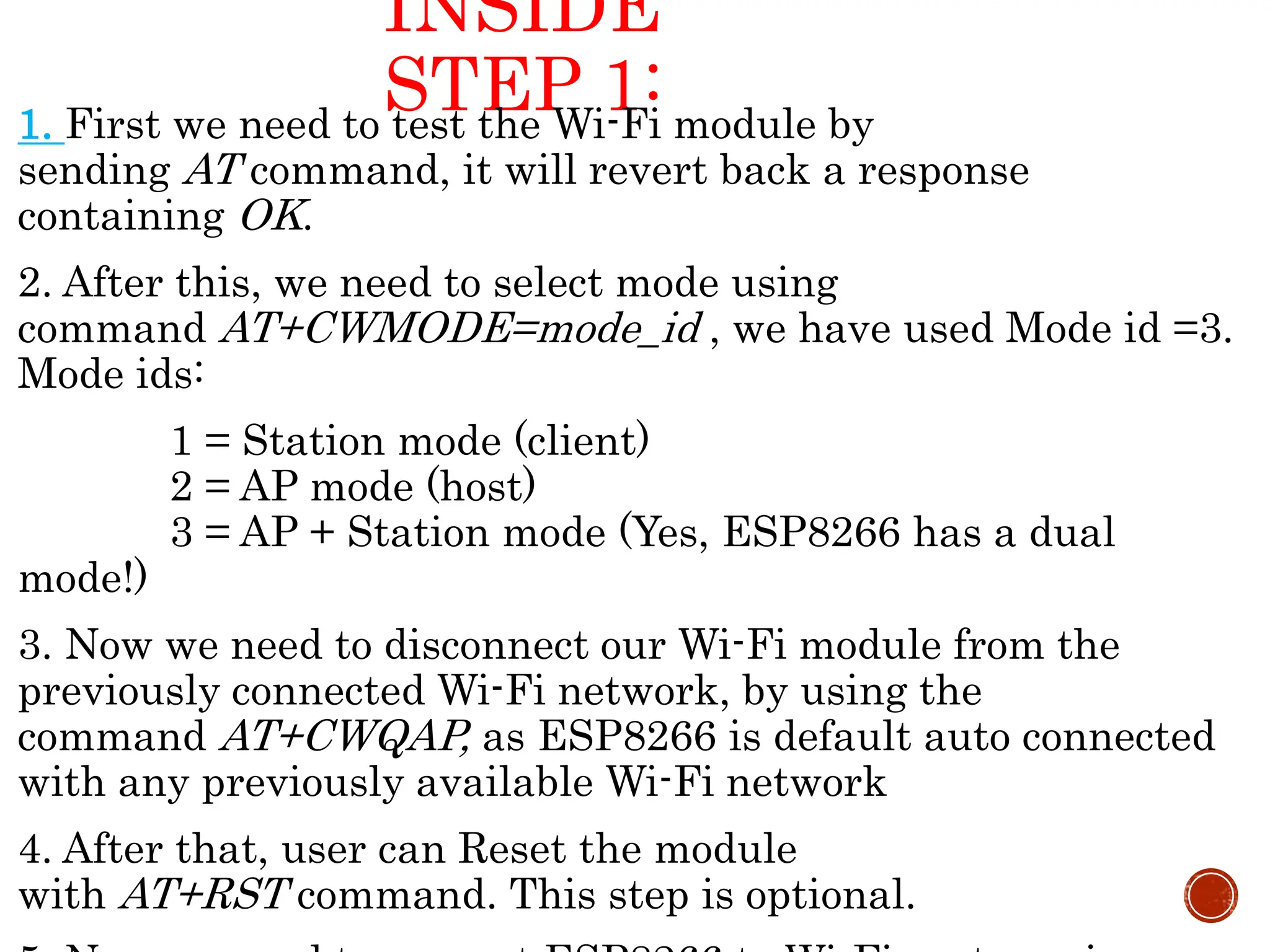
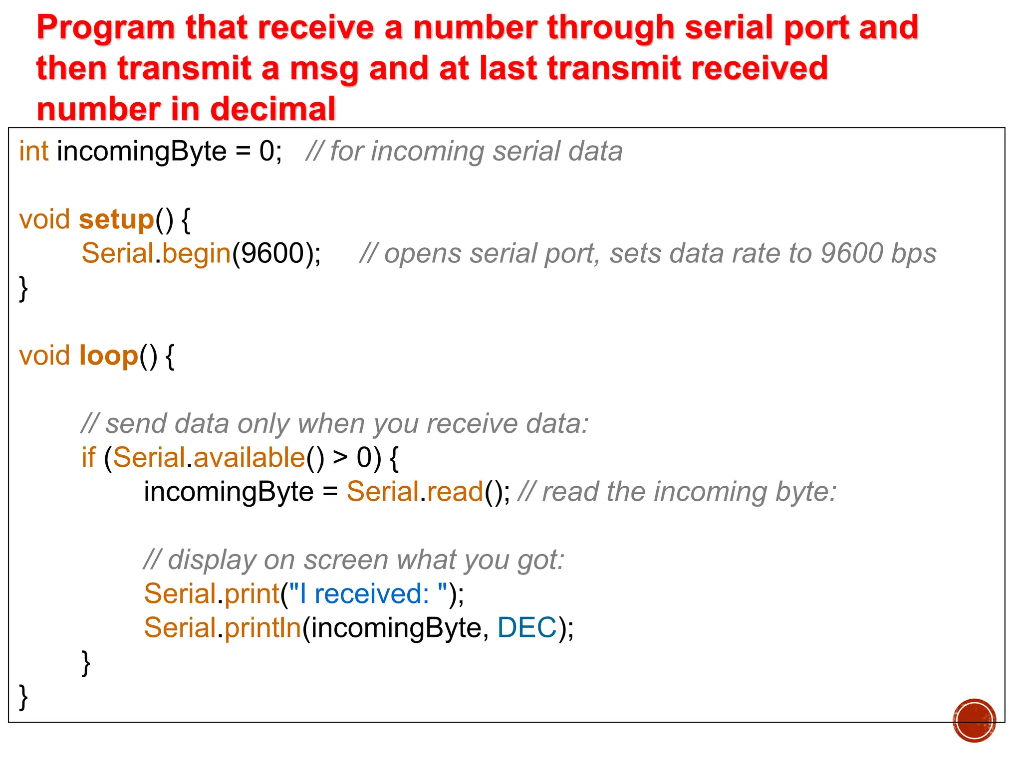
![const int kPinLeds[] = {2,3,4,5}; // LEDs connected to pins 2-5 void setup() { for(int i = 0; i<4; i++) pinMode(kPinLeds[i], OUTPUT); // make LED pins 2-5 o/p } void loop() { for(int i = 0; i < 4; i++) // LEDs switch on from left to right { digitalWrite(kPinLeds[i], HIGH); delay(100); } for(int i = 3; i >= 0; i--) // LED switch off from right to left { digitalWrite(kPinLeds[i], LOW); delay(100); } } Program that switch on LEDs connected to pin2-5 from left to right and then switch off on reverse order](https://image.slidesharecdn.com/01introtothearduino-240626221028-c3474e0b/75/01-Intro-to-the-Arduino-and-it-s-basics-ppt-17-2048.jpg)

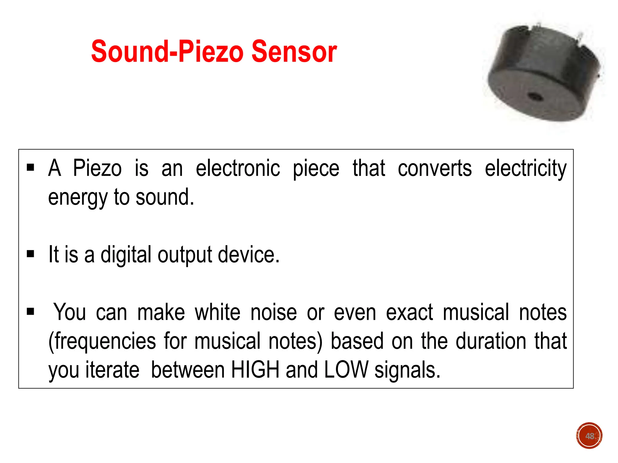
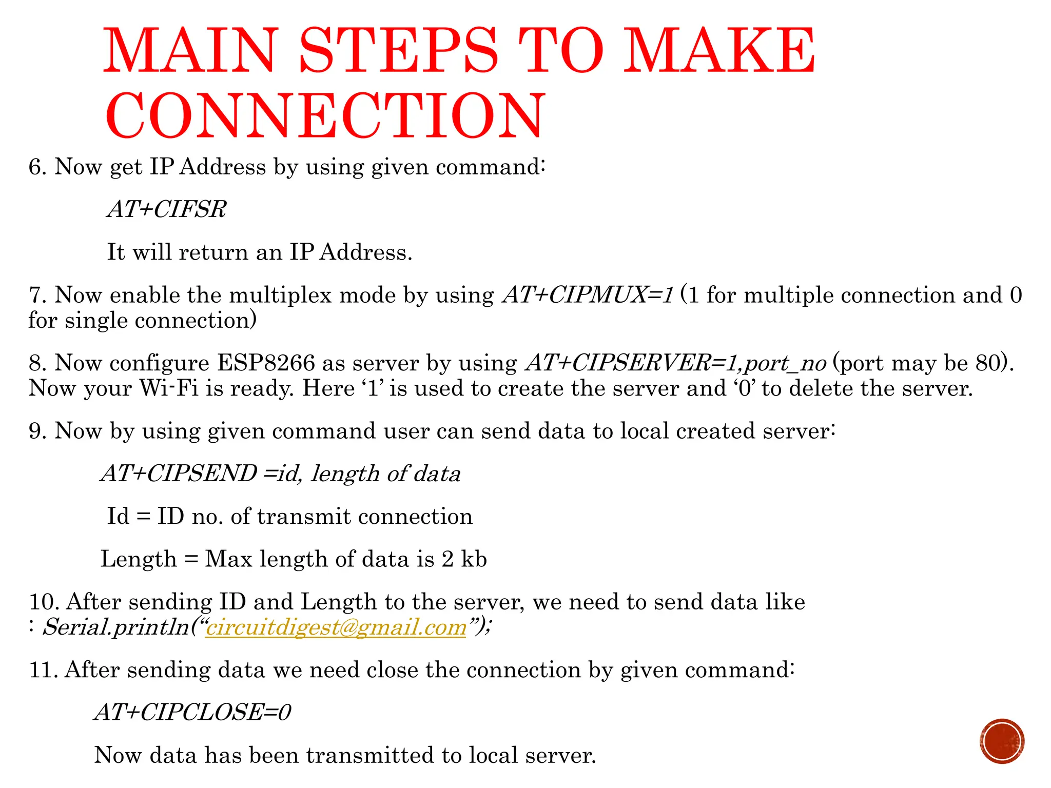
![Arduino- Digital Output-Sound-Piezo // Program to play musical tones using piezo sensor attached with pin 13 int freqs[] = {1915, 1700, 1519, 1432, 1275, 1136, 1014, 956}; void setup(){ pinMode(13,OUTPUT); } void loop(){ for(int i=0;i<8;i++) //iterating through notes { for(int j=0;j<1000;j++) //the time span that each note is being played { digitalWrite(13,HIGH); delayMicroseconds(freqs[i]); //delay in microseconds digitalWrite(13,LOW); delayMicroseconds(freqs[i]); } } 49](https://image.slidesharecdn.com/01introtothearduino-240626221028-c3474e0b/75/01-Intro-to-the-Arduino-and-it-s-basics-ppt-49-2048.jpg)