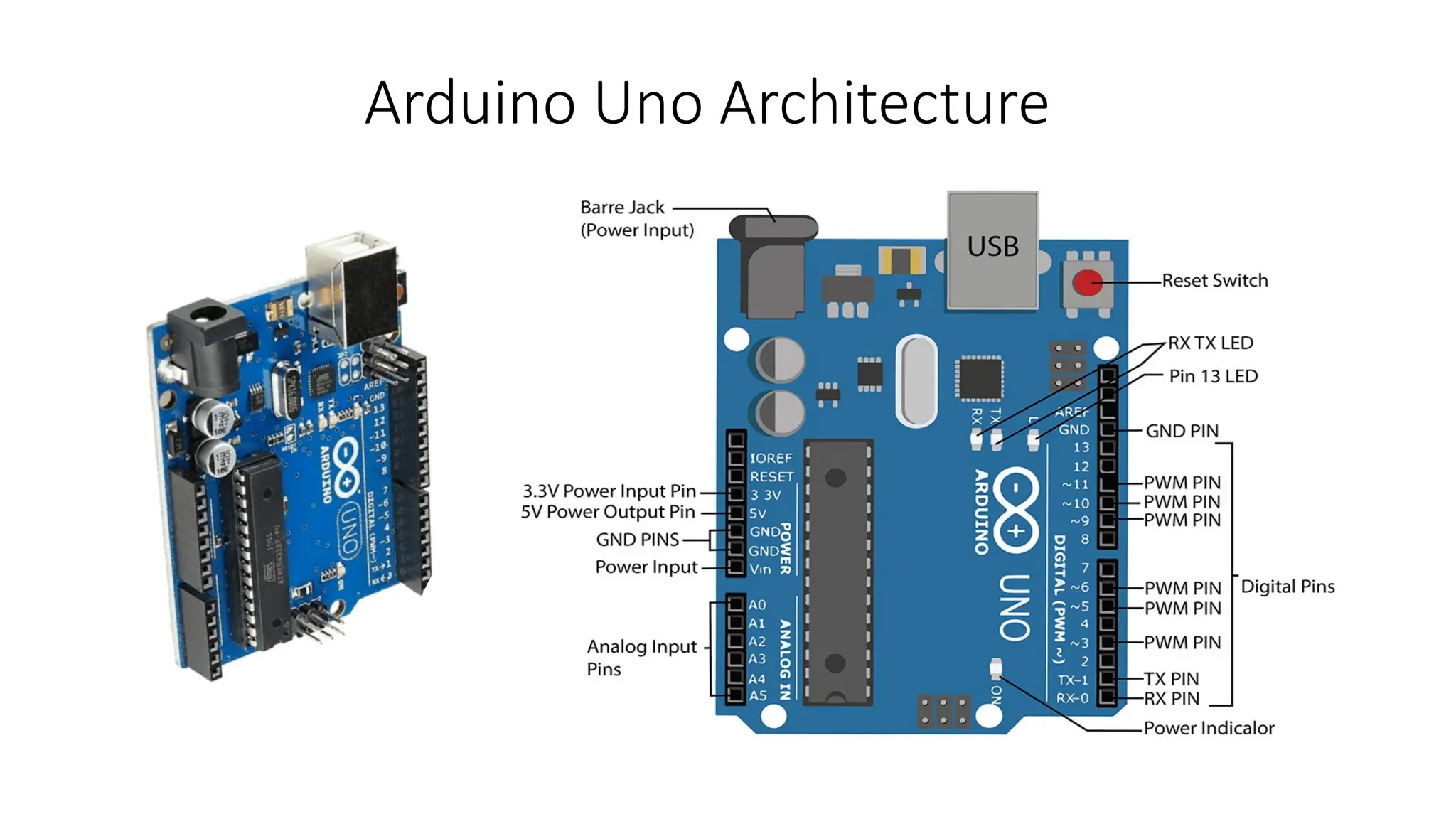
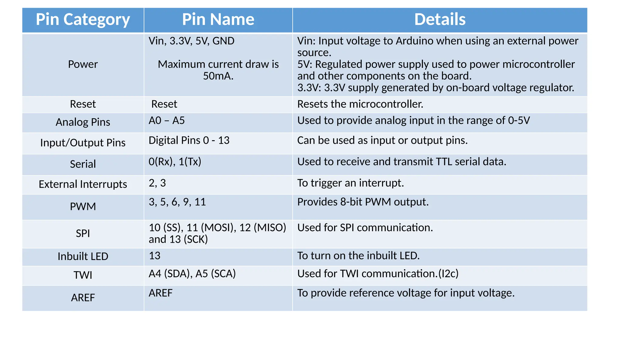
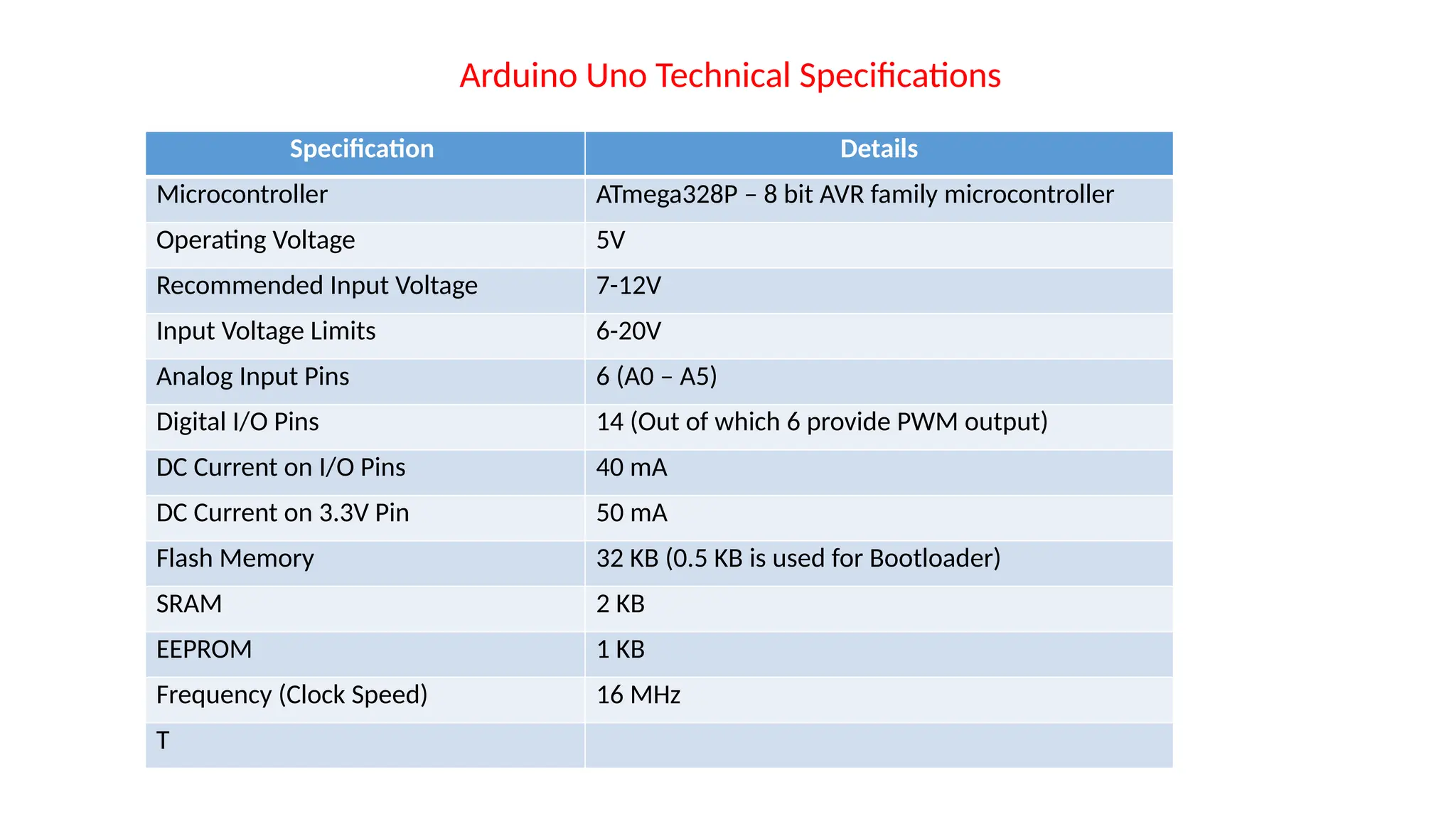
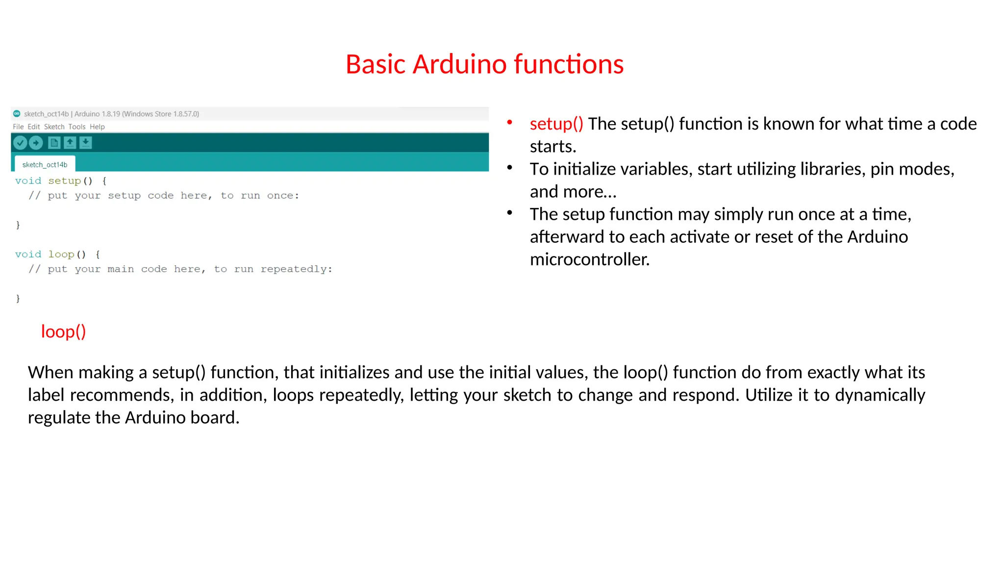
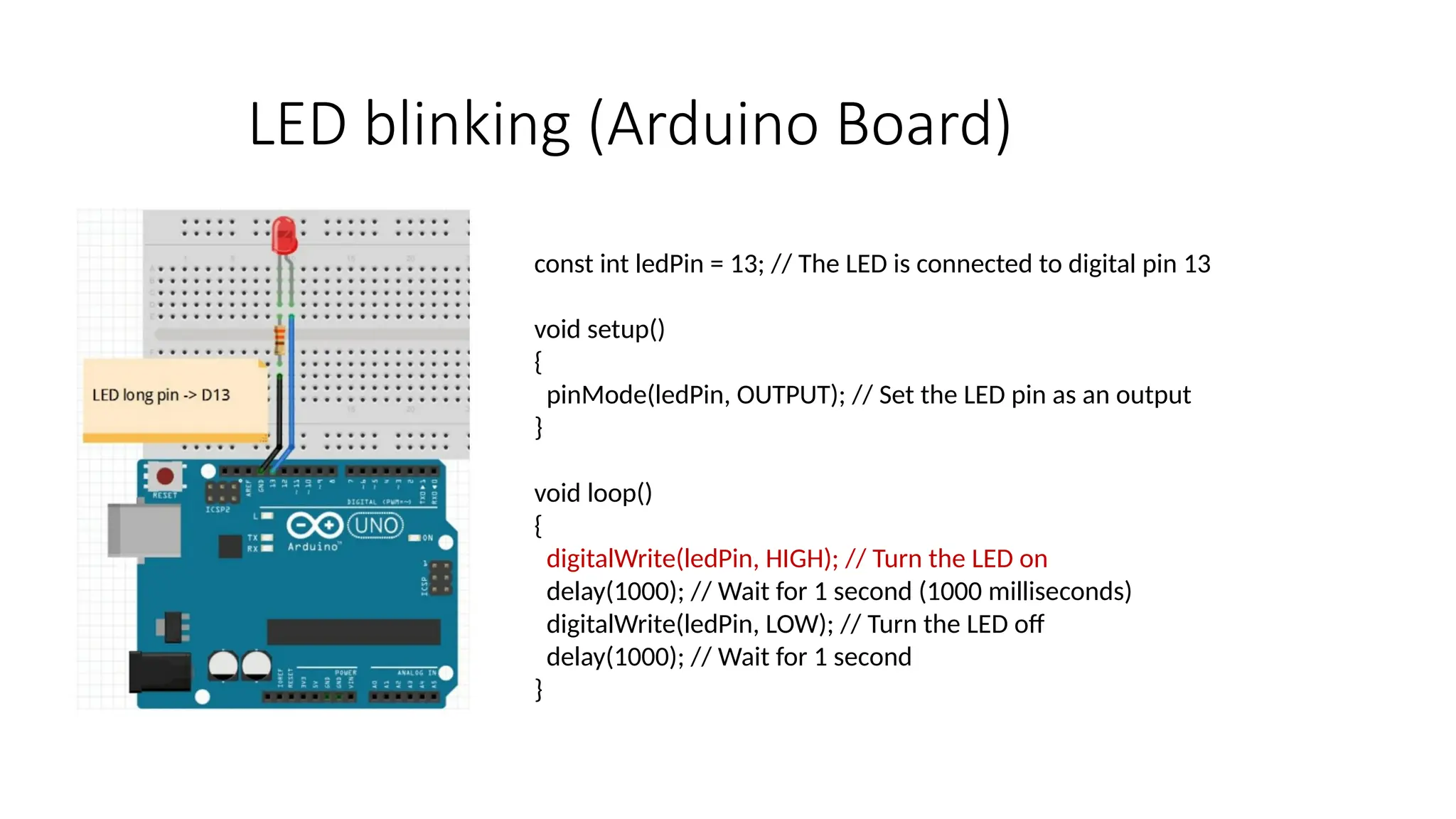
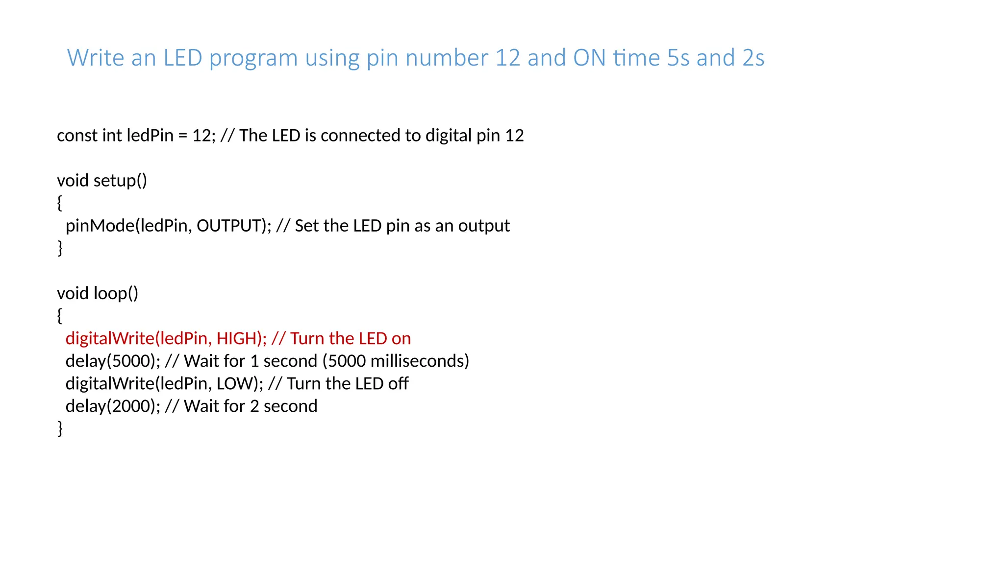
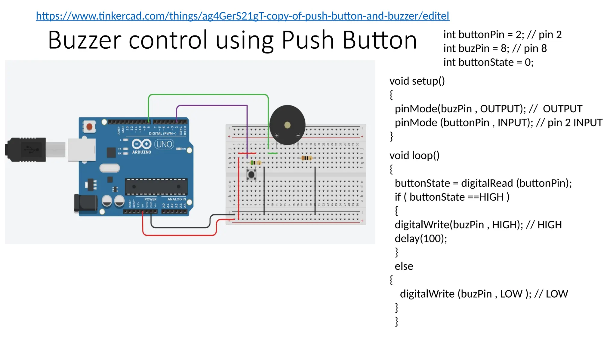
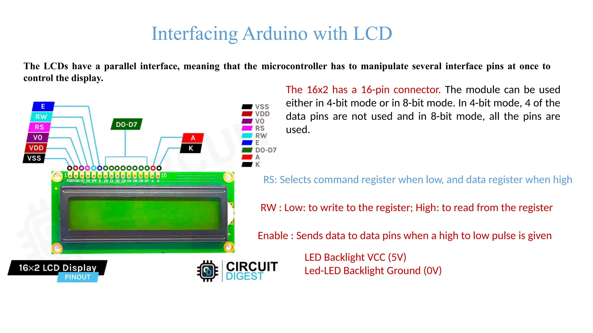
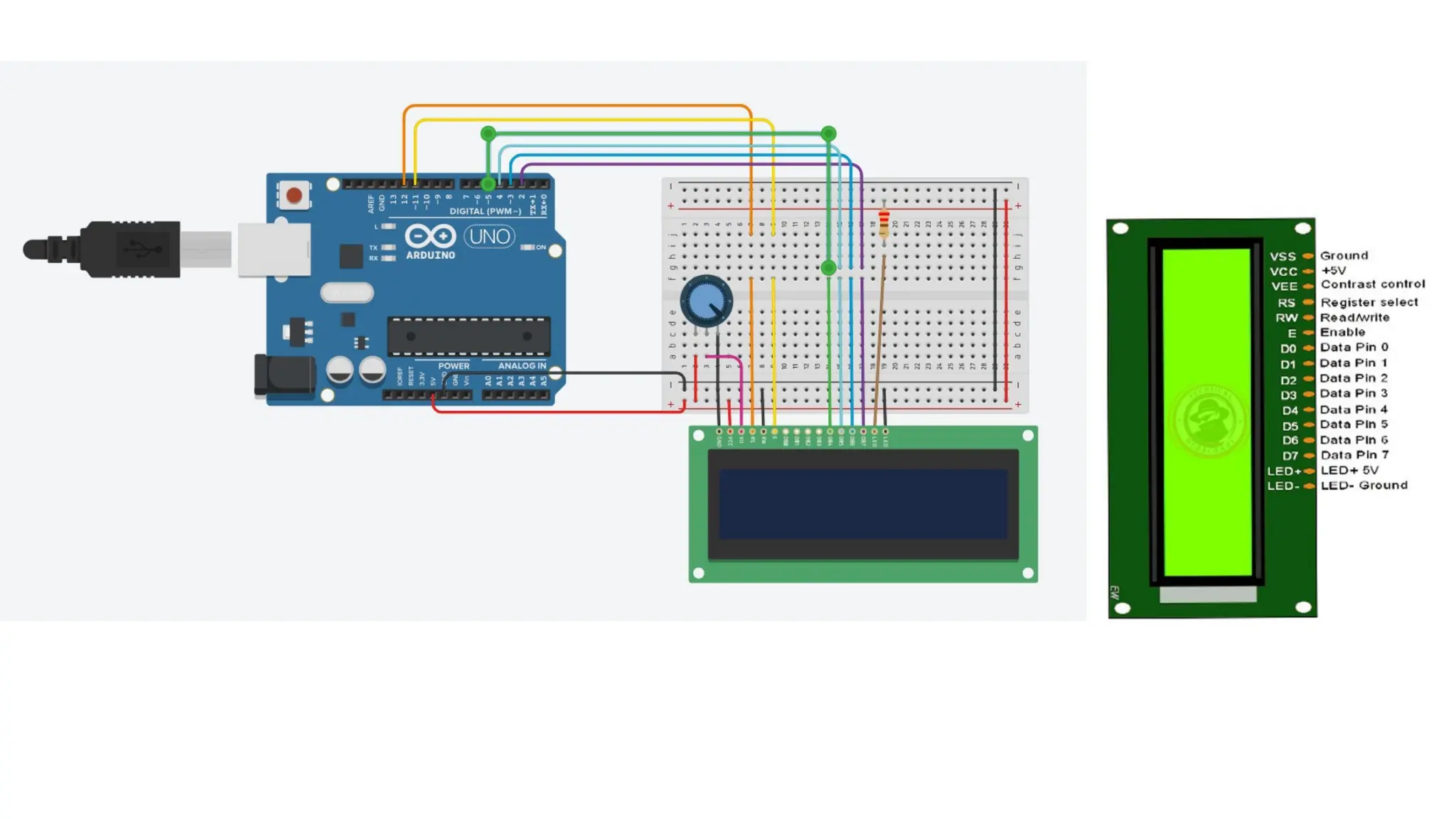
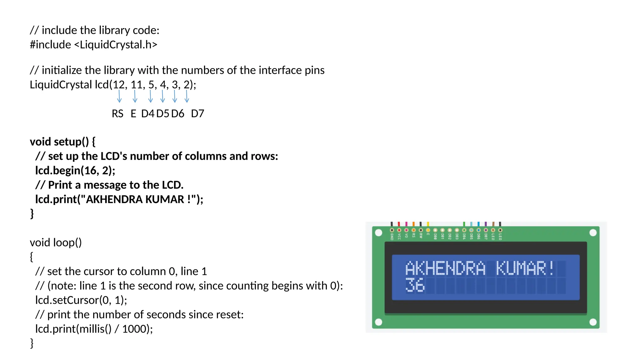
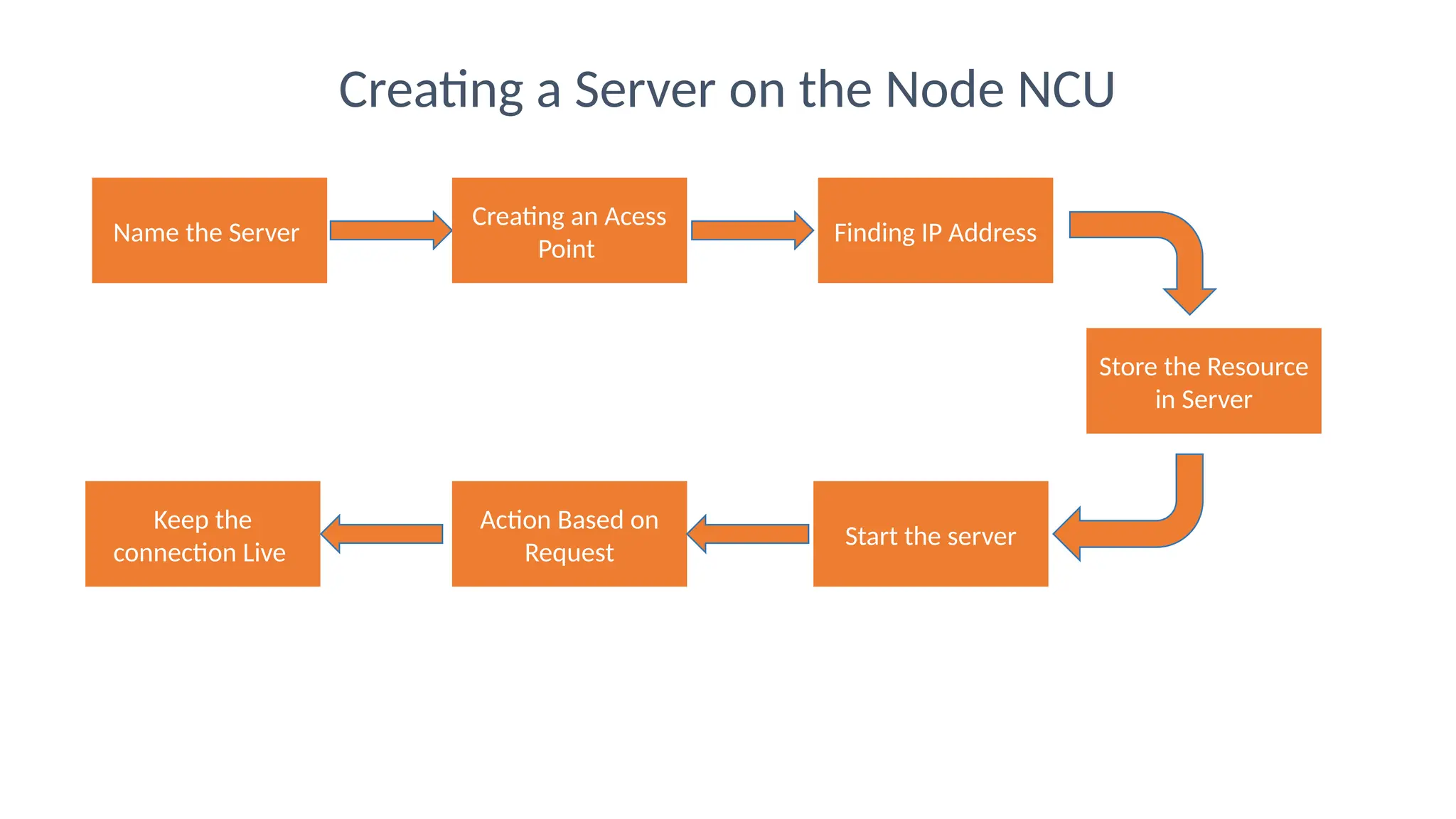
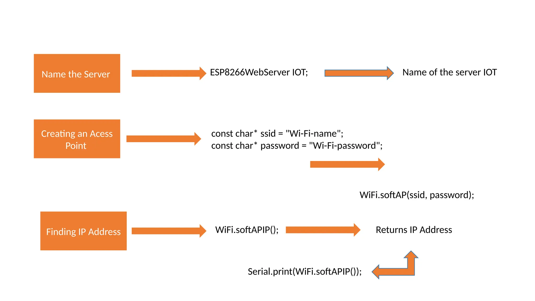
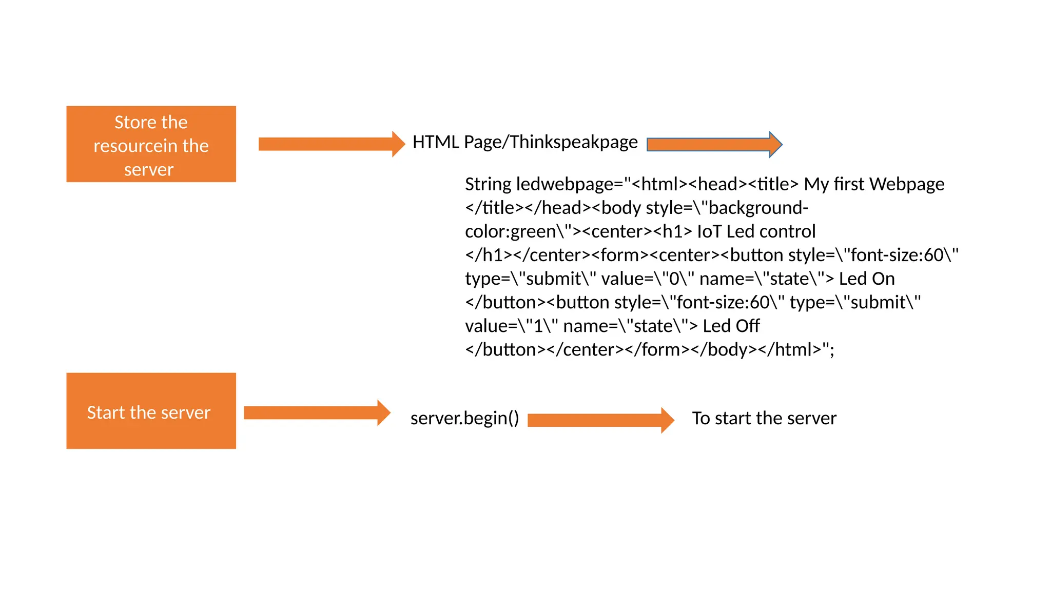
UNIT-IV Arduino Simulation Environment, Arduino Uno Architecture, Setup the IDE, Writing Arduino Software, Arduino Libraries, Basics of Embedded programming for Arduino, Interfacing LED, push button and buzzer with Arduino, Interfacing Arduino with LCD
Arduino Uno Architecture
Pin Category Pin Name Details Power Vin, 3.3V, 5V, GND Maximum current draw is 50mA. Vin: Input voltage to Arduino when using an external power source. 5V: Regulated power supply used to power microcontroller and other components on the board. 3.3V: 3.3V supply generated by on-board voltage regulator. Reset Reset Resets the microcontroller. Analog Pins A0 โ€“ A5 Used to provide analog input in the range of 0-5V Input/Output Pins Digital Pins 0 - 13 Can be used as input or output pins. Serial 0(Rx), 1(Tx) Used to receive and transmit TTL serial data. External Interrupts 2, 3 To trigger an interrupt. PWM 3, 5, 6, 9, 11 Provides 8-bit PWM output. SPI 10 (SS), 11 (MOSI), 12 (MISO) and 13 (SCK) Used for SPI communication. Inbuilt LED 13 To turn on the inbuilt LED. TWI A4 (SDA), A5 (SCA) Used for TWI communication.(I2c) AREF AREF To provide reference voltage for input voltage.
Arduino Uno Technical Specifications Specification Details Microcontroller ATmega328P โ€“ 8 bit AVR family microcontroller Operating Voltage 5V Recommended Input Voltage 7-12V Input Voltage Limits 6-20V Analog Input Pins 6 (A0 โ€“ A5) Digital I/O Pins 14 (Out of which 6 provide PWM output) DC Current on I/O Pins 40 mA DC Current on 3.3V Pin 50 mA Flash Memory 32 KB (0.5 KB is used for Bootloader) SRAM 2 KB EEPROM 1 KB Frequency (Clock Speed) 16 MHz T
Comparision between Uno/ ESP8266 Boards
Basic Arduino functions โ€ข setup() The setup() function is known for what time a code starts. โ€ข To initialize variables, start utilizing libraries, pin modes, and moreโ€ฆ โ€ข The setup function may simply run once at a time, afterward to each activate or reset of the Arduino microcontroller. loop() When making a setup() function, that initializes and use the initial values, the loop() function do from exactly what its label recommends, in addition, loops repeatedly, letting your sketch to change and respond. Utilize it to dynamically regulate the Arduino board.
Arduino Library Functions The pinMode() function in Arduino is used to configure a specific digital I/O pin on a microcontroller, like the ESP8266/Arsuino Uno, for a particular mode of operation. The two primary modes are input and output. Input Mode: When you set a pin to input mode, you configure it to read external data. It might be connected to a sensor, switch, or any other external device that provides an electrical signal to the microcontroller. pinMode(2, INPUT); // Set digital pin 2 as an input int sensorValue = digitalRead(2); // Read the value from digital pin 2 Output Mode: When you set a pin to output mode, you configure it to send electrical signals to external devices like LEDs, relays, or other components. You can use digitalWrite() to set the pin's state to HIGH (5V) or LOW (0V). pinMode(3, OUTPUT); // Set digital pin 3 as an output digitalWrite(3, HIGH); // Set digital pin 3 to HIGH (5V) It can be used to set the voltage level (HIGH or LOW) of a specific digital pin
delay() delay() Function can be used for pauses the codes for the certain amount of duration (in milliseconds) stated as parameter. (1 seconds is equal to 1000 milliseconds.) Analog I/O Reads the value from the specified analog pin. Arduino boards contain a multichannel, 10-bit analog to digital converter. This means that it will map input voltages between 0 and the operating voltage(5V or 3.3V) into integer values between 0 and 1023 analogRead() int sensorValue = analogRead(pin); int sensorPin = A0; // Analog pin connected to the sensor *A0 through A5 are labelled on the board, A6 through A11 are respectively available on pins 4, 6, 8, 9, 10, and 12
analogWrite() Writes an analog value (PWM wave) to a pin. Can be used to light a LED at varying brightnesses or drive a motor at various speeds. After a call to analogWrite(), the pin will generate a steady rectangular wave of the specified duty cycle until the next call to analogWrite() (or a call to digitalRead() or digitalWrite()) on the same pin. analogWrite(pin, value); In Arduino, the analogReference() function is used to set the reference voltage for analog-to-digital conversions on a microcontroller.
abs(x): Returns the absolute value of a number x. For example, abs(-5) returns 5. sqrt(x): Returns the square root of a number x. For example, sqrt(25) returns 5. pow(base, exponent): Returns base raised to the power of exponent. For example, pow(2, 3) returns 8. exp(x): Returns the value of e (Euler's number) raised to the power of x. For example, exp(1) returns the approximate value of 2.71828. log(x): Returns the natural logarithm (base e) of x. For example, log(10) returns the approximate value of 2.30259. log10(x): Returns the base-10 logarithm of x. For example, log10(100) returns 2. sin(x), cos(x), tan(x): These functions return the sine, cosine, and tangent of an angle x (in radians), respectively. radians(deg): Converts degrees to radians. degrees(rad): Converts radians to degrees. min(a, b): Returns the minimum of two numbers a and b. max(a, b): Returns the maximum of two numbers a and b.
Blink an LED Arduino Uno โ€ข Wired Connection โ€ข No network ESP8266 โ€ข Local connection โ€ข Same Network ESP8266 โ€ข Internet โ€ข Cloud server(Thinkspeak)
LED blinking (Arduino Board) const int ledPin = 13; // The LED is connected to digital pin 13 void setup() { pinMode(ledPin, OUTPUT); // Set the LED pin as an output } void loop() { digitalWrite(ledPin, HIGH); // Turn the LED on delay(1000); // Wait for 1 second (1000 milliseconds) digitalWrite(ledPin, LOW); // Turn the LED off delay(1000); // Wait for 1 second }
Write an LED program using pin number 12 and ON time 5s and 2s const int ledPin = 12; // The LED is connected to digital pin 12 void setup() { pinMode(ledPin, OUTPUT); // Set the LED pin as an output } void loop() { digitalWrite(ledPin, HIGH); // Turn the LED on delay(5000); // Wait for 1 second (5000 milliseconds) digitalWrite(ledPin, LOW); // Turn the LED off delay(2000); // Wait for 2 second }
Buzzer control using Push Button int buttonPin = 2; // pin 2 int buzPin = 8; // pin 8 int buttonState = 0; https://www.tinkercad.com/things/ag4GerS21gT-copy-of-push-button-and-buzzer/editel void setup() { pinMode(buzPin , OUTPUT); // OUTPUT pinMode (buttonPin , INPUT); // pin 2 INPUT } void loop() { buttonState = digitalRead (buttonPin); if ( buttonState ==HIGH ) { digitalWrite(buzPin , HIGH); // HIGH delay(100); } else { digitalWrite (buzPin , LOW ); // LOW } }
Interfacing Arduino with LCD The LCDs have a parallel interface, meaning that the microcontroller has to manipulate several interface pins at once to control the display. The 16x2 has a 16-pin connector. The module can be used either in 4-bit mode or in 8-bit mode. In 4-bit mode, 4 of the data pins are not used and in 8-bit mode, all the pins are used. RS: Selects command register when low, and data register when high RW : Low: to write to the register; High: to read from the register Enable : Sends data to data pins when a high to low pulse is given LED Backlight VCC (5V) Led-LED Backlight Ground (0V)
// include the library code: #include <LiquidCrystal.h> // initialize the library with the numbers of the interface pins LiquidCrystal lcd(12, 11, 5, 4, 3, 2); void setup() { // set up the LCD's number of columns and rows: lcd.begin(16, 2); // Print a message to the LCD. lcd.print("AKHENDRA KUMAR !"); } void loop() { // set the cursor to column 0, line 1 // (note: line 1 is the second row, since counting begins with 0): lcd.setCursor(0, 1); // print the number of seconds since reset: lcd.print(millis() / 1000); } RS E D4D5D6 D7
Name the Server Creating an Acess Point Finding IP Address Store the Resource in Server Start the server Action Based on Request Keep the connection Live Creating a Server on the Node NCU
Name the Server ESP8266WebServer IOT; Name of the server IOT Creating an Acess Point const char* ssid = "Wi-Fi-name"; const char* password = "Wi-Fi-password"; WiFi.softAP(ssid, password); Finding IP Address WiFi.softAPIP(); Returns IP Address Serial.print(WiFi.softAPIP());
Store the resourcein the server HTML Page/Thinkspeakpage Start the server server.begin() To start the server String ledwebpage="<html><head><title> My first Webpage </title></head><body style="background- color:green"><center><h1> IoT Led control </h1></center><form><center><button style="font-size:60" type="submit" value="0" name="state"> Led On </button><button style="font-size:60" type="submit" value="1" name="state"> Led Off </button></center></form></body></html>";
Action based on Client request 192.168.4.1/led
server.on("/led",Led); Led is the controlling LED funcion to control onboard LED Send the webpage to the client server.send(200,"text/html",ledwebpage); ok type of data html page
if((server.arg("state")=="0")) server.arg("message") is used to retrieve a parameter named "message" from an HTTP GET request. Writing the program // Enter required libraries // Name the server #include <ESP8266WebServer.h> ESP8266WebServer server; // creating the access point #define username "internet_of_things" #define password "1234567890" WiFi.softAP(username,password); // Finding the IP address // storing resource in the server //server on

INTODUCTION OF IOT AND INTERFACING WITH ARDUINO UNO

  • 1.
    UNIT-IV Arduino Simulation Environment,Arduino Uno Architecture, Setup the IDE, Writing Arduino Software, Arduino Libraries, Basics of Embedded programming for Arduino, Interfacing LED, push button and buzzer with Arduino, Interfacing Arduino with LCD
  • 2.
  • 3.
    Pin Category PinName Details Power Vin, 3.3V, 5V, GND Maximum current draw is 50mA. Vin: Input voltage to Arduino when using an external power source. 5V: Regulated power supply used to power microcontroller and other components on the board. 3.3V: 3.3V supply generated by on-board voltage regulator. Reset Reset Resets the microcontroller. Analog Pins A0 โ€“ A5 Used to provide analog input in the range of 0-5V Input/Output Pins Digital Pins 0 - 13 Can be used as input or output pins. Serial 0(Rx), 1(Tx) Used to receive and transmit TTL serial data. External Interrupts 2, 3 To trigger an interrupt. PWM 3, 5, 6, 9, 11 Provides 8-bit PWM output. SPI 10 (SS), 11 (MOSI), 12 (MISO) and 13 (SCK) Used for SPI communication. Inbuilt LED 13 To turn on the inbuilt LED. TWI A4 (SDA), A5 (SCA) Used for TWI communication.(I2c) AREF AREF To provide reference voltage for input voltage.
  • 4.
    Arduino Uno TechnicalSpecifications Specification Details Microcontroller ATmega328P โ€“ 8 bit AVR family microcontroller Operating Voltage 5V Recommended Input Voltage 7-12V Input Voltage Limits 6-20V Analog Input Pins 6 (A0 โ€“ A5) Digital I/O Pins 14 (Out of which 6 provide PWM output) DC Current on I/O Pins 40 mA DC Current on 3.3V Pin 50 mA Flash Memory 32 KB (0.5 KB is used for Bootloader) SRAM 2 KB EEPROM 1 KB Frequency (Clock Speed) 16 MHz T
  • 5.
  • 6.
    Basic Arduino functions โ€ขsetup() The setup() function is known for what time a code starts. โ€ข To initialize variables, start utilizing libraries, pin modes, and moreโ€ฆ โ€ข The setup function may simply run once at a time, afterward to each activate or reset of the Arduino microcontroller. loop() When making a setup() function, that initializes and use the initial values, the loop() function do from exactly what its label recommends, in addition, loops repeatedly, letting your sketch to change and respond. Utilize it to dynamically regulate the Arduino board.
  • 7.
    Arduino Library Functions ThepinMode() function in Arduino is used to configure a specific digital I/O pin on a microcontroller, like the ESP8266/Arsuino Uno, for a particular mode of operation. The two primary modes are input and output. Input Mode: When you set a pin to input mode, you configure it to read external data. It might be connected to a sensor, switch, or any other external device that provides an electrical signal to the microcontroller. pinMode(2, INPUT); // Set digital pin 2 as an input int sensorValue = digitalRead(2); // Read the value from digital pin 2 Output Mode: When you set a pin to output mode, you configure it to send electrical signals to external devices like LEDs, relays, or other components. You can use digitalWrite() to set the pin's state to HIGH (5V) or LOW (0V). pinMode(3, OUTPUT); // Set digital pin 3 as an output digitalWrite(3, HIGH); // Set digital pin 3 to HIGH (5V) It can be used to set the voltage level (HIGH or LOW) of a specific digital pin
  • 8.
    delay() delay() Function canbe used for pauses the codes for the certain amount of duration (in milliseconds) stated as parameter. (1 seconds is equal to 1000 milliseconds.) Analog I/O Reads the value from the specified analog pin. Arduino boards contain a multichannel, 10-bit analog to digital converter. This means that it will map input voltages between 0 and the operating voltage(5V or 3.3V) into integer values between 0 and 1023 analogRead() int sensorValue = analogRead(pin); int sensorPin = A0; // Analog pin connected to the sensor *A0 through A5 are labelled on the board, A6 through A11 are respectively available on pins 4, 6, 8, 9, 10, and 12
  • 9.
    analogWrite() Writes an analogvalue (PWM wave) to a pin. Can be used to light a LED at varying brightnesses or drive a motor at various speeds. After a call to analogWrite(), the pin will generate a steady rectangular wave of the specified duty cycle until the next call to analogWrite() (or a call to digitalRead() or digitalWrite()) on the same pin. analogWrite(pin, value); In Arduino, the analogReference() function is used to set the reference voltage for analog-to-digital conversions on a microcontroller.
  • 10.
    abs(x): Returns theabsolute value of a number x. For example, abs(-5) returns 5. sqrt(x): Returns the square root of a number x. For example, sqrt(25) returns 5. pow(base, exponent): Returns base raised to the power of exponent. For example, pow(2, 3) returns 8. exp(x): Returns the value of e (Euler's number) raised to the power of x. For example, exp(1) returns the approximate value of 2.71828. log(x): Returns the natural logarithm (base e) of x. For example, log(10) returns the approximate value of 2.30259. log10(x): Returns the base-10 logarithm of x. For example, log10(100) returns 2. sin(x), cos(x), tan(x): These functions return the sine, cosine, and tangent of an angle x (in radians), respectively. radians(deg): Converts degrees to radians. degrees(rad): Converts radians to degrees. min(a, b): Returns the minimum of two numbers a and b. max(a, b): Returns the maximum of two numbers a and b.
  • 11.
    Blink an LED ArduinoUno โ€ข Wired Connection โ€ข No network ESP8266 โ€ข Local connection โ€ข Same Network ESP8266 โ€ข Internet โ€ข Cloud server(Thinkspeak)
  • 12.
    LED blinking (ArduinoBoard) const int ledPin = 13; // The LED is connected to digital pin 13 void setup() { pinMode(ledPin, OUTPUT); // Set the LED pin as an output } void loop() { digitalWrite(ledPin, HIGH); // Turn the LED on delay(1000); // Wait for 1 second (1000 milliseconds) digitalWrite(ledPin, LOW); // Turn the LED off delay(1000); // Wait for 1 second }
  • 13.
    Write an LEDprogram using pin number 12 and ON time 5s and 2s const int ledPin = 12; // The LED is connected to digital pin 12 void setup() { pinMode(ledPin, OUTPUT); // Set the LED pin as an output } void loop() { digitalWrite(ledPin, HIGH); // Turn the LED on delay(5000); // Wait for 1 second (5000 milliseconds) digitalWrite(ledPin, LOW); // Turn the LED off delay(2000); // Wait for 2 second }
  • 14.
    Buzzer control usingPush Button int buttonPin = 2; // pin 2 int buzPin = 8; // pin 8 int buttonState = 0; https://www.tinkercad.com/things/ag4GerS21gT-copy-of-push-button-and-buzzer/editel void setup() { pinMode(buzPin , OUTPUT); // OUTPUT pinMode (buttonPin , INPUT); // pin 2 INPUT } void loop() { buttonState = digitalRead (buttonPin); if ( buttonState ==HIGH ) { digitalWrite(buzPin , HIGH); // HIGH delay(100); } else { digitalWrite (buzPin , LOW ); // LOW } }
  • 15.
    Interfacing Arduino withLCD The LCDs have a parallel interface, meaning that the microcontroller has to manipulate several interface pins at once to control the display. The 16x2 has a 16-pin connector. The module can be used either in 4-bit mode or in 8-bit mode. In 4-bit mode, 4 of the data pins are not used and in 8-bit mode, all the pins are used. RS: Selects command register when low, and data register when high RW : Low: to write to the register; High: to read from the register Enable : Sends data to data pins when a high to low pulse is given LED Backlight VCC (5V) Led-LED Backlight Ground (0V)
  • 17.
    // include thelibrary code: #include <LiquidCrystal.h> // initialize the library with the numbers of the interface pins LiquidCrystal lcd(12, 11, 5, 4, 3, 2); void setup() { // set up the LCD's number of columns and rows: lcd.begin(16, 2); // Print a message to the LCD. lcd.print("AKHENDRA KUMAR !"); } void loop() { // set the cursor to column 0, line 1 // (note: line 1 is the second row, since counting begins with 0): lcd.setCursor(0, 1); // print the number of seconds since reset: lcd.print(millis() / 1000); } RS E D4D5D6 D7
  • 18.
    Name the Server Creatingan Acess Point Finding IP Address Store the Resource in Server Start the server Action Based on Request Keep the connection Live Creating a Server on the Node NCU
  • 19.
    Name the ServerESP8266WebServer IOT; Name of the server IOT Creating an Acess Point const char* ssid = "Wi-Fi-name"; const char* password = "Wi-Fi-password"; WiFi.softAP(ssid, password); Finding IP Address WiFi.softAPIP(); Returns IP Address Serial.print(WiFi.softAPIP());
  • 20.
    Store the resourcein the server HTMLPage/Thinkspeakpage Start the server server.begin() To start the server String ledwebpage="<html><head><title> My first Webpage </title></head><body style="background- color:green"><center><h1> IoT Led control </h1></center><form><center><button style="font-size:60" type="submit" value="0" name="state"> Led On </button><button style="font-size:60" type="submit" value="1" name="state"> Led Off </button></center></form></body></html>";
  • 21.
    Action based onClient request 192.168.4.1/led
  • 22.
    Action based onClient request 192.168.4.1/led
  • 23.
    server.on("/led",Led); Led isthe controlling LED funcion to control onboard LED Send the webpage to the client server.send(200,"text/html",ledwebpage); ok type of data html page
  • 24.
    if((server.arg("state")=="0")) server.arg("message") is usedto retrieve a parameter named "message" from an HTTP GET request. Writing the program // Enter required libraries // Name the server #include <ESP8266WebServer.h> ESP8266WebServer server; // creating the access point #define username "internet_of_things" #define password "1234567890" WiFi.softAP(username,password); // Finding the IP address // storing resource in the server //server on