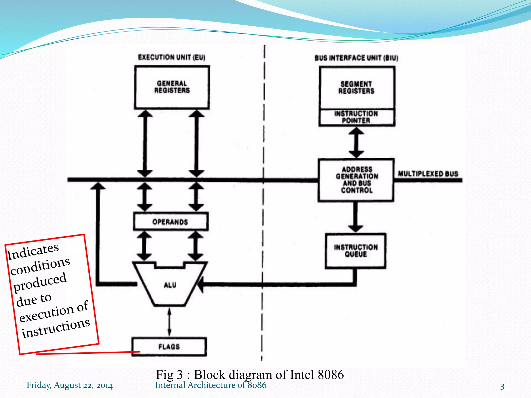
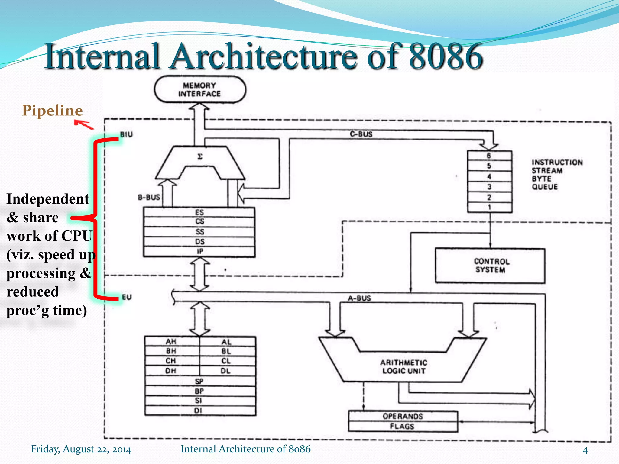
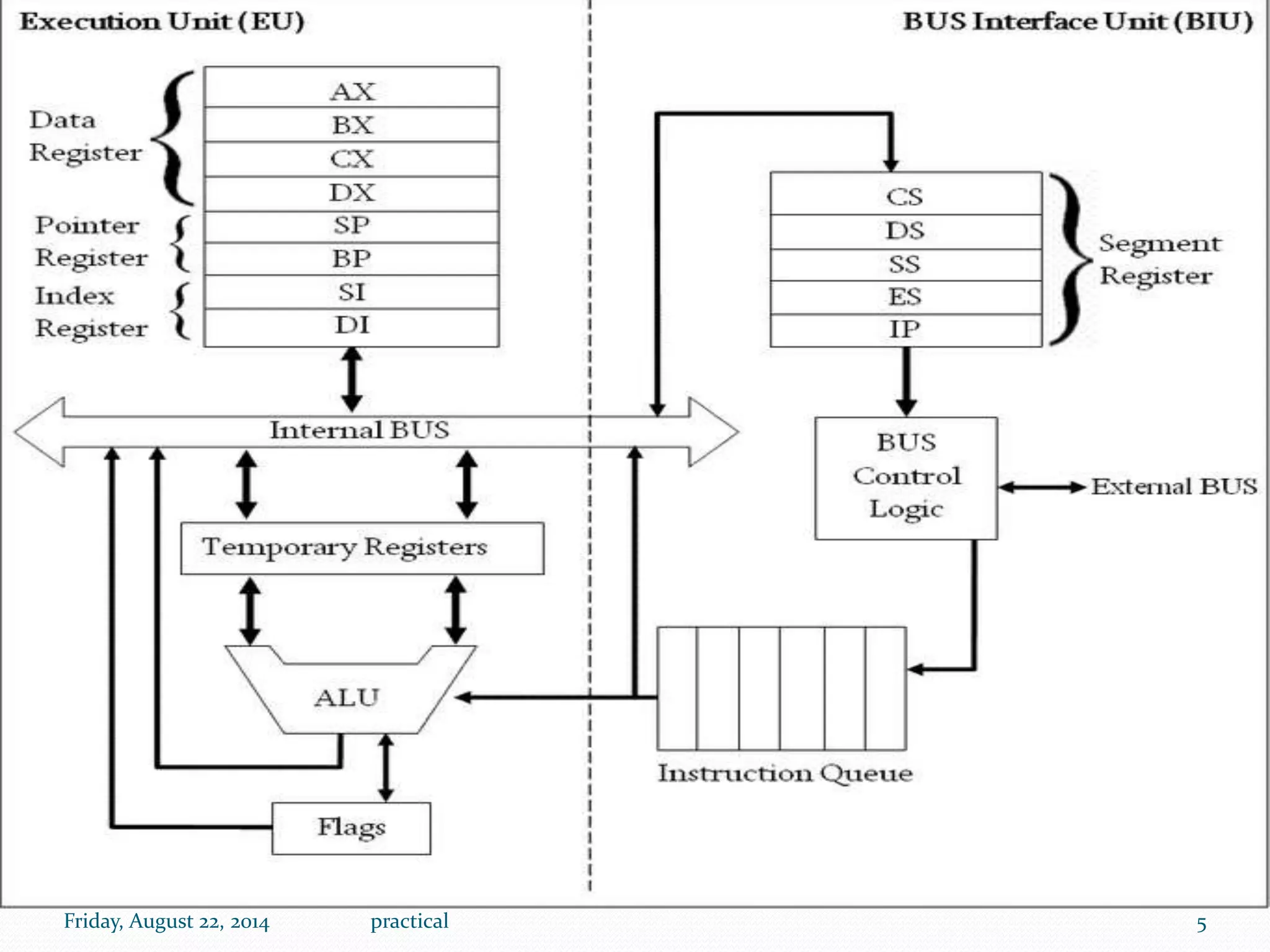
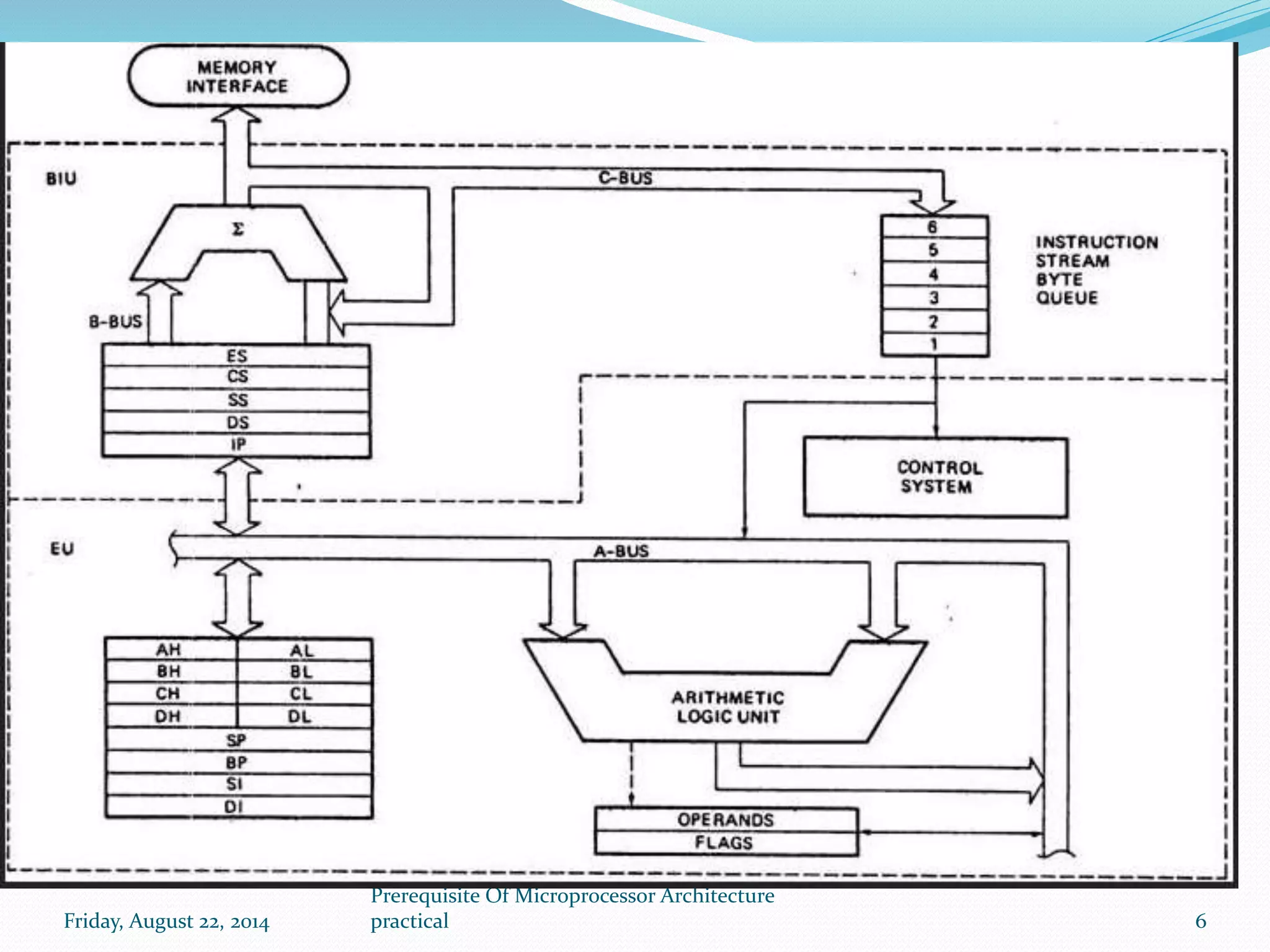
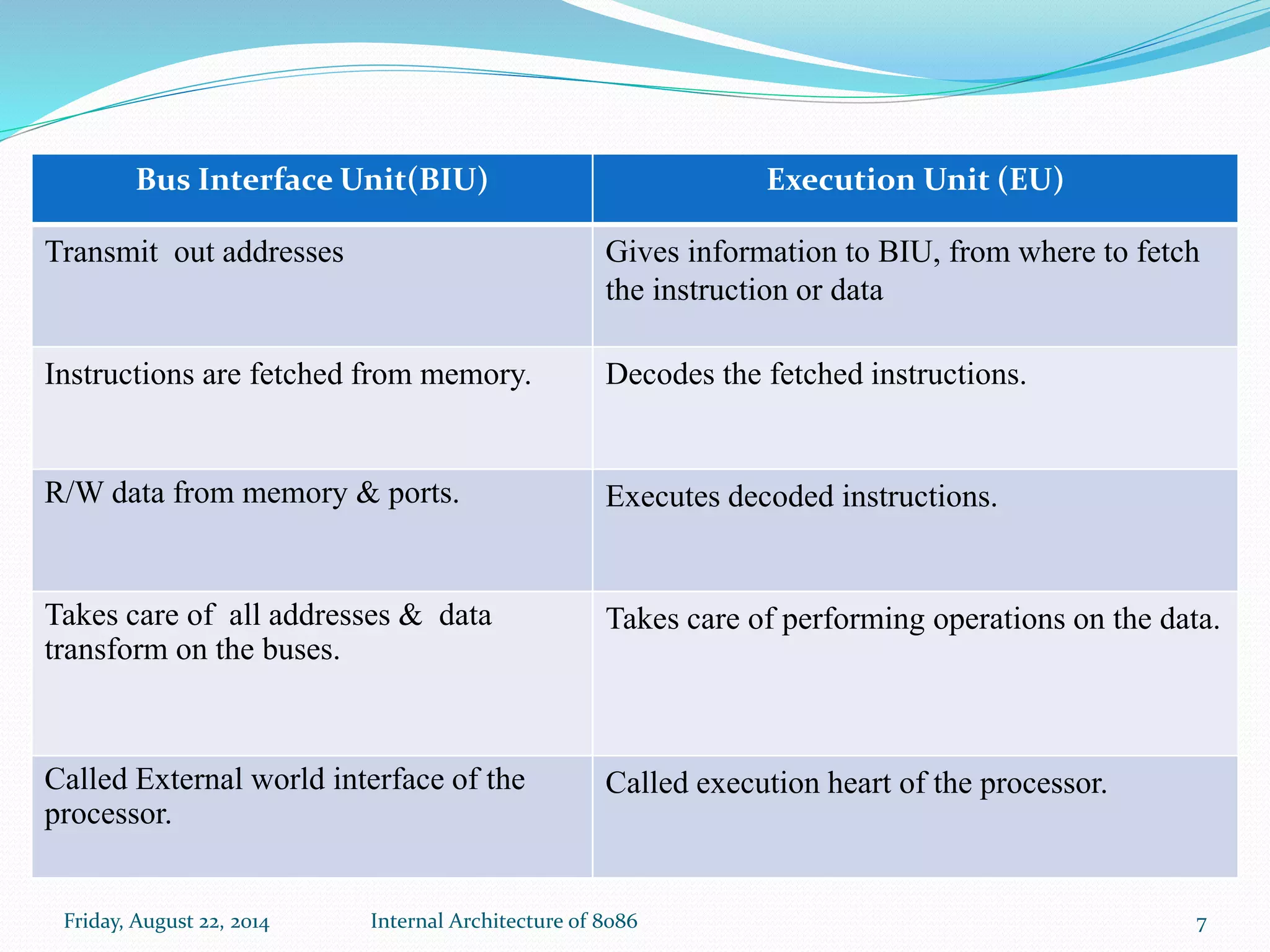
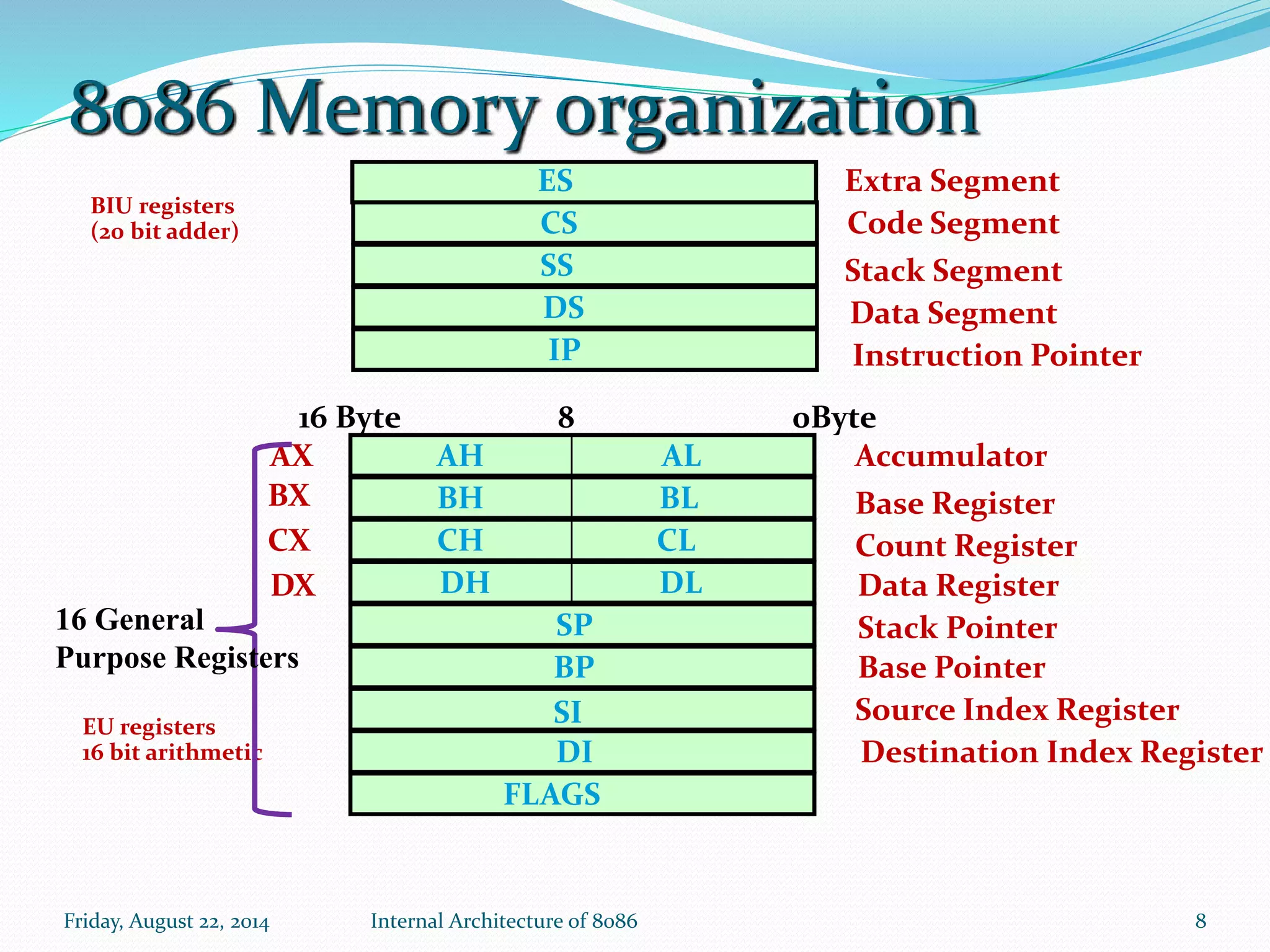
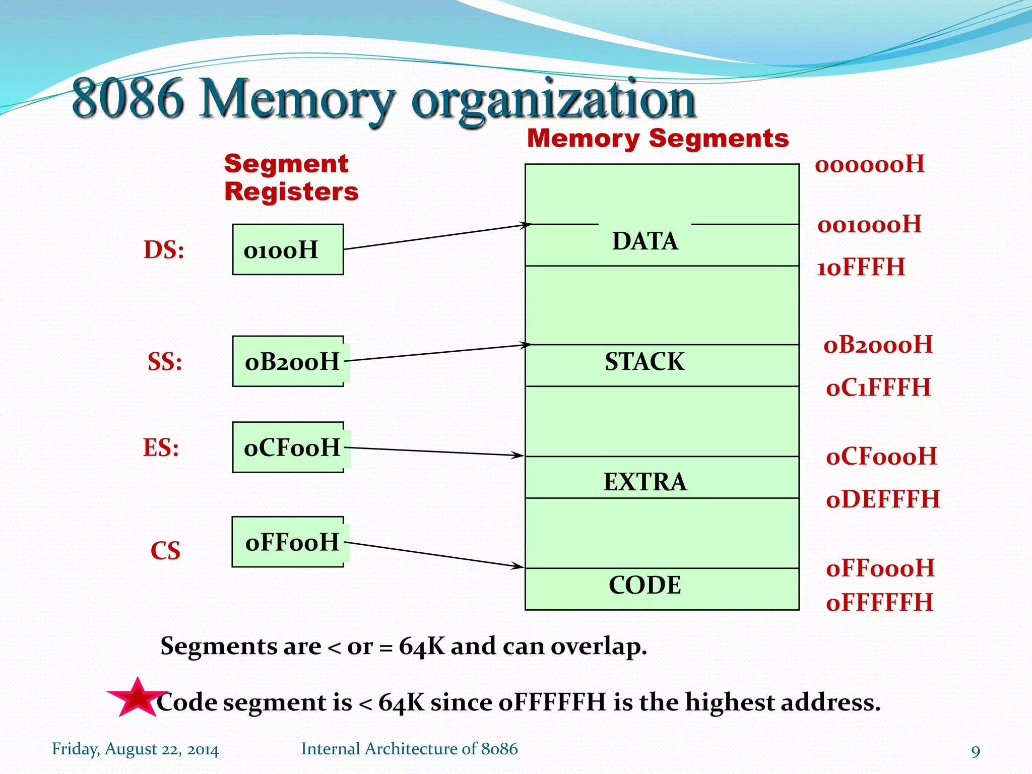
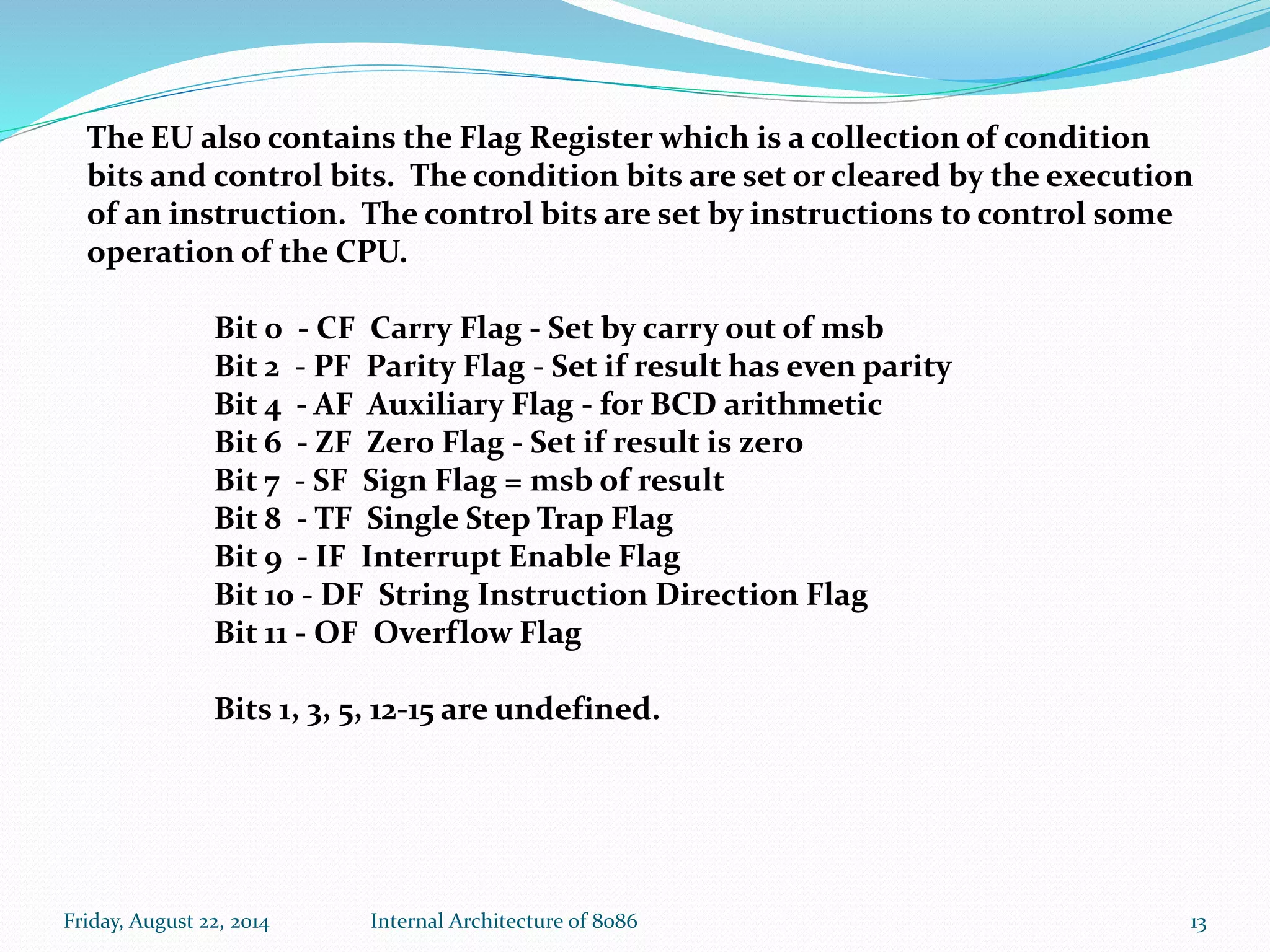
Agenda: Friday, August 22, 2014 Internal Architecture of 8086 1 Microprocessor Vs Microcontroller  Block diagram of 8086 Internal Architecture of 8086 Memory Organization
Friday, August 22, 2014 Internal Architecture of 8086 2 Microprocessor Microcontroller CPU is stand alone, RAM,ROM, I/O & timer are separate. CPU, RAM,ROM, I/O & timer all are on single chip. Designer can decide amount of RAM,ROM, & I/O ports. Fixed amount of on-chip RAM,ROM, & I/O ports. High processing power Low processing power High power consumption Low power consumption Typically 32/64 bit 8/16 bit General purpose Single purpose(control oriented) Less reliable Highly reliable Eg.- 8086,8085 8051
Fig 3 : Block diagram of Intel 8086 Friday, August 22, 2014 3Internal Architecture of 8086
Internal Architecture of 8086 Friday, August 22, 2014 4Internal Architecture of 8086 Independent & share work of CPU (viz. speed up processing & reduced proc’g time) Pipeline
Friday, August 22, 2014 Prerequisite Of Microprocessor Architecture practical 5
Friday, August 22, 2014 6 Prerequisite Of Microprocessor Architecture practical
Friday, August 22, 2014 Internal Architecture of 8086 7 Bus Interface Unit(BIU) Execution Unit (EU) Transmit out addresses Gives information to BIU, from where to fetch the instruction or data Instructions are fetched from memory. Decodes the fetched instructions. R/W data from memory & ports. Executes decoded instructions. Takes care of all addresses & data transform on the buses. Takes care of performing operations on the data. Called External world interface of the processor. Called execution heart of the processor.
Friday, August 22, 2014 Internal Architecture of 8086 8 8086 Memory organization ES CS SS DS IP AH BH CH DH AL BL CL DL SP BP SI DI FLAGS AX BX CX DX Extra Segment Code Segment Stack Segment Data Segment Instruction Pointer Accumulator Base Register Count Register Data Register Stack Pointer Base Pointer Source Index Register Destination Index Register BIU registers (20 bit adder) EU registers 16 bit arithmetic 16 General Purpose Registers 16 Byte 8 0Byte
Friday, August 22, 2014 Internal Architecture of 8086 9 8086 Memory organization CODE DATA STACK EXTRA 0100H 0B200H 0CF00H 0FF00H DS: SS: ES: CS 001000H 0B2000H 0CF000H 0FF000H 10FFFH 0C1FFFH 0DEFFFH 0FFFFFH 000000HSegment Registers Memory Segments Segments are < or = 64K and can overlap. Code segment is < 64K since 0FFFFFH is the highest address.
Friday, August 22, 2014 Internal Architecture of 8086 10 Memory Segmentation additional data segment used by some instructions to hold destination data. Holds programs and Procedures(CODE) used By the microprocessor. defines the area of memory used for the stack. data used by a program
Friday, August 22, 2014 Internal Architecture of 8086 11  Allow the memory capacity to be 1Mb even though the addresses associated with the individual instructions are only 16 bits wide.  Facilitate the use of separate memory areas for the program, its data and the stack.  Multitasking becomes easy. Advantages Of Memory Segmentation
 Allow the memory capacity to be 1Mb even though the addresses associated with the individual instructions are only 16 bits wide.  Facilitate the use of separate memory areas for the program, its data and the stack.  Multitasking becomes easy. Advantages of memory segmentation
Friday, August 22, 2014 Internal Architecture of 8086 13 The EU also contains the Flag Register which is a collection of condition bits and control bits. The condition bits are set or cleared by the execution of an instruction. The control bits are set by instructions to control some operation of the CPU. Bit 0 - CF Carry Flag - Set by carry out of msb Bit 2 - PF Parity Flag - Set if result has even parity Bit 4 - AF Auxiliary Flag - for BCD arithmetic Bit 6 - ZF Zero Flag - Set if result is zero Bit 7 - SF Sign Flag = msb of result Bit 8 - TF Single Step Trap Flag Bit 9 - IF Interrupt Enable Flag Bit 10 - DF String Instruction Direction Flag Bit 11 - OF Overflow Flag Bits 1, 3, 5, 12-15 are undefined.
Friday, August 22, 2014 Internal Architecture of 8086 14
Friday, August 22, 2014 Internal Architecture of 8086 15

Microprocessor vs. microcontroller

  • 1.
    Agenda: Friday, August 22,2014 Internal Architecture of 8086 1 Microprocessor Vs Microcontroller  Block diagram of 8086 Internal Architecture of 8086 Memory Organization
  • 2.
    Friday, August 22,2014 Internal Architecture of 8086 2 Microprocessor Microcontroller CPU is stand alone, RAM,ROM, I/O & timer are separate. CPU, RAM,ROM, I/O & timer all are on single chip. Designer can decide amount of RAM,ROM, & I/O ports. Fixed amount of on-chip RAM,ROM, & I/O ports. High processing power Low processing power High power consumption Low power consumption Typically 32/64 bit 8/16 bit General purpose Single purpose(control oriented) Less reliable Highly reliable Eg.- 8086,8085 8051
  • 3.
    Fig 3 :Block diagram of Intel 8086 Friday, August 22, 2014 3Internal Architecture of 8086
  • 4.
    Internal Architecture of8086 Friday, August 22, 2014 4Internal Architecture of 8086 Independent & share work of CPU (viz. speed up processing & reduced proc’g time) Pipeline
  • 5.
    Friday, August 22,2014 Prerequisite Of Microprocessor Architecture practical 5
  • 6.
    Friday, August 22,2014 6 Prerequisite Of Microprocessor Architecture practical
  • 7.
    Friday, August 22,2014 Internal Architecture of 8086 7 Bus Interface Unit(BIU) Execution Unit (EU) Transmit out addresses Gives information to BIU, from where to fetch the instruction or data Instructions are fetched from memory. Decodes the fetched instructions. R/W data from memory & ports. Executes decoded instructions. Takes care of all addresses & data transform on the buses. Takes care of performing operations on the data. Called External world interface of the processor. Called execution heart of the processor.
  • 8.
    Friday, August 22,2014 Internal Architecture of 8086 8 8086 Memory organization ES CS SS DS IP AH BH CH DH AL BL CL DL SP BP SI DI FLAGS AX BX CX DX Extra Segment Code Segment Stack Segment Data Segment Instruction Pointer Accumulator Base Register Count Register Data Register Stack Pointer Base Pointer Source Index Register Destination Index Register BIU registers (20 bit adder) EU registers 16 bit arithmetic 16 General Purpose Registers 16 Byte 8 0Byte
  • 9.
    Friday, August 22,2014 Internal Architecture of 8086 9 8086 Memory organization CODE DATA STACK EXTRA 0100H 0B200H 0CF00H 0FF00H DS: SS: ES: CS 001000H 0B2000H 0CF000H 0FF000H 10FFFH 0C1FFFH 0DEFFFH 0FFFFFH 000000HSegment Registers Memory Segments Segments are < or = 64K and can overlap. Code segment is < 64K since 0FFFFFH is the highest address.
  • 10.
    Friday, August 22,2014 Internal Architecture of 8086 10 Memory Segmentation additional data segment used by some instructions to hold destination data. Holds programs and Procedures(CODE) used By the microprocessor. defines the area of memory used for the stack. data used by a program
  • 11.
    Friday, August 22,2014 Internal Architecture of 8086 11  Allow the memory capacity to be 1Mb even though the addresses associated with the individual instructions are only 16 bits wide.  Facilitate the use of separate memory areas for the program, its data and the stack.  Multitasking becomes easy. Advantages Of Memory Segmentation
  • 12.
     Allow thememory capacity to be 1Mb even though the addresses associated with the individual instructions are only 16 bits wide.  Facilitate the use of separate memory areas for the program, its data and the stack.  Multitasking becomes easy. Advantages of memory segmentation
  • 13.
    Friday, August 22,2014 Internal Architecture of 8086 13 The EU also contains the Flag Register which is a collection of condition bits and control bits. The condition bits are set or cleared by the execution of an instruction. The control bits are set by instructions to control some operation of the CPU. Bit 0 - CF Carry Flag - Set by carry out of msb Bit 2 - PF Parity Flag - Set if result has even parity Bit 4 - AF Auxiliary Flag - for BCD arithmetic Bit 6 - ZF Zero Flag - Set if result is zero Bit 7 - SF Sign Flag = msb of result Bit 8 - TF Single Step Trap Flag Bit 9 - IF Interrupt Enable Flag Bit 10 - DF String Instruction Direction Flag Bit 11 - OF Overflow Flag Bits 1, 3, 5, 12-15 are undefined.
  • 14.
    Friday, August 22,2014 Internal Architecture of 8086 14
  • 15.
    Friday, August 22,2014 Internal Architecture of 8086 15