The document outlines a project on constructing a radar system using Arduino and processing software, detailing components such as the Arduino Uno board, ultrasonic sensor, and servo motor. It explains the project’s objective to detect obstacles and enhance safety through accurate distance measurement from 2 to 3 meters. The future scope includes advancements in radar technology, specifically the development of LiDAR for improved object detection.
Department of ComputerScience Engineering Guided by Mr.Abhishek Singh Assistant Professor EE Department Submitted by Mohit Jain Rashi Jain Mansi Sharma Yash Khandelwal Priyanshu Kansal Coordinated by Mr. Amit Kumar Singh H.O.D. Department of Electrical Engineering
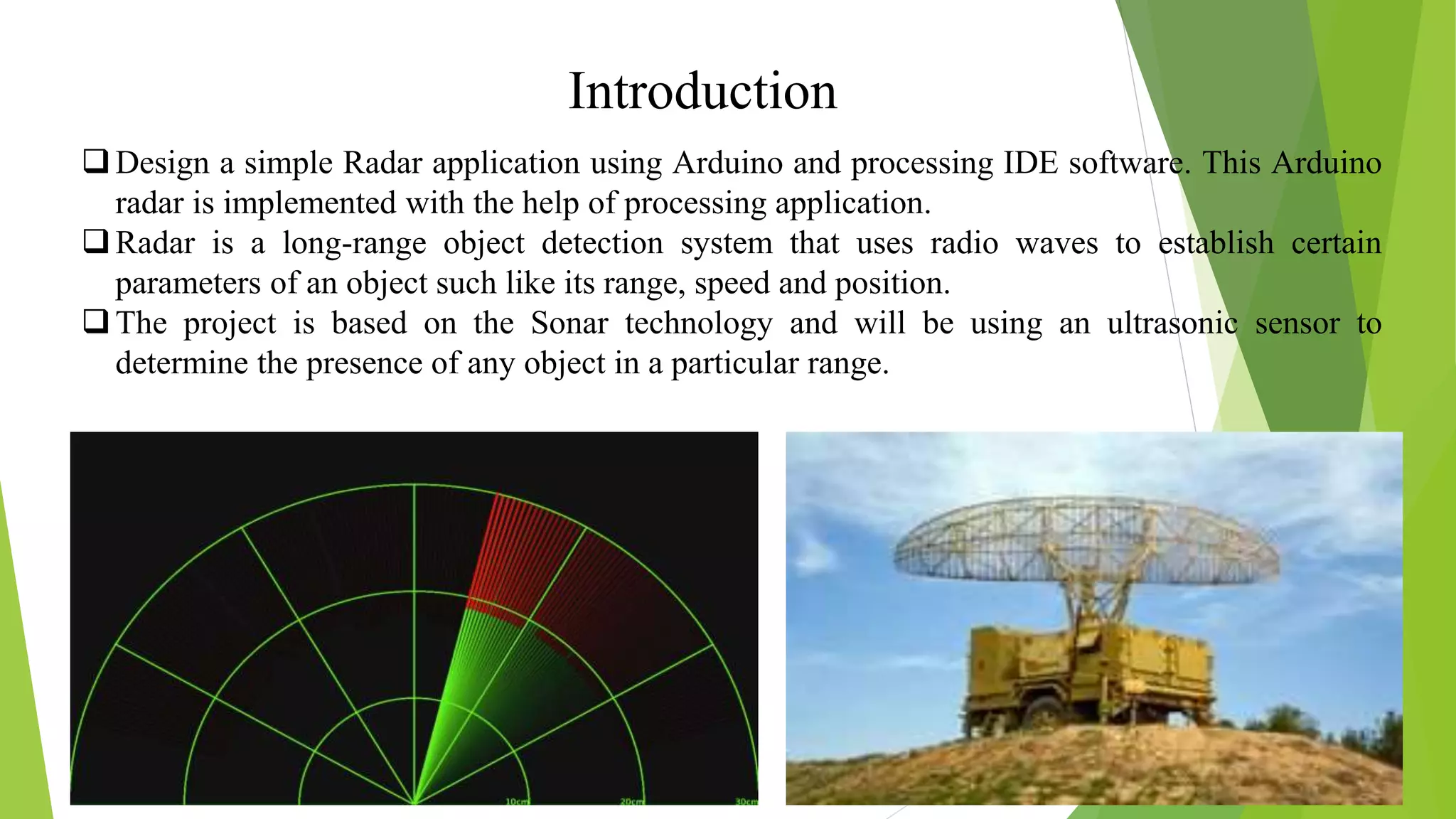
Introduction Design a simpleRadar application using Arduino and processing IDE software. This Arduino radar is implemented with the help of processing application. Radar is a long-range object detection system that uses radio waves to establish certain parameters of an object such like its range, speed and position. The project is based on the Sonar technology and will be using an ultrasonic sensor to determine the presence of any object in a particular range.
5.
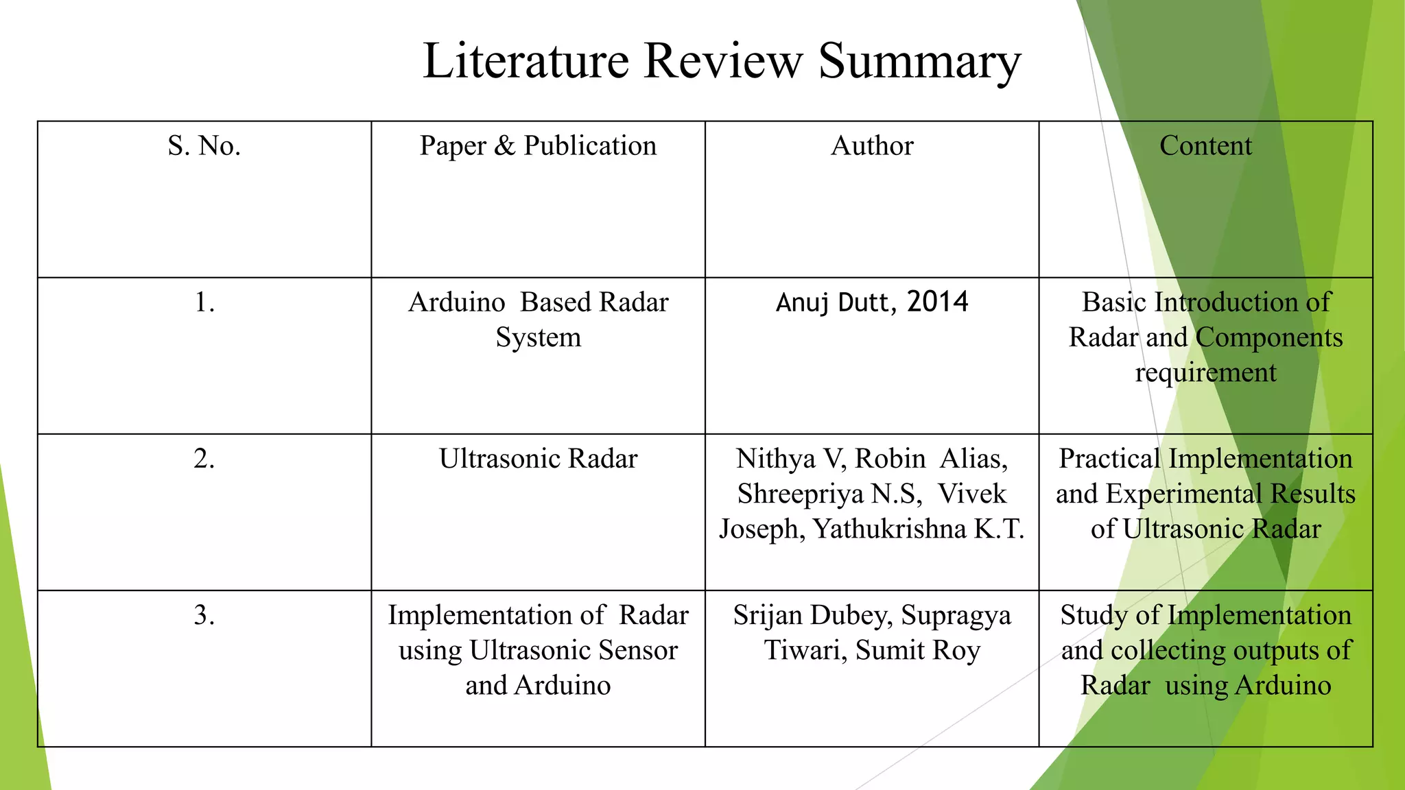
S. No. Paper& Publication Author Content 1. Arduino Based Radar System Anuj Dutt, 2014 Basic Introduction of Radar and Components requirement 2. Ultrasonic Radar Nithya V, Robin Alias, Shreepriya N.S, Vivek Joseph, Yathukrishna K.T. Practical Implementation and Experimental Results of Ultrasonic Radar 3. Implementation of Radar using Ultrasonic Sensor and Arduino Srijan Dubey, Supragya Tiwari, Sumit Roy Study of Implementation and collecting outputs of Radar using Arduino Literature Review Summary
6.
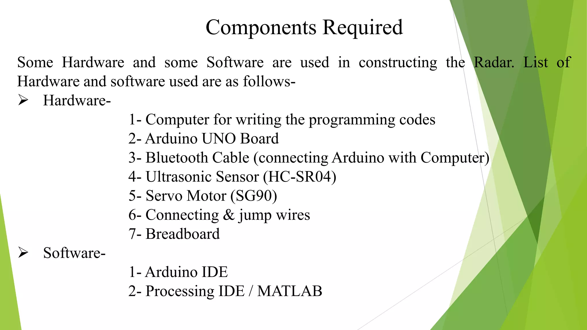
Components Required Some Hardwareand some Software are used in constructing the Radar. List of Hardware and software used are as follows- Hardware- 1- Computer for writing the programming codes 2- Arduino UNO Board 3- Bluetooth Cable (connecting Arduino with Computer) 4- Ultrasonic Sensor (HC-SR04) 5- Servo Motor (SG90) 6- Connecting & jump wires 7- Breadboard Software- 1- Arduino IDE 2- Processing IDE / MATLAB
7.
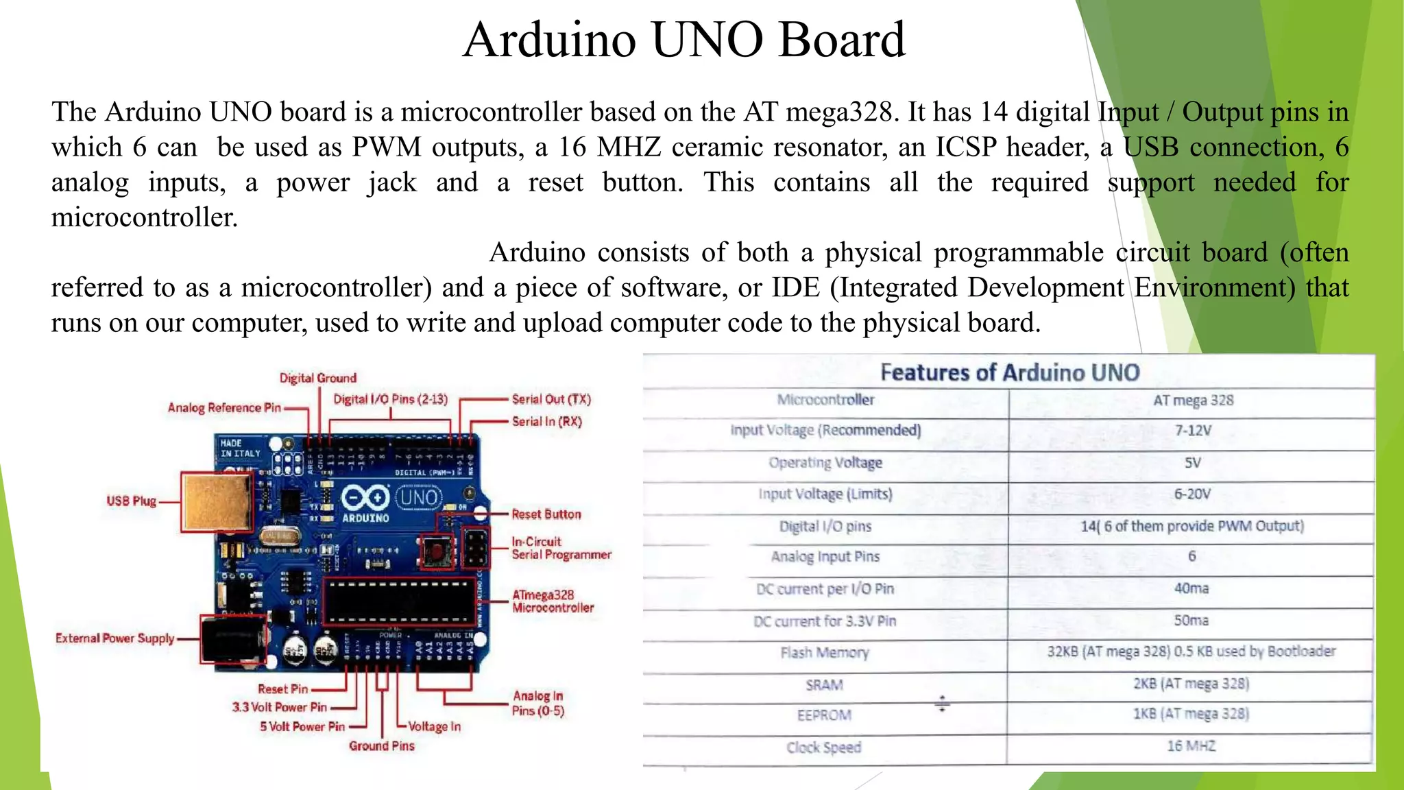
Arduino UNO Board TheArduino UNO board is a microcontroller based on the AT mega328. It has 14 digital Input / Output pins in which 6 can be used as PWM outputs, a 16 MHZ ceramic resonator, an ICSP header, a USB connection, 6 analog inputs, a power jack and a reset button. This contains all the required support needed for microcontroller. Arduino consists of both a physical programmable circuit board (often referred to as a microcontroller) and a piece of software, or IDE (Integrated Development Environment) that runs on our computer, used to write and upload computer code to the physical board.
8.
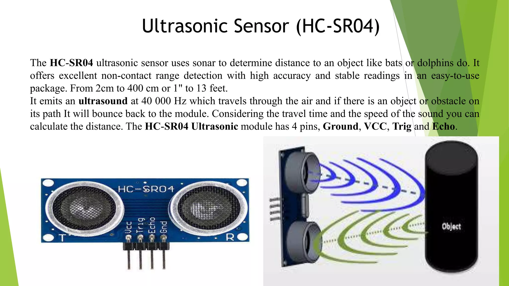
Ultrasonic Sensor (HC-SR04) TheHC-SR04 ultrasonic sensor uses sonar to determine distance to an object like bats or dolphins do. It offers excellent non-contact range detection with high accuracy and stable readings in an easy-to-use package. From 2cm to 400 cm or 1" to 13 feet. It emits an ultrasound at 40 000 Hz which travels through the air and if there is an object or obstacle on its path It will bounce back to the module. Considering the travel time and the speed of the sound you can calculate the distance. The HC-SR04 Ultrasonic module has 4 pins, Ground, VCC, Trig and Echo.
9.
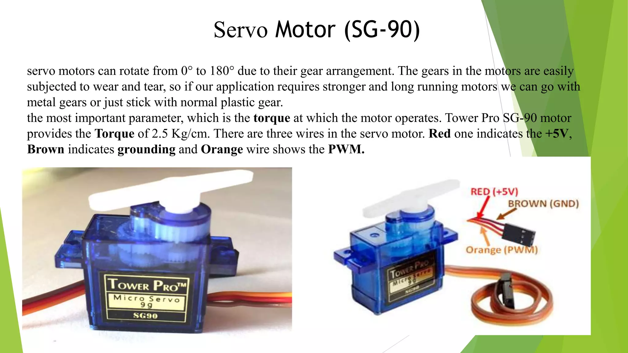
Servo Motor (SG-90) servomotors can rotate from 0° to 180° due to their gear arrangement. The gears in the motors are easily subjected to wear and tear, so if our application requires stronger and long running motors we can go with metal gears or just stick with normal plastic gear. the most important parameter, which is the torque at which the motor operates. Tower Pro SG-90 motor provides the Torque of 2.5 Kg/cm. There are three wires in the servo motor. Red one indicates the +5V, Brown indicates grounding and Orange wire shows the PWM.
10.
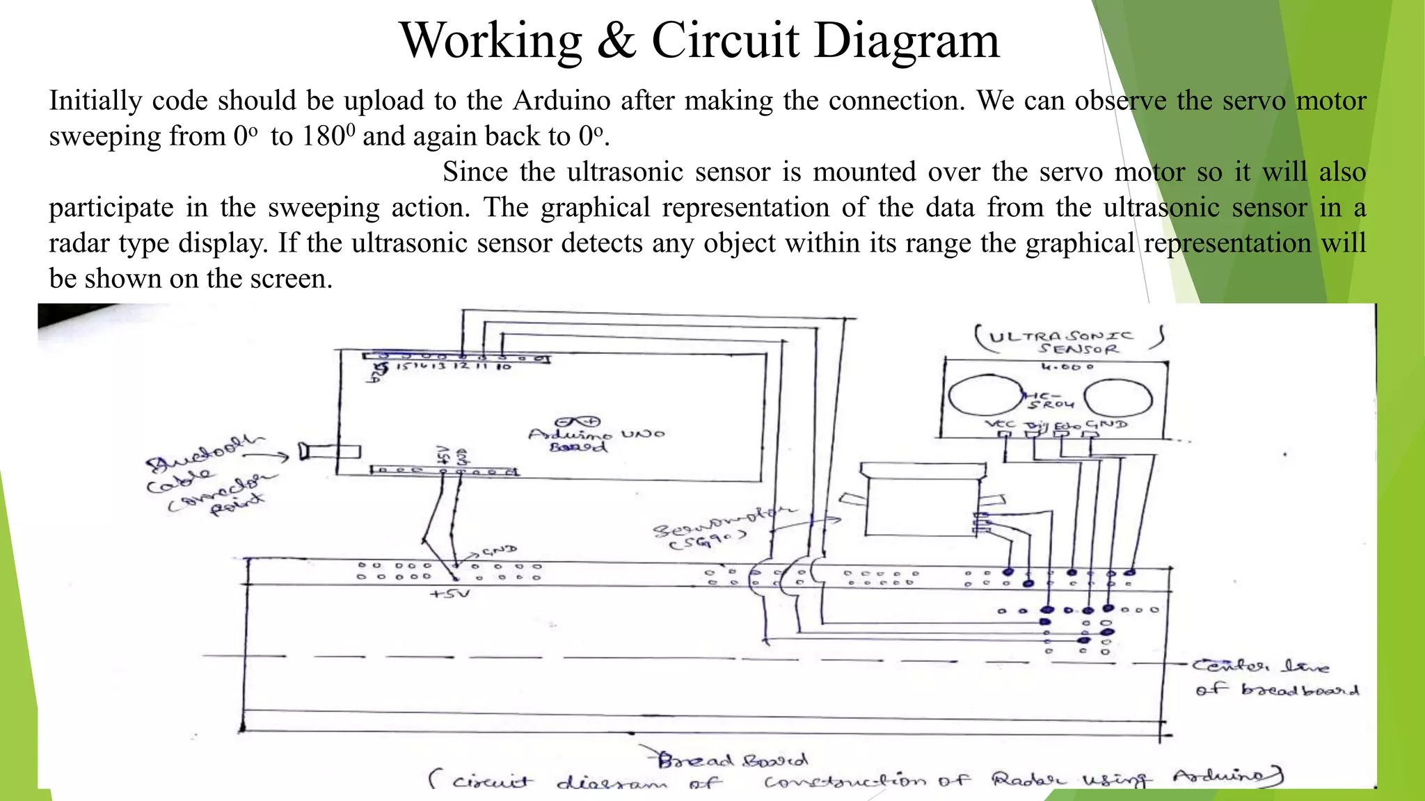
Working & CircuitDiagram Initially code should be upload to the Arduino after making the connection. We can observe the servo motor sweeping from 0o to 1800 and again back to 0o. Since the ultrasonic sensor is mounted over the servo motor so it will also participate in the sweeping action. The graphical representation of the data from the ultrasonic sensor in a radar type display. If the ultrasonic sensor detects any object within its range the graphical representation will be shown on the screen.
11.
Objective The objective ofthe project is to detect the obstacle using Ultrasonic Sensor, Arduino UNO board and MATLAB or Processing coding as a platform to display the results. To prevent or reduce the accidents and useful for security and protection. Detection of objects come in the range of 2 to 3 meters and give signal to the observer about the object.
12.
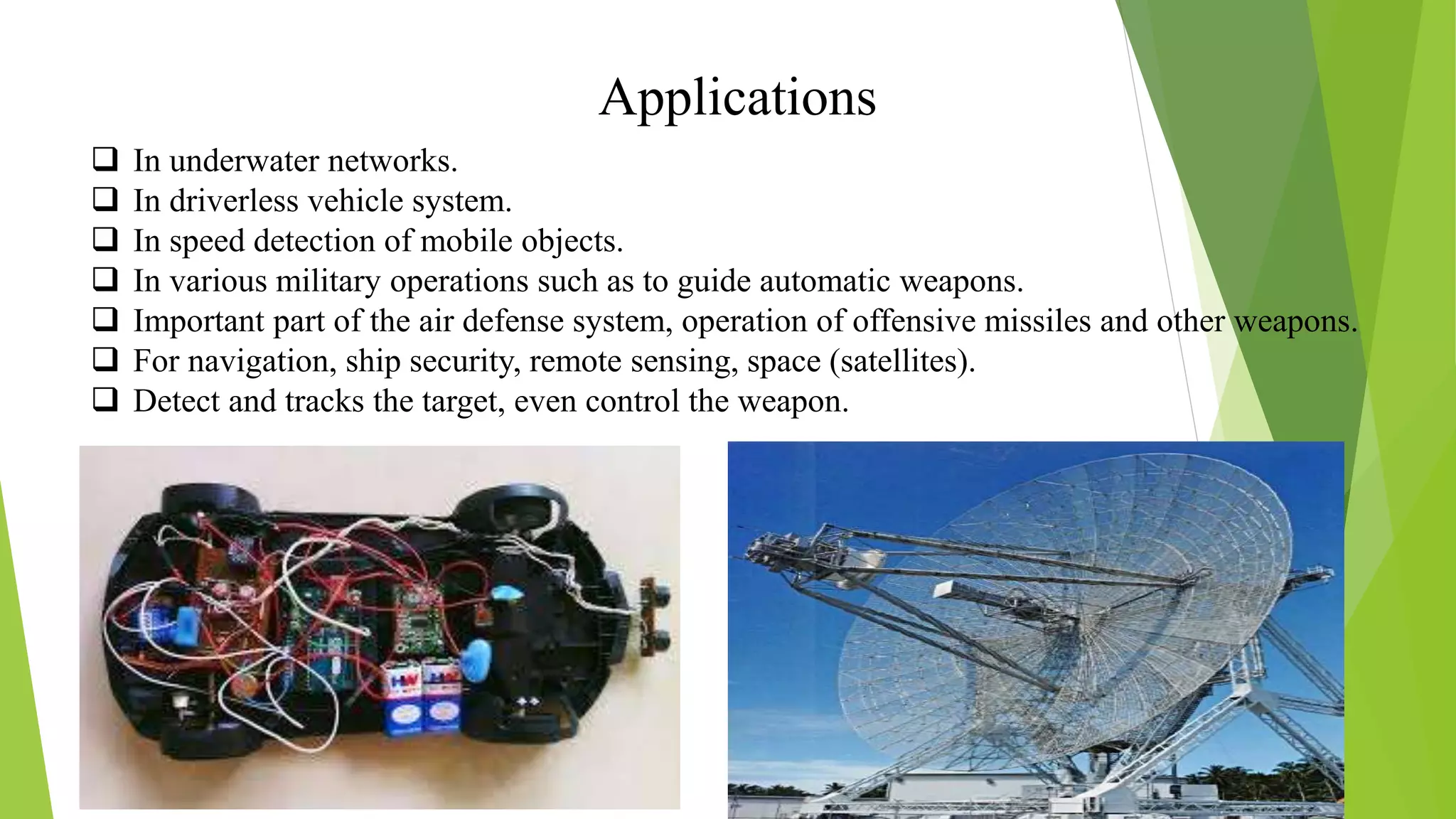
Applications In underwaternetworks. In driverless vehicle system. In speed detection of mobile objects. In various military operations such as to guide automatic weapons. Important part of the air defense system, operation of offensive missiles and other weapons. For navigation, ship security, remote sensing, space (satellites). Detect and tracks the target, even control the weapon.
13.
Conclusion & ExpectedOutcome Radar is used to find velocity, long-range and position of the object. Advantage of RADAR is that it provide superior penetration capability through any type of weather condition. Range of the object detection for the current project is between 2 to 3 meters. To increase the range of object detection, Radar can be made more improved which is known as “Lidar”. Lidar is advanced type of Radar which uses visible light from laser.
14.
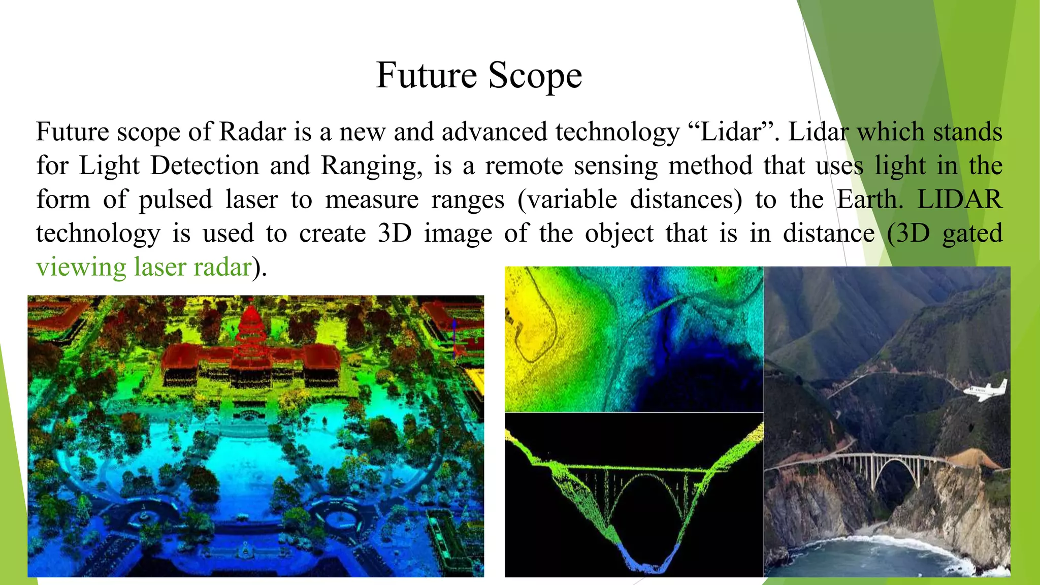
Future Scope Future scopeof Radar is a new and advanced technology “Lidar”. Lidar which stands for Light Detection and Ranging, is a remote sensing method that uses light in the form of pulsed laser to measure ranges (variable distances) to the Earth. LIDAR technology is used to create 3D image of the object that is in distance (3D gated viewing laser radar).
![References https://howtomechatronics.com/projects/arduino-radar-project. https://electronicsforu.com/videos-slideshows/videos/constructing-radar-Arduino. Http://radartutorial.en (intro, Principle of operation) Http://microcontrollerslab.com/servo-motor-control-and-interfacing-with-Arduino. Translation Bureau (2013). "Radar definition". Public Works and Government Services Canada. Retrieved March 18, 2017. McGraw-Hill dictionary of scientific and technical terms / Daniel N. Lapedes, editor in chief. Lapedes, Daniel N. New York ; Montreal : McGraw-Hill, 1976. [xv], 1634, A26 p. “Crashless car: Making driving safer” https://www.scientificamerican.com/article/crash less-cars by Steven Asley Retrieved March 19, 2017.](https://image.slidesharecdn.com/mresentation-200208161155/75/Radar-Using-Arduino-15-2048.jpg)