Downloaded 14 times
![International Research Journal of Engineering and Technology (IRJET) e-ISSN: 2395 -0056 p-ISSN: 2395-0072Volume: 04 Issue: 10 | Oct -2017 www.irjet.net through servo mechanism. Servo Motor is a rotary actuator or linear actuator that allows for precise control of angular or linear position, velocity and acceleration. Servos are controlled by sending an electrical pulse of variable width, or pulse width modulation [PWM] through the control wire. Servo motors have three wires: power, ground, and signal. If motor is used is DC powered then it is called DC servo motor, and if it is AC powered motor then it is called AC servo motor. The position of servo motor is decided by electrical pulse and its circuitry is placed beside the motor. Fig -3: Servo Motor 2.1.4 ZIGBEE ZigBee is a new wireless technology guided by IEEE 802.15.4. It is currently operates 2.4GHZ in worldwide at a maximum data rate up to 250kbps. One of the major advantages is provide noise free for communication. There are three different devices: (1) ZigBee coordinator node, (2) The full function devices FFD, (3) The reduced function device RFD. ZigBee provides the ability to run for years on inexpensive batteries for a host of monitoring and control applications. The ZigBee network layer ensures that networks remain operable in the conditions of a constantly changing quality between communication nodes. Fig -4: ZigBee Table -2: ZigBee specifications Power supply Years Distance 50-1600m Complicity Simple Transmission Speed 256kbps Frequency Range 915MHZ (US), 2.4GHZNetwork Nodes 65535 DC Current for 3.3V Pin 50 mA Power Output 1-100mW Frequency Hopping Direct Spread SpectrumSecurity 128bit 3. FLOW CHART Fig -5: Flowchart of Hardware System First, we set the baud rate 9600 to communicate with the MATLAB. Here we are mounting ultrasonic module on the servo motor which rotate 180° from clockwise to anti- clockwise direction for this we set. PWM for servo motor. After than choosing the timer we are sending 10µS pulse width on ultrasonic TX pin. Now RX echo pulse width calculates by Arduino Uno microcontroller. After than the real time distance passing for MATLAB terminal at 9600 baud rate. This distance display on MATLAB through graphical geo. © 2017, IRJET | Impact Factor value: 5.181 | ISO 9001:2008Certified Journal | Page 337](https://image.slidesharecdn.com/irjet-v4i1059-171124100341/75/Short-Range-Radar-System-using-Arduino-Uno-3-2048.jpg)
![International Research Journal of Engineering and Technology (IRJET) e-ISSN: 2395 -0056 p-ISSN: 2395-0072Volume: 04 Issue: 10 | Oct -2017 www.irjet.net 4. HARDWARE RESULT Fig -6: Result of Hardware 5. CONCLUSION We have represented a project on Ultrasonic RADAR for security system for human or object interference in a short range. The system has been successfully implemented and the aim is achieved without any deviation. There is a lot of future scope of this project because of its security capacity. It can be used in many applications. This project can also be developed or modified according to the rising needs and demand. REFERENCES [1] Gangaram Bhor, Pratik Bhandari, Rahul Ghodekar, Sushant Deshmukh,” Mini Radar”, e-ISSN: 2330- 8163, March-2016 [2] Yusuf Abdullahi Badamasi, “The Working Principle Of An Arduino”, 978-1-4799-4106-3/14, © 2014 IEEE [3] http://radartutorial.en (intro, principle of operation) [4] http://microcontrollerslab.com/servo-motor-control- and-interfacing-with-arduino [5] https://en.wikipedia.org [6] http://robotforpro.blogspot.in (sensor) [7] Nikhil Kawade, Shaguftah Mulla, Gayatri Mahale, Rohit Mahapure,’ Intrusion Detection and Identification in Water Distribution Network”, Vol:4, Issue: 4, April: 2017 [8] https://www.jlab.org/ir/MITSeries/V1-1.pdf © 2017, IRJET | Impact Factor value: 5.181 | ISO 9001:2008Certified Journal | Page 338](https://image.slidesharecdn.com/irjet-v4i1059-171124100341/75/Short-Range-Radar-System-using-Arduino-Uno-4-2048.jpg)

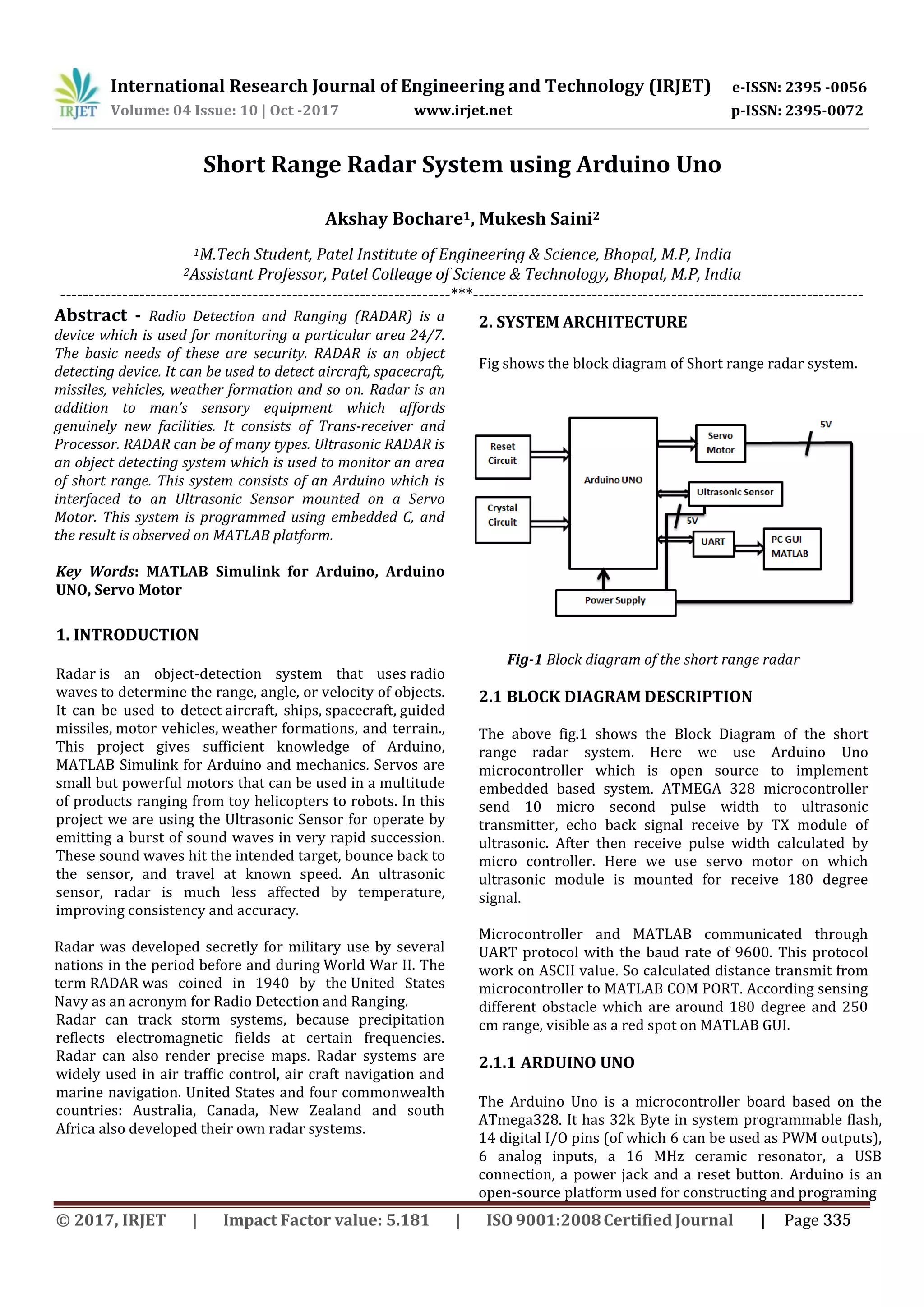
This document describes the design and implementation of a short range radar system using an Arduino Uno. The system uses an ultrasonic sensor mounted on a servo motor to detect objects within 180 degrees and up to 250cm. The Arduino transmits pulse signals to the ultrasonic sensor and calculates distance based on the echo return time. Distances are sent to MATLAB via UART communication and displayed graphically. The system is able to continuously monitor and detect obstacles in a short range area.