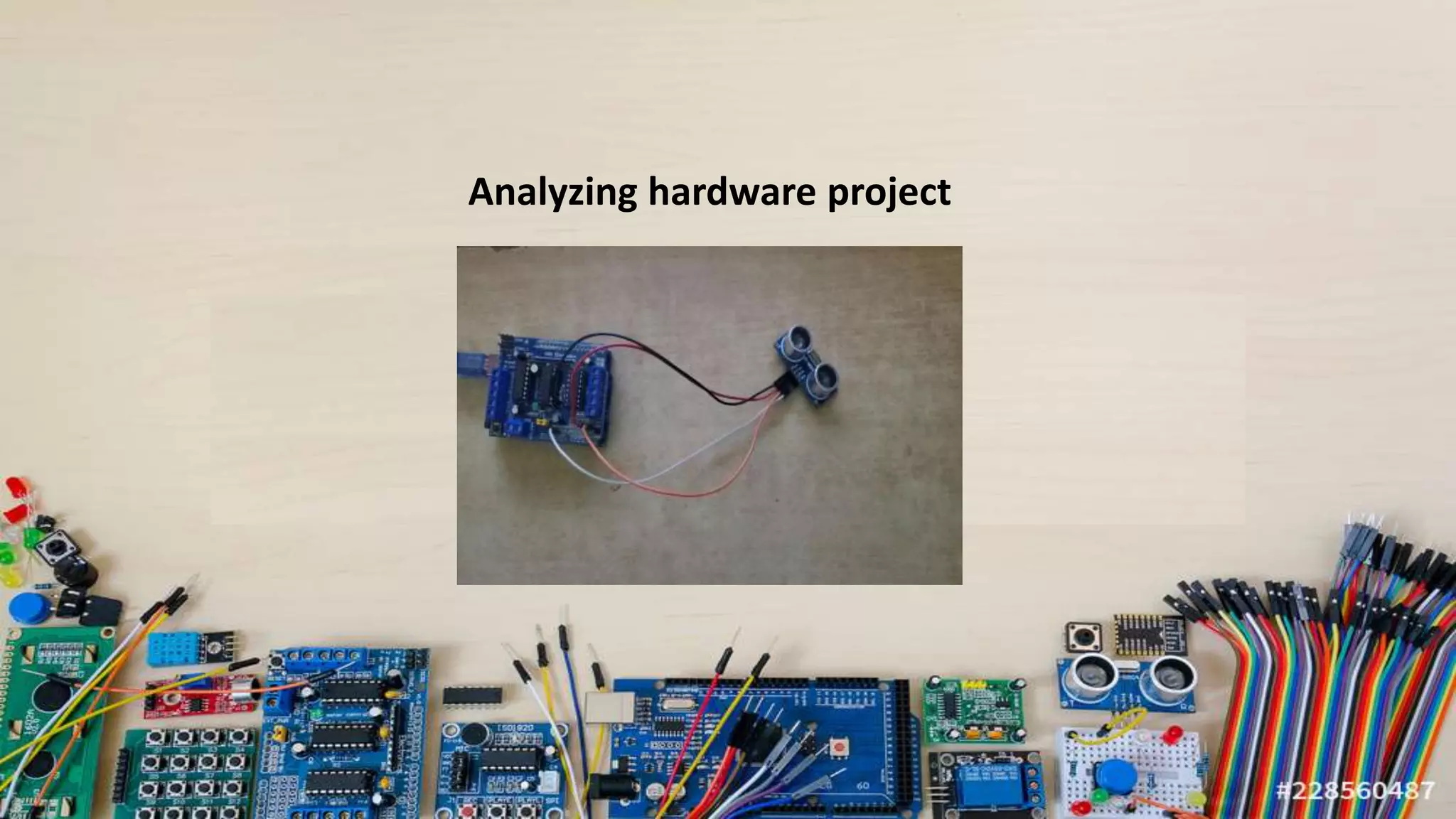
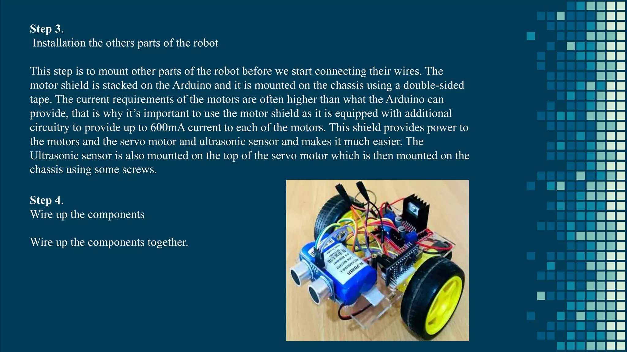
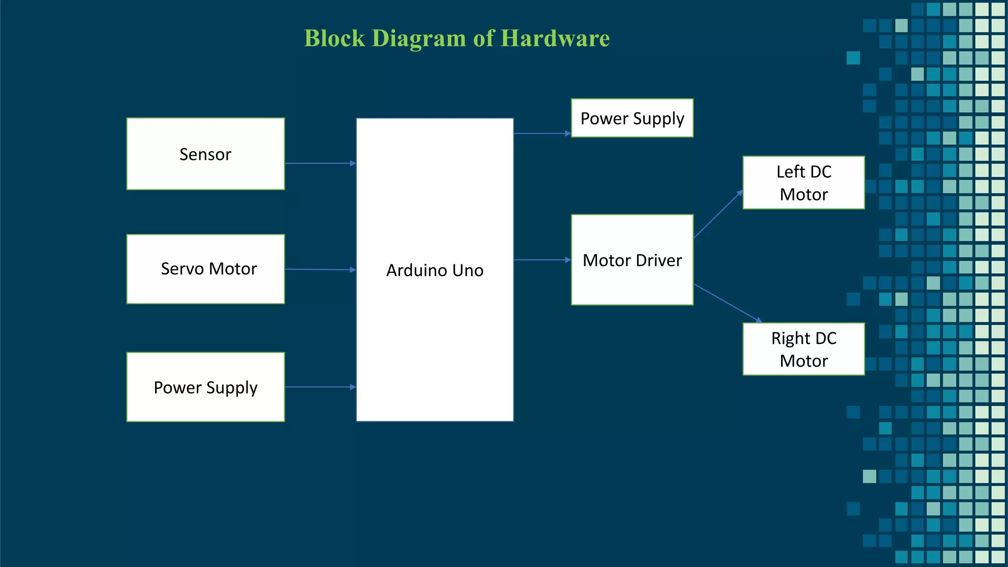
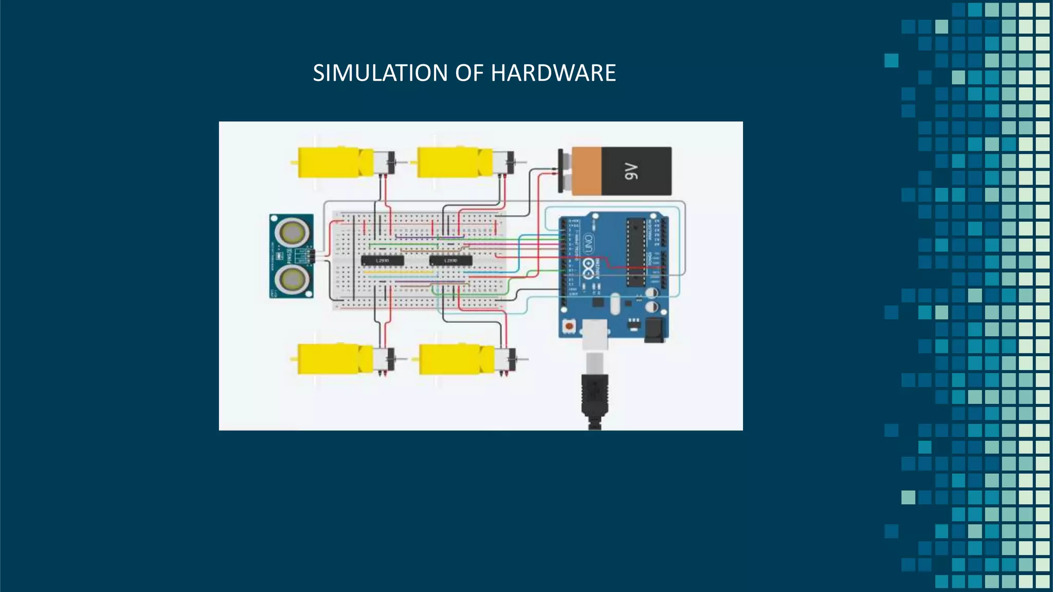
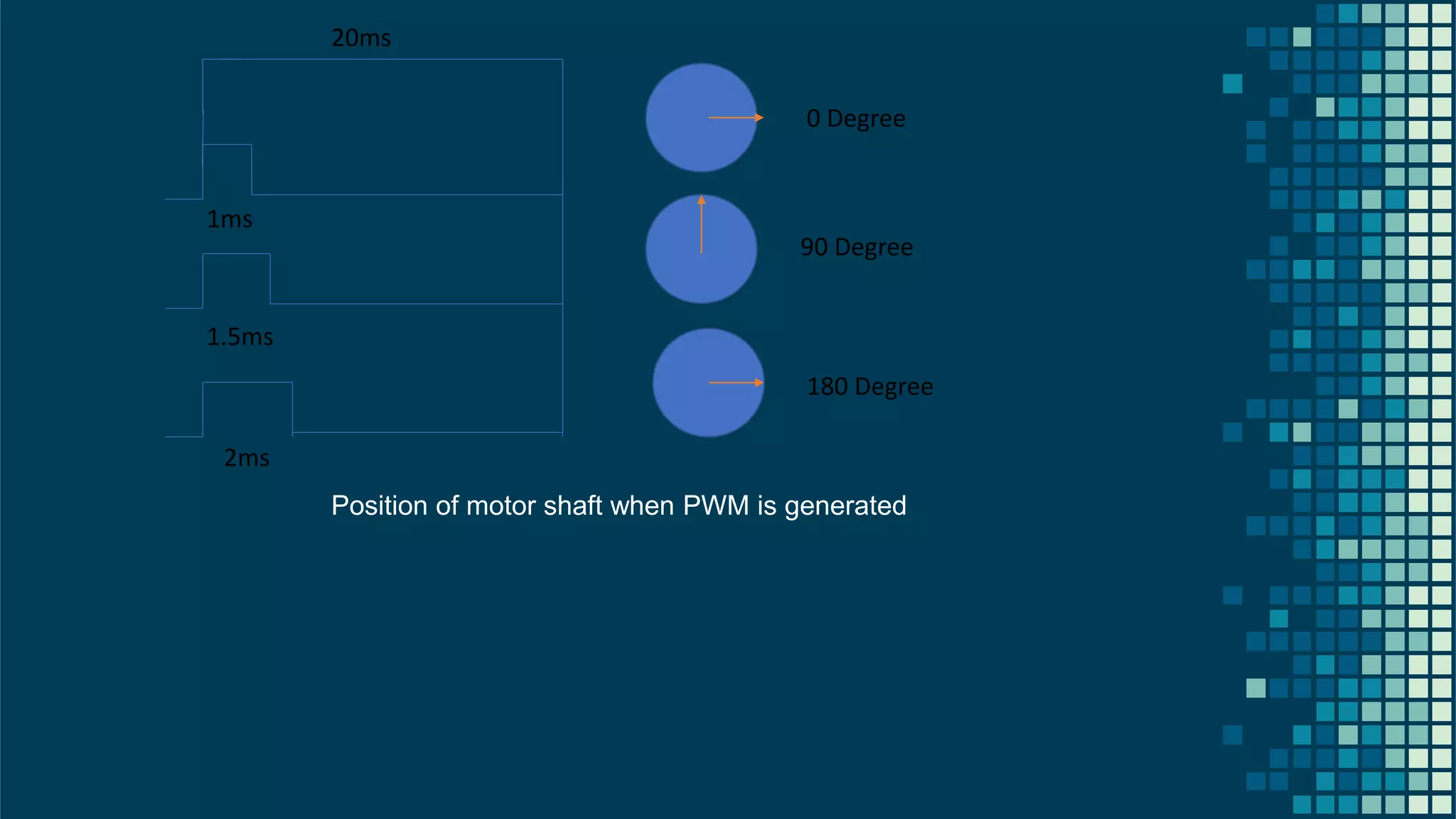
NAL REPORT 1)Jeevan Prakash H A –20BRS1259 (Leader) Ashvant N.-20BEC1292 HE HAS LEFT THE COLLEGE.ALL ARE DONE BY MYSELF
ECE 1006 NANOSCIENCE AND NANOTECHNOLOGY
NANOSCIENCE AND NANOTECHNOLOGY A project report submitted to Dr. ARIVARASI A SCHOOL OF ELECTRONICS ENGINEERING in partial fulfilment of the requirements for the course of ECE 1006 NANOSCIENCE AND NANOTECHNOLOGY In B. Tech School of Computer Science and Engineering Kelambakkam - Vandalur Rd, Rajan Nagar, Chennai, Tamil Nadu 600127
TITLE OF THE PROJECT OBSTACLE-AVOIDING ROBOT BY JEEVAN PRAKASH HA-20BRS1259
BONAFIDE CERTIFICATE Certified that this project report entitled “OBSTACLE-AVOIDING ROBOT ” has Bonafede worker JEEVAN PRAKASH HA 20BRS1259 who carried out the Project work for ECE 1006 NANOSCIENCE AND NANOTECHNOLOGY . Dr. ARIVARASI Associate Professor School of Electronics Engineering, VIT University, Chennai Chennai –600 127.
ACKNOWLEDGEMENT We wish to express our sincere thanks and deep sense of gratitude to our project guide, Dr. ARIVARASI A, Associate Professor, School of Electronics Engineering, for her consistent encouragement and valuable guidance offered to us in a pleasant manner throughout the course of the project work. We are extremely grateful to Dr. JAGADEESH KANNAN R, Dean of School of Computer Science and Engineering, VIT Chennai, for extending the facilities of the School towards our project and for his unstinting support. We express our thanks to our Head of the Department Dr. REKHA D for his support throughout the course of this project. We also take this opportunity to thank all the faculty of the School for their support and their wisdom imparted to us throughout the course. We thank our parents, family, and friends for bearing with us throughout the course of our project and for the opportunity they provided us in undergoing this course in such a prestigious institution. NAME WITH SIGNATURE NAME WITH SIGNATURE
CONTENTS 1. INTRODUCTION 2. ARDUINO 3. INFRARED SENSORS 4. MICROCONTROLLER 5. L298D Motor Driver Shield 6. SG-90 Servo Motor 7. DC Motor – Overview 8. CODING 9. APPLICATION OF OBSTACE AVOIDANCE ROBOT 10.SIMULATION 11.CONCLUSION AND RESULT
Abstract Obstacle avoiding robot was designed, constructed and programmed which may be potentially used for educational and research purposes. The developed robot will move in a particular direction once the infrared (IR) and the PIR passive infrared (PIR) sensors sense a signal while avoiding the obstacles in its path. The robot can also perform desired tasks in unstructured environments without continuous human guidance. The hardware was integrated in one application board as embedded system design. The software was developed using C++ and compiled by Arduino IDE 1.6.5. The main objective of this project is to provide simple guidelines to the polytechnic students and beginners who are interested in this type of research. It is hoped that this robot could benefit students who wish to carry out research on IR and PIR sensors.
The project provides a guideline to the students who are new in the world of Arduino and help them to understand about embedded system, IR sensors, microcontroller and how to make a robot using Arduino. The thesis will make students learn more about basic knowledge and skills regarding servo, program and mathematics to calculate program values. New students will learn how to program the BOE-Bot to perform basic maneuvers and gradual acceleration and deceleration of the robot to get robot out of maneuvers and also students will learn to write subroutines to perform basic maneuvers. Robotics is the branch of technology that deals with the design, construction, operation, and application of robots. A machine capable of carrying out a complex series of actions automatically, esp. one programmable by a computers is defined as a robot. And, Obstacle avoidance refers to the ability of a robot to detect obstacles in its way if there are any and thus make its own obstacle free path. INTRODUCTION
HARDWARE
Arduino Uno ULTRASONIC SENSOR
MOTOR DRIVE MODULE (L298D) SERVO MOTOR JUMPER WIRE BREADBOARD DC motors WHEELS
Analyzing hardware project
THEORY ANALYSIS
17 Arduino Arduino is an open-source electronics platform based on hardware and software. Arduino has done more than thousand of projects. It has uses for notification, emergency beam etc. Arduino was designed at the Ivrea Interaction Design Institute(2005) as an easy tool for fast prototyping, can be used for students without a background in electronics and programming. Parallax Basic Stamp, Net media's BX-24, Phidgets, MIT's Handy board, and many others offer similar functionality. But Arduino was preferred by developers due to Inexpensive Cross-platform Simple, clear programming environment Open source and extensible software Open source and extensible hardware
18 Arduino UNO Arduino Board-Arduino Uno Voltage Processor-5V 16MhzATmega328 Memory- 2KB SRAM,32KB flash Digital I/O-14 Analogue I/O-6 inputs, 0 output 32 KB of flash memory Arduino Uno differs from other preceding boards due to its features which include ATmega8U2 that is programmed as a USB-to-serial. Arduino Uno may be powered either through the USB connection or using an external power supply. Arduino Uno has been named to mark the new Arduino 1.0 where version 1 and Uno will be the reference model for the Arduino platform. Arduino UNO Vin Voltage from Ext. Power jack 5V-5V output from on-board Voltage regulator chip 3.3V-3.3V output from on-board Voltage regulator chip Gnd-3 pins IOREF-Tied to 5V, tells Arduino shields voltage level from which Arduino board operates Reset-From Reset pin on MCU, tied to VCC through 10K resistor, pull to GND to reset
19 Ultrasonic Sensor ULTRA = BEYOND SONIC = SOUND The sound beyond human hearing range(20000Hz) is known as ultrasonic. An Ultrasonic sensor is a device that can measure the distance to an object by using sound waves. It measures distance by sending out a sound wave at a specific frequency and listening for that sound wave to bounce back. By recording the elapsed time between the sound wave being generated and the sound wave bouncing back, it is possible to calculate the distance between the sonar sensor and the object. The HC-SR04 ultrasonic sensor uses sonar to determine distance to an object like bats do. It offers excellent non-contact range detection with high accuracy and stable readings in an easy-to-use package. From 2cm to 400 cm or 1” to 13 feet. Its operation is not affected by sunlight or black material like sharp rangefinder. It comes complete with ultrasonic transmitter and receiver module. Sound travels through air at about 344 m/s , you can take the time for the sound wave to return and multiply it by 344 meters (or 1129 feet) to find the total round-trip distance of the sound wave. Round-trip means that the sound wave traveled 2 times the distance to the object before it was detected by the sensor; it includes the trip from the sonar sensor to the object and the trip from the object to the Ultrasonic sensor. To find the distance to the object, simply divide the round-trip distance in half.
20 DISTANCE=SPEED OF SOUND*TIME TAKEN/2 VCC-The VCC pin powers the sensor, typically with +5V Trigger-Trigger pin is an Input pin. This pin has to be kept high for 10us to initialize measurement by sending US wave. Echo-Echo pin is an Output pin. This pin goes high for a period of time which will be equal to the time taken for the us wave to return back to the sensor. Ground-This pin is connected to the Ground of the system The ultrasonic sensor emits the short and high frequency signal. These propagate in the air at the velocity of sound. If they hit any object, then they reflect back echo signal to the sensor. The ultrasonic sensor consists of a multi vibrator, fixed to the base. The multi vibrator is combination of a resonator and vibrator. The resonator delivers ultrasonic wave generated by the vibration. The ultrasonic sensor actually consists of two parts; the emitter which produces a 40kHz sound wave and detector detects 40kHz sound wave and sends electrical signal back to the microcontroller.
21 HC-SR04 Ultrasonic Sensor - Applications ➢ Used to avoid and detect obstacles with robots like biped robot, obstacle avoider robot, path finding robot etc. ➢ Used to measure the distance within a wide range of 2cm to 400cm ➢ Can be used to map the objects surrounding the sensor by rotating it ➢ Depth of certain places like wells, pits etc. can be measured since the waves can penetrate through water
22 L298D Motor Driver Shield L293D is a monolithic integrated, high voltage, high current, 4-channel driver. Basically, this means using this chip we can drive DC motors with power supplier up to 36 Volts, and the chip can supply a maximum current of 600mA per channel. L293D chip is also known as a type of H-Bridge. The H-Bridge is typically an electrical circuit that enables a voltage to be applied across a load in either direction to an output. E.g. motor. L298D Motor Driver Shield – Features ➢ 2 connections for 5V 'hobby' servos connected to the Arduino's high-resolution dedicated timer - no jitter ➢ Up to 4 bi-directional DC motors with individual 8-bit speed selection ➢ Up to 2 stepper motors with single coil, double coil, interleaved or micro-stepping. L298D Motor Driver Shield – Application ➢ It is used in Robotics projects requiring stepper motor interface. ➢ Multiple DIY projects.
23 SG-90 Servo Motor A servo motor is an electrical device which can push or rotate an object with great precision. If we want to rotate and object at some specific angles or distance, then we use servo motor. It is just made up of simple motor which run through servo mechanism. If motor is used is DC powered then it is called DC servo motor, and if it is AC powered motor then it is called AC servo motor. We can get a very high torque servo motor in a small and light weight packages. Doe to these features they are being used in many applications like toy car, RC helicopters and planes, Robotics, Machine etc. The position of a servo motor is decided by electrical pulse and its circuitry is placed beside the motor. Servo Motors – Controlling Servo motor is controlled by PWM (Pulse width Modulation) which is provided by the control wires. There is a minimum pulse, a maximum pulse and a repetition rate. Servo motor can turn 90 degrees from either direction form its neutral position. The servo motor expects to see a pulse every 20 milliseconds and the length of the pulse will determine how far the motor turns. For example a 1.5ms pulse will make the motor turn to the 90° position, such as if pulse is shorter than 1.5ms shaft moves to 0° and if it is longer than 1.5ms than it will turn the servo to 180°. Servo motor works on PWM (Pulse width modulation) principle, means its angle of rotation is controlled by the duration of applied pulse to its Control PIN.
24 Servo Motors – Applications ➢ Robotics ➢ Animatronics ➢ Radio Control Cars/Boats/Planes Servo Motors – Advantages ➢ Low cost - Smaller sized servos can be purchased for just a few dollars. ➢ Variety - There is a wide range of sizes and torque ratings ➢ Simple to control - using logic level pulses from a microcontroller or a dedicated servo controller DC Motor – Overview A Direct Current (DC) motor is a rotating electrical device that converts direct current, of electrical energy, into mechanical energy. An Inductor inside the DC motor produces a magnetic field that creates rotary motion as DC voltage is applied to its terminal. Inside the motor is an iron shaft, wrapped in a coil of wire. This shaft contains two fixed, North and South, magnets on both sides which causes both a repulsive and attractive force, in turn, producing torque.
25 CONTROL The servos rotate in one direction when the power is supplied to its terminal. If the power is supplied into the reverse polarity, the robot will move to the opposite direction The driving system in the project is differential driving system. In this system, the wheels are rotated at different speeds resulting in the robot rotating right or left. That is why it is called Differential Drive. For example, the robot will turn right if the left wheel rotates faster than right wheel. MOTION RIGHT Wheel Left Wheel FORWARD Clockwise Counter Clockwise BACKWARD Counter Clockwise Clockwise Rotate RIGHT Counter Clockwise Counter Clockwise Rotate LEFT Clockwise Clockwise So moving and steering the Robot is just a matter of controlling the two direct current (DC) motors of the robot
26 Motor A Clock Wise(CW) : Input A = High and Input B is Low Counter Clock Wise(CCW) : Input A = Low and Input B is High Stop: Input A= High and Input B is High Stop: Input B=Low and Input B is Low Motor B Clock Wise(CW) : Input C= High and Input D is Low Counter Clock Wise(CCW) : Input C = Low and Input D is High Stop: Input C= High and Input D is High Stop: Input C=Low and Input D is Low
27 Robot working principle The robot uses the Ultrasonic distance sensor to measure the distance in front of it. When this distance reduces to a particular level, the robot interprets it to mean the presence of an obstacle in its path. When the robot detects an obstacle in its path, it stops, goes backward for a few cm, looks around (right and left) then turn towards the direction that shows more free space in front of it. STEP 1: Connect the motor and wheels to the chassis. • To complete this step, we start by soldering the thick red and black wires to the positive and negative terminals of the motors • Attach the front wheel • Attach the rear wheels to the chassis STEP 2: Prepare the Switch and connect the Power Source We add a switch to the battery holder so that we will be able to turn the robot on or off. The switch is connected according to the schematics shown below and attached to the case using a hot glue. The Battery case is attached to the chassis using a double-sided tape to ensure everything sticks together.
28 Step 3. Installation the others parts of the robot This step is to mount other parts of the robot before we start connecting their wires. The motor shield is stacked on the Arduino and it is mounted on the chassis using a double-sided tape. The current requirements of the motors are often higher than what the Arduino can provide, that is why it’s important to use the motor shield as it is equipped with additional circuitry to provide up to 600mA current to each of the motors. This shield provides power to the motors and the servo motor and ultrasonic sensor and makes it much easier. The Ultrasonic sensor is also mounted on the top of the servo motor which is then mounted on the chassis using some screws. Step 4. Wire up the components Wire up the components together.
29 Ultrasonic Sensor -Motor Shield(connection) • VCC - 5v • Gnd - Gnd • Trig -A4 • Echo - A5 Servo - Motor Shield (Servo 2 port) • Signal (yellow wire) - S • Vcc(Red wire) - + • Gnd(Blow wire) -- DC motors - Motor Shield • Left Motor -M1 • Right Motor -M2 CONNECTIONS
30 The controller board is used to communicate with the PC using serial communicator (USB connection). The data is transferred between them bit by bit. An adaptor is used to supply power to the controller board and a USB programmer is used to burn the hardware program into the Arduino board. The Arduino integrated development environment (IDE) is a cross-platform application (for Windows, macOS, Linux) that is written in the programming language Java. PROGRAMMING THE ROBOT Servo System Coding Sensor System Coding Arduino coding USED ADURINO IDE APP(SKETCH) FOR CODING TO ADURINO. AVAILABLE FREE IN MISCROSOFT STORE
31
32
33
34 The piezoelectric element is a crystal that changes its shape slightly when voltage is applied and upon the high and low voltage applied at a rapid rate, piezoelectric crystal changes rapidly in shape with vibration resulting in the production of the sound due to the vibration of the air caused by piezo speaker
35 CODE FOR ARDUINO
36
37
38 APPLICATION OF OBSTACE AVOIDANCE ROBOT Obstacle avoiding robots can be used in almost all mobile robot navigation systems. They can be used for household work like automatic vacuum cleaning. They can also be used in dangerous environments, where human penetration could be fatal.
SIMULATION & DESIGN
40 Block Diagram of Hardware Sensor Power Supply Arduino Uno Motor Driver Power Supply Left DC Motor Right DC Motor Servo Motor
41 SIMULATION OF HARDWARE
SIMULATION ON HARDWARE VIDEO
43 SENT PULSE(ping) RECEIVED PULSE(Echo) TRIG-Toggle to start ECHO-Pulse high until returns
44 20ms 1.5ms 2ms 1ms 0 Degree 90 Degree 180 Degree Position of motor shaft when PWM is generated
45
46 METHODOLOGY ON FLOWCHAT THAT HOW IT WORKS
CONCLUSION
RESULT The outcome of the thesis is a simple, PC-controlled robot controlled which moves around detecting the obstacles on its way and thus making its way through the free space avoiding all the obstacles it encounters. After the completion of the robot, the robot can now emit IR ray through the IR emitter, and the IR receiver will detect receive the bounced IR ray that strikes the obstacles if there are any. If there are any obstacles and IR collides with them, then brain of the robot (micro controller) will calculate the distance. The robot is made activated after the switch on the activity board is turned on. If there seems to have any obstacle with in the distance set to it, it will move to the opposite direction of the obstacle detected. That is, if the right sensor detects the object on its way, it will turn left and start moving straight again and if left sensor detects an obstacle, it will turn right and continue moving. Additionally, if there seems to be obstacle all around the robot within the detection distance, robot will keep on rotating 360°. After the project, students can design alternative technical solutions based on existing requirement specifications. They can independently and proactively analyze and solve complex technical challenges, as well as to study and evaluate the solution proposals of others which will develop knowledge, skills and attitudes
CONCLUSION Today we are in the world of robotics. Knowingly or unknowingly, we have been using different types of robots in our daily life. The aim of the thesis is to evaluate what students can learn about the fields of engineering, mechatronics, and software development as they design, construct, and program an autonomous robot. This will to provide a guideline to the students who are new in the world of Arduino and help them to understand about embedded system, IR sensors, microcontroller and how to make a robot using Arduino. The above Arduino controller and ultrasonic sensor were studied and the HcSR-04 ultrasonic sensor was selected, as the controlling result are satisfying for its use in the automobile prototype system bring developed. It was used to sense the obstacle and avoidance them. On successful implementation of obstacle avoidance algorithm was successfully carried out too with minimal errors, by coding the algorithm in python. Obstacle avoidance is a very good application to be used in vehicle preventing many accidents and loss of life.
ALL SIMULATION,PRESENTATION HARDWARE COMPONENTS ARE DONE BY ME DUE TO MY PARTNER’S ABSENT(DUE TO DISCONTINUATION OF COLLEGE). ALL THE EXPERIMENT,SIMULATIONS AND READINGS HAS BEEN DONE IN THIS PROJECT MAM
THANK YOU

OBSTACLE AVOIDACE ROBOT USING ARDUINO UNO AND ULTRASONIC SENSOR

  • 1.
    NAL REPORT 1)Jeevan PrakashH A –20BRS1259 (Leader) Ashvant N.-20BEC1292 HE HAS LEFT THE COLLEGE.ALL ARE DONE BY MYSELF
  • 2.
  • 3.
    NANOSCIENCE AND NANOTECHNOLOGY Aproject report submitted to Dr. ARIVARASI A SCHOOL OF ELECTRONICS ENGINEERING in partial fulfilment of the requirements for the course of ECE 1006 NANOSCIENCE AND NANOTECHNOLOGY In B. Tech School of Computer Science and Engineering Kelambakkam - Vandalur Rd, Rajan Nagar, Chennai, Tamil Nadu 600127
  • 4.
    TITLE OF THEPROJECT OBSTACLE-AVOIDING ROBOT BY JEEVAN PRAKASH HA-20BRS1259
  • 5.
    BONAFIDE CERTIFICATE Certified thatthis project report entitled “OBSTACLE-AVOIDING ROBOT ” has Bonafede worker JEEVAN PRAKASH HA 20BRS1259 who carried out the Project work for ECE 1006 NANOSCIENCE AND NANOTECHNOLOGY . Dr. ARIVARASI Associate Professor School of Electronics Engineering, VIT University, Chennai Chennai –600 127.
  • 6.
    ACKNOWLEDGEMENT We wish toexpress our sincere thanks and deep sense of gratitude to our project guide, Dr. ARIVARASI A, Associate Professor, School of Electronics Engineering, for her consistent encouragement and valuable guidance offered to us in a pleasant manner throughout the course of the project work. We are extremely grateful to Dr. JAGADEESH KANNAN R, Dean of School of Computer Science and Engineering, VIT Chennai, for extending the facilities of the School towards our project and for his unstinting support. We express our thanks to our Head of the Department Dr. REKHA D for his support throughout the course of this project. We also take this opportunity to thank all the faculty of the School for their support and their wisdom imparted to us throughout the course. We thank our parents, family, and friends for bearing with us throughout the course of our project and for the opportunity they provided us in undergoing this course in such a prestigious institution. NAME WITH SIGNATURE NAME WITH SIGNATURE
  • 7.
    CONTENTS 1. INTRODUCTION 2. ARDUINO 3.INFRARED SENSORS 4. MICROCONTROLLER 5. L298D Motor Driver Shield 6. SG-90 Servo Motor 7. DC Motor – Overview 8. CODING 9. APPLICATION OF OBSTACE AVOIDANCE ROBOT 10.SIMULATION 11.CONCLUSION AND RESULT
  • 8.
    Abstract Obstacle avoiding robotwas designed, constructed and programmed which may be potentially used for educational and research purposes. The developed robot will move in a particular direction once the infrared (IR) and the PIR passive infrared (PIR) sensors sense a signal while avoiding the obstacles in its path. The robot can also perform desired tasks in unstructured environments without continuous human guidance. The hardware was integrated in one application board as embedded system design. The software was developed using C++ and compiled by Arduino IDE 1.6.5. The main objective of this project is to provide simple guidelines to the polytechnic students and beginners who are interested in this type of research. It is hoped that this robot could benefit students who wish to carry out research on IR and PIR sensors.
  • 9.
    The project providesa guideline to the students who are new in the world of Arduino and help them to understand about embedded system, IR sensors, microcontroller and how to make a robot using Arduino. The thesis will make students learn more about basic knowledge and skills regarding servo, program and mathematics to calculate program values. New students will learn how to program the BOE-Bot to perform basic maneuvers and gradual acceleration and deceleration of the robot to get robot out of maneuvers and also students will learn to write subroutines to perform basic maneuvers. Robotics is the branch of technology that deals with the design, construction, operation, and application of robots. A machine capable of carrying out a complex series of actions automatically, esp. one programmable by a computers is defined as a robot. And, Obstacle avoidance refers to the ability of a robot to detect obstacles in its way if there are any and thus make its own obstacle free path. INTRODUCTION
  • 11.
  • 12.
  • 13.
    MOTOR DRIVE MODULE(L298D) SERVO MOTOR JUMPER WIRE BREADBOARD DC motors WHEELS
  • 14.
  • 15.
  • 16.
  • 17.
    17 Arduino Arduino is anopen-source electronics platform based on hardware and software. Arduino has done more than thousand of projects. It has uses for notification, emergency beam etc. Arduino was designed at the Ivrea Interaction Design Institute(2005) as an easy tool for fast prototyping, can be used for students without a background in electronics and programming. Parallax Basic Stamp, Net media's BX-24, Phidgets, MIT's Handy board, and many others offer similar functionality. But Arduino was preferred by developers due to Inexpensive Cross-platform Simple, clear programming environment Open source and extensible software Open source and extensible hardware
  • 18.
    18 Arduino UNO Arduino Board-ArduinoUno Voltage Processor-5V 16MhzATmega328 Memory- 2KB SRAM,32KB flash Digital I/O-14 Analogue I/O-6 inputs, 0 output 32 KB of flash memory Arduino Uno differs from other preceding boards due to its features which include ATmega8U2 that is programmed as a USB-to-serial. Arduino Uno may be powered either through the USB connection or using an external power supply. Arduino Uno has been named to mark the new Arduino 1.0 where version 1 and Uno will be the reference model for the Arduino platform. Arduino UNO Vin Voltage from Ext. Power jack 5V-5V output from on-board Voltage regulator chip 3.3V-3.3V output from on-board Voltage regulator chip Gnd-3 pins IOREF-Tied to 5V, tells Arduino shields voltage level from which Arduino board operates Reset-From Reset pin on MCU, tied to VCC through 10K resistor, pull to GND to reset
  • 19.
    19 Ultrasonic Sensor ULTRA =BEYOND SONIC = SOUND The sound beyond human hearing range(20000Hz) is known as ultrasonic. An Ultrasonic sensor is a device that can measure the distance to an object by using sound waves. It measures distance by sending out a sound wave at a specific frequency and listening for that sound wave to bounce back. By recording the elapsed time between the sound wave being generated and the sound wave bouncing back, it is possible to calculate the distance between the sonar sensor and the object. The HC-SR04 ultrasonic sensor uses sonar to determine distance to an object like bats do. It offers excellent non-contact range detection with high accuracy and stable readings in an easy-to-use package. From 2cm to 400 cm or 1” to 13 feet. Its operation is not affected by sunlight or black material like sharp rangefinder. It comes complete with ultrasonic transmitter and receiver module. Sound travels through air at about 344 m/s , you can take the time for the sound wave to return and multiply it by 344 meters (or 1129 feet) to find the total round-trip distance of the sound wave. Round-trip means that the sound wave traveled 2 times the distance to the object before it was detected by the sensor; it includes the trip from the sonar sensor to the object and the trip from the object to the Ultrasonic sensor. To find the distance to the object, simply divide the round-trip distance in half.
  • 20.
    20 DISTANCE=SPEED OF SOUND*TIMETAKEN/2 VCC-The VCC pin powers the sensor, typically with +5V Trigger-Trigger pin is an Input pin. This pin has to be kept high for 10us to initialize measurement by sending US wave. Echo-Echo pin is an Output pin. This pin goes high for a period of time which will be equal to the time taken for the us wave to return back to the sensor. Ground-This pin is connected to the Ground of the system The ultrasonic sensor emits the short and high frequency signal. These propagate in the air at the velocity of sound. If they hit any object, then they reflect back echo signal to the sensor. The ultrasonic sensor consists of a multi vibrator, fixed to the base. The multi vibrator is combination of a resonator and vibrator. The resonator delivers ultrasonic wave generated by the vibration. The ultrasonic sensor actually consists of two parts; the emitter which produces a 40kHz sound wave and detector detects 40kHz sound wave and sends electrical signal back to the microcontroller.
  • 21.
    21 HC-SR04 Ultrasonic Sensor- Applications ➢ Used to avoid and detect obstacles with robots like biped robot, obstacle avoider robot, path finding robot etc. ➢ Used to measure the distance within a wide range of 2cm to 400cm ➢ Can be used to map the objects surrounding the sensor by rotating it ➢ Depth of certain places like wells, pits etc. can be measured since the waves can penetrate through water
  • 22.
    22 L298D Motor DriverShield L293D is a monolithic integrated, high voltage, high current, 4-channel driver. Basically, this means using this chip we can drive DC motors with power supplier up to 36 Volts, and the chip can supply a maximum current of 600mA per channel. L293D chip is also known as a type of H-Bridge. The H-Bridge is typically an electrical circuit that enables a voltage to be applied across a load in either direction to an output. E.g. motor. L298D Motor Driver Shield – Features ➢ 2 connections for 5V 'hobby' servos connected to the Arduino's high-resolution dedicated timer - no jitter ➢ Up to 4 bi-directional DC motors with individual 8-bit speed selection ➢ Up to 2 stepper motors with single coil, double coil, interleaved or micro-stepping. L298D Motor Driver Shield – Application ➢ It is used in Robotics projects requiring stepper motor interface. ➢ Multiple DIY projects.
  • 23.
    23 SG-90 Servo Motor Aservo motor is an electrical device which can push or rotate an object with great precision. If we want to rotate and object at some specific angles or distance, then we use servo motor. It is just made up of simple motor which run through servo mechanism. If motor is used is DC powered then it is called DC servo motor, and if it is AC powered motor then it is called AC servo motor. We can get a very high torque servo motor in a small and light weight packages. Doe to these features they are being used in many applications like toy car, RC helicopters and planes, Robotics, Machine etc. The position of a servo motor is decided by electrical pulse and its circuitry is placed beside the motor. Servo Motors – Controlling Servo motor is controlled by PWM (Pulse width Modulation) which is provided by the control wires. There is a minimum pulse, a maximum pulse and a repetition rate. Servo motor can turn 90 degrees from either direction form its neutral position. The servo motor expects to see a pulse every 20 milliseconds and the length of the pulse will determine how far the motor turns. For example a 1.5ms pulse will make the motor turn to the 90° position, such as if pulse is shorter than 1.5ms shaft moves to 0° and if it is longer than 1.5ms than it will turn the servo to 180°. Servo motor works on PWM (Pulse width modulation) principle, means its angle of rotation is controlled by the duration of applied pulse to its Control PIN.
  • 24.
    24 Servo Motors –Applications ➢ Robotics ➢ Animatronics ➢ Radio Control Cars/Boats/Planes Servo Motors – Advantages ➢ Low cost - Smaller sized servos can be purchased for just a few dollars. ➢ Variety - There is a wide range of sizes and torque ratings ➢ Simple to control - using logic level pulses from a microcontroller or a dedicated servo controller DC Motor – Overview A Direct Current (DC) motor is a rotating electrical device that converts direct current, of electrical energy, into mechanical energy. An Inductor inside the DC motor produces a magnetic field that creates rotary motion as DC voltage is applied to its terminal. Inside the motor is an iron shaft, wrapped in a coil of wire. This shaft contains two fixed, North and South, magnets on both sides which causes both a repulsive and attractive force, in turn, producing torque.
  • 25.
    25 CONTROL The servos rotatein one direction when the power is supplied to its terminal. If the power is supplied into the reverse polarity, the robot will move to the opposite direction The driving system in the project is differential driving system. In this system, the wheels are rotated at different speeds resulting in the robot rotating right or left. That is why it is called Differential Drive. For example, the robot will turn right if the left wheel rotates faster than right wheel. MOTION RIGHT Wheel Left Wheel FORWARD Clockwise Counter Clockwise BACKWARD Counter Clockwise Clockwise Rotate RIGHT Counter Clockwise Counter Clockwise Rotate LEFT Clockwise Clockwise So moving and steering the Robot is just a matter of controlling the two direct current (DC) motors of the robot
  • 26.
    26 Motor A Clock Wise(CW): Input A = High and Input B is Low Counter Clock Wise(CCW) : Input A = Low and Input B is High Stop: Input A= High and Input B is High Stop: Input B=Low and Input B is Low Motor B Clock Wise(CW) : Input C= High and Input D is Low Counter Clock Wise(CCW) : Input C = Low and Input D is High Stop: Input C= High and Input D is High Stop: Input C=Low and Input D is Low
  • 27.
    27 Robot working principle Therobot uses the Ultrasonic distance sensor to measure the distance in front of it. When this distance reduces to a particular level, the robot interprets it to mean the presence of an obstacle in its path. When the robot detects an obstacle in its path, it stops, goes backward for a few cm, looks around (right and left) then turn towards the direction that shows more free space in front of it. STEP 1: Connect the motor and wheels to the chassis. • To complete this step, we start by soldering the thick red and black wires to the positive and negative terminals of the motors • Attach the front wheel • Attach the rear wheels to the chassis STEP 2: Prepare the Switch and connect the Power Source We add a switch to the battery holder so that we will be able to turn the robot on or off. The switch is connected according to the schematics shown below and attached to the case using a hot glue. The Battery case is attached to the chassis using a double-sided tape to ensure everything sticks together.
  • 28.
    28 Step 3. Installation theothers parts of the robot This step is to mount other parts of the robot before we start connecting their wires. The motor shield is stacked on the Arduino and it is mounted on the chassis using a double-sided tape. The current requirements of the motors are often higher than what the Arduino can provide, that is why it’s important to use the motor shield as it is equipped with additional circuitry to provide up to 600mA current to each of the motors. This shield provides power to the motors and the servo motor and ultrasonic sensor and makes it much easier. The Ultrasonic sensor is also mounted on the top of the servo motor which is then mounted on the chassis using some screws. Step 4. Wire up the components Wire up the components together.
  • 29.
    29 Ultrasonic Sensor -MotorShield(connection) • VCC - 5v • Gnd - Gnd • Trig -A4 • Echo - A5 Servo - Motor Shield (Servo 2 port) • Signal (yellow wire) - S • Vcc(Red wire) - + • Gnd(Blow wire) -- DC motors - Motor Shield • Left Motor -M1 • Right Motor -M2 CONNECTIONS
  • 30.
    30 The controller boardis used to communicate with the PC using serial communicator (USB connection). The data is transferred between them bit by bit. An adaptor is used to supply power to the controller board and a USB programmer is used to burn the hardware program into the Arduino board. The Arduino integrated development environment (IDE) is a cross-platform application (for Windows, macOS, Linux) that is written in the programming language Java. PROGRAMMING THE ROBOT Servo System Coding Sensor System Coding Arduino coding USED ADURINO IDE APP(SKETCH) FOR CODING TO ADURINO. AVAILABLE FREE IN MISCROSOFT STORE
  • 31.
  • 32.
  • 33.
  • 34.
    34 The piezoelectric elementis a crystal that changes its shape slightly when voltage is applied and upon the high and low voltage applied at a rapid rate, piezoelectric crystal changes rapidly in shape with vibration resulting in the production of the sound due to the vibration of the air caused by piezo speaker
  • 35.
  • 36.
  • 37.
  • 38.
    38 APPLICATION OF OBSTACEAVOIDANCE ROBOT Obstacle avoiding robots can be used in almost all mobile robot navigation systems. They can be used for household work like automatic vacuum cleaning. They can also be used in dangerous environments, where human penetration could be fatal.
  • 39.
  • 40.
    40 Block Diagram ofHardware Sensor Power Supply Arduino Uno Motor Driver Power Supply Left DC Motor Right DC Motor Servo Motor
  • 41.
  • 42.
  • 43.
    43 SENT PULSE(ping) RECEIVED PULSE(Echo) TRIG-Toggleto start ECHO-Pulse high until returns
  • 44.
    44 20ms 1.5ms 2ms 1ms 0 Degree 90 Degree 180Degree Position of motor shaft when PWM is generated
  • 45.
  • 46.
    46 METHODOLOGY ON FLOWCHATTHAT HOW IT WORKS
  • 47.
  • 48.
    RESULT The outcome ofthe thesis is a simple, PC-controlled robot controlled which moves around detecting the obstacles on its way and thus making its way through the free space avoiding all the obstacles it encounters. After the completion of the robot, the robot can now emit IR ray through the IR emitter, and the IR receiver will detect receive the bounced IR ray that strikes the obstacles if there are any. If there are any obstacles and IR collides with them, then brain of the robot (micro controller) will calculate the distance. The robot is made activated after the switch on the activity board is turned on. If there seems to have any obstacle with in the distance set to it, it will move to the opposite direction of the obstacle detected. That is, if the right sensor detects the object on its way, it will turn left and start moving straight again and if left sensor detects an obstacle, it will turn right and continue moving. Additionally, if there seems to be obstacle all around the robot within the detection distance, robot will keep on rotating 360°. After the project, students can design alternative technical solutions based on existing requirement specifications. They can independently and proactively analyze and solve complex technical challenges, as well as to study and evaluate the solution proposals of others which will develop knowledge, skills and attitudes
  • 49.
    CONCLUSION Today we arein the world of robotics. Knowingly or unknowingly, we have been using different types of robots in our daily life. The aim of the thesis is to evaluate what students can learn about the fields of engineering, mechatronics, and software development as they design, construct, and program an autonomous robot. This will to provide a guideline to the students who are new in the world of Arduino and help them to understand about embedded system, IR sensors, microcontroller and how to make a robot using Arduino. The above Arduino controller and ultrasonic sensor were studied and the HcSR-04 ultrasonic sensor was selected, as the controlling result are satisfying for its use in the automobile prototype system bring developed. It was used to sense the obstacle and avoidance them. On successful implementation of obstacle avoidance algorithm was successfully carried out too with minimal errors, by coding the algorithm in python. Obstacle avoidance is a very good application to be used in vehicle preventing many accidents and loss of life.
  • 50.
    ALL SIMULATION,PRESENTATION HARDWARECOMPONENTS ARE DONE BY ME DUE TO MY PARTNER’S ABSENT(DUE TO DISCONTINUATION OF COLLEGE). ALL THE EXPERIMENT,SIMULATIONS AND READINGS HAS BEEN DONE IN THIS PROJECT MAM
  • 51.