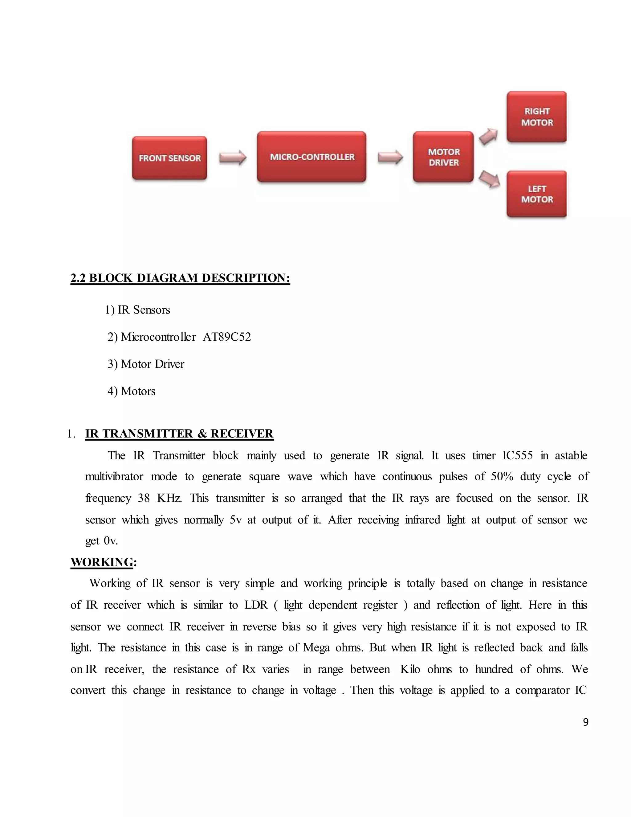
1 PROJECT REPORT ON “OBSTACLE AVOIDING ROBOT” BACHELOR OF TECHNOLOGY IN ELECTRONICS & COMMUNICATION ENGINEERING BHARAT INSTITUE OF ENGINEERING & TECHNOLOGY JNTUH: HYDERABAD 2014-2015 Submitted To:- Submitted By:- Lect.in ECE Deptt. Umera Anjum (12E15A0401)
2 BHARAT INSTITUTE OF ENGINEERING AND TECHNOLOGY Mangalpally (V), Ibrahimpatnam (M), R.R.DIST-501510 Aug 2014 Department of Electronics and Communication Engineering CERTIFICATE This is to certify that the project work entitled “OBSTACLE AVOIDING ROBOT” is carried out by K. Sri Arun Sai (11E11A0443), Umera Anjum (12E15A0401) in partial fulfillment for the award of degree of BACHELOR OF TECHNOLOGY in Electronics and Communication Engineering, Jawaharlal Nehru Technological University, Hyderabad during the academic year 2011- 15. INTERNAL GUIDE HEAD OF THE DEPARTMENT Prof. G. Kumaraswamy Rao EXTERNAL EXAMINER
3 ACKNOWLEDGMENT We owe a great many thanks to many people who have helped and supported us throughout this project, which would not have taken shape without their co-operation. Thanks to all. We express our profound gratitude to Sri CH. Venugopal Reddy, Secretary and indebtedness to our management, BHARAT INSTITUTE OF ENGINEERING & TECHNOLOGY, IBRAHIMPATNAM for their constructive criticism. We would like to specially thank our beloved Head, Department of ECE, Prof. G. Kumaraswamy Rao, for his guidance, inspiration and constant encouragement throughout this research work. We would like to express our deep gratitude to our Project Coordinator Mr. E. Venkat Reddy, Associate Professor and Mr. Jogi Raju, Associate Professor for providing us an opportunity to work and guiding in our college. We convey our thanks to our Internal Guide ________________Assistant Professor for his timely guidance, moral support and personal supervision throughout the project. These few words would never be complete if we were not to mention our thanks to our parents, department laboratory, staff members and all friends without whose co-operation this project could not have become a reality. By, K. Sri Arun Sai (11E11A0443) Umera Anjum (12E15A0401)
4 ABSTRACT Robotics is a branch of science that deals with Mechanical, Electrical and Software fields. Robots are the machines that are used in our day-to-day to life to reduce men power and work accurately without any distortions. Robots can be classified into two different sections basing upon their skills as Automated and Manual. Obstacle detector is a Automated robot which itself recognizes the obstacle in its path and moves in free direction. Robot detects the obstacle by using two IR Sensors placed in front. The IR sensors are placed on left and right side of the robot through which continuous Infrared radiation is emitted for detection of obstacles in the path. These IR Sensors are connected to a controlling element AT89c51 µc. When a obstacle is placed in the path of robot IR beam is reflected to the sensor from the obstacle. On detecting obstacle in the path sensor sends 0 volts to µc. This 0 voltage is detected by Microcontroller which avoids the obstacle by taking left or right turn. Similarly if the sensor sends +5v to Microcontroller, the Microcontroller assumes it as clear path and makes the robot to move in straight. Two motors namely right motor and left motor are connected to Motor driver IC (L293D). L293D is interface with Microcontroller. Microcontroller sends logic 0 & logic 1 as per the programming to driver IC which makes motors to rotate in clockwise and anticlockwise direction. Wheels attached to the motors rotate accordingly with the motor shaft causing in the moment of the robot by wheels. In front portion of the robot a free wheel is attached to move the robot easily in any direction as per the requirement. A 12Volts DC battery is attached to the circuit. As the microcontroller and sensors requires only 5v, set of resistors and capacitors are used to supply 5v DC to them. Power Management System is not maintained in the circuit as the battery can be removed after the usage of robot. So it does not cause any loss in the power of battery. This type of robots has multiple applications in various fields. They can be used to know the strength of the opposite army in defense system. They can be used as floor and wall cleaners. They are used in automated GPS vehicles to calculate the moment of the vehicle overhead. These robots are easy to construct and cheaper in cost with long durability. INDEX
5 CHAPTER PAGE NO. CERTIFICATE (i) ACKNOWLEDGEMENT (ii) 1. INTRODUCTION TO EMBEDDED SYSTEMS 1.1 INTRODUCTION 1 2.1 CHARACTERSTICS 1 3.1 APPLICATIONS 2 2. INTRODUCTION TO OBSTACLE AVOIDING ROBOT 2.1 INTRODUCTION 3 2.2 BLOCK DIAGRAM 5 2.3 BLOCK DIAGRAM DESCRIPTION 5 3. HARDWARE DESCRIPTION 3.1 HARDWARE MODULES 10 3.2 HARWARE MODULES DESCRIPTION 10 3.3. CIRCUIT DIAGRAM 3.4 CIRCUIT DIAGRAM 23 3.5 CIRCUIT LEVEL DESCRIPTION 24 4. PROGRAMMING OF OBSTACLE AVOIDING ROBOT 33 CONCLUSION 41 CHAPTER-1
6 1. INTRODUCTION TO THE DEPARTMENT 1.1 INTORDUTION: An embedded system is a computer system designed to perform one or a few dedicated functions often with real-time computing constraints. It is embedded as part of a complete device often including hardware and mechanical parts. By contrast, a general-purpose computer, such as a personal computer (PC), is designed to be flexible and to meet a wide range of end-user needs. Embedded systems control many devices in common use today. Embedded systems are controlled by one or more main processing cores that is typically either a microcontroller or a digital signal processor (DSP). The key characteristic is however being dedicated to handle a particular task, which may require very powerful processors. Since the embedded system is dedicated to specific tasks, design engineers can optimize it reducing the size and cost of the product and increasing the reliability and performance. 1.2 CHARACTERISTICS 1. Embedded systems are designed to do some specific task, rather than be a general-purpose computer for multiple tasks. Some also have real-time performance constraints that must be met, for reasons such as safety and usability others may have low or no performance requirements, allowing the system hardware to be simplified to reduce costs. 2. Embedded systems are not always stand alone devices. Many embedded systems consist of small, computerized parts within a larger device that serves a more general purpose. 3. The program instructions written for embedded systems are referred to as firmware, and are stored in read-only memory or Flash memory chips. They run with limited computer hardware resources: little memory, small or non-existent keyboard and/or screen. 1.3 APPLICATIONS: Embedded controllers may be found in many different kinds of system and are used for many different applications. Such as: ● Manufacturing and process control ● Construction industry
7 ● Transport ● Buildings and premises ● Domestic service ● Communications ● Office system and mobile equipment ● Medical diagnostics, monitoring and life support ● Testing ,monitoring and diagnostic system ● Banking, finance and commercial
8 CHAPTER-2 INTRODUCTION TO OBSTACLE AVOIDING ROBOT Robotics is part of Today's communication. In today’s world ROBOTICS is fast growing and interesting field. It is simplest way for latest technology modification. Now a day's communication is part of advancement of technology, so we decided to work on ROBOTICS field, and design something which will make human life simpler in day today aspect. Thus we are supporting this cause. This project is basic stage of any automatic robot. This ROBOT has sufficient intelligence to cover the maximum area of provided space. It has a infrared sensor which are used to sense the obstacles coming in between the path of ROBOT. It will move in a particular direction and avoid the obstacle which is coming in its path. We have used two D.C motors to give motion to the ROBOT. The construction of the ROBOT circuit is easy and small .The electronics parts used in the ROBOT circuits are easily available and cheap too. The project uses μc AT89C52 as the controlling element. It uses IR (Infra Red) sensors and two IR transmitting circuitry. When the obstacle comes in path of robot IR beam is reflected from the obstacle then sensor gives zero voltage to μc. This zero voltage is detected then μc decides to avoid the obstacle by taking left or right turn. If the sensor gives +5v to μc that means there is no obstacle present in its path so it goes straight until any obstacle is detected. The two IR transmitter circuits are fitted in front on right and left side of robot. The two IR sensors are placed near to transmitters’ IR LEDs. The connections can be given from main circuit to sensors using simple twisted pair cables. Two motors namely right motor and left motor are connected to driver IC (L293D). L293D is interface with μc. Micro-controller sends logic 0 & logic 1 as per the programming to driver IC which moves motors forward or reverse direction. 2.1 BLOCK DIAGRAM:
9 2.2 BLOCK DIAGRAM DESCRIPTION: 1) IR Sensors 2) Microcontroller AT89C52 3) Motor Driver 4) Motors 1. IR TRANSMITTER & RECEIVER The IR Transmitter block mainly used to generate IR signal. It uses timer IC555 in astable multivibrator mode to generate square wave which have continuous pulses of 50% duty cycle of frequency 38 KHz. This transmitter is so arranged that the IR rays are focused on the sensor. IR sensor which gives normally 5v at output of it. After receiving infrared light at output of sensor we get 0v. WORKING: Working of IR sensor is very simple and working principle is totally based on change in resistance of IR receiver which is similar to LDR ( light dependent register ) and reflection of light. Here in this sensor we connect IR receiver in reverse bias so it gives very high resistance if it is not exposed to IR light. The resistance in this case is in range of Mega ohms. But when IR light is reflected back and falls on IR receiver, the resistance of Rx varies in range between Kilo ohms to hundred of ohms. We convert this change in resistance to change in voltage . Then this voltage is applied to a comparator IC
10 which compare it with a threshold level (defined by us according to required range and sensitivity ).If voltage of sensor is more than threshold then output is high else it is low (depends on your connection to comparator ) which can be used directly for microcontroller IR sensor is nothing but a diode, which is sensitive for infrared radiation. This infrared transmitter and receiver is called as IR TX-RX pair. Color of IR transmitter and receiver is different. 2. Microcontroller : This is the most important block of the system. Microcontroller is the decision making logical device which has its own memory, I/O ports, CPU and Clock circuit embedded on a single chip. 3. MOTOR DRIVER: The MCU cannot drive the motors (used to actually make the robot run) directly, so a motor driver is used. L293D is used as driver IC. Motors are connected to this IC. According to program in μc it drives the left and right motor. 4. MOTOR Motor are used for the movement of the robot .here we use the dc motor as it has the principle of speed controlling. CHAPTER-3 HARDWARE IMPLIMENTATION This chapter briefly explains about the hardware implementation of the project. It discusses about design and working of the design with the help of block diagram and circuit diagram and explanation of circuit diagram in detail. 3.1. Schematic Diagram:
11 3.2CIRCUIT DESCRIPTION: Basically the circuit consists of the following blocks:- ● Power supply ● Sensors ● Microcontroller AT89C52 ● Motor driver
12 ● Motors Let us take the overview of each block one by one 3.2.1POWER SUPPLY CIRCUIT: The input to the circuit is applied from the regulated power supply. The a.c. input i.e.,230V from the mains supply is step down by transformer to 12V and is fed to the rectifier. The output obtained from the rectifier is pulsating d.c voltage. So in order to get a pure d.c voltage, the output voltage from the rectifier is fed to a filter to remove any a.c components present even after rectification. Now, this voltage is given to a voltage regulator to obtain a pure constant dc voltage. TRANSFORMERS: Usually, Dc voltages are required to operate various electronic equipment and these voltages are 5v,9v or 12v. but these voltages cannot be obtained directly. Thus the a.c. input available at mains
13 supply i.e.,230v is to be brought down to the required voltages level. This is done by a transformer. Thus, a step down transformer is employed to decrease the voltage to a required level. RECTIFIER: The output from the transformer is fed to the rectifier. It converts a.c into pulsating d.c. the rectifier may be a half wave or a full wave rectifier. In this project, a bridge rectifier is used because of its merits like good stability and full wave rectification. FILTER: Capacitive filter is used in this project. It removes the ripples from the output of the rectifier and smoothens the d.c output received from this filters is constant until the mains voltage and load is maintained constant.however, if either of the two is varied, d.c voltage received at this point changes. Therefore a regulator is applied at the output. 3.2.2 VOLTAGE REGULATOR: As the name itself implies, it regulates the input applied to it. A voltage regulator is an electrical regulator designed to automatically maintain a constant voltage level. In this project, a power supply of 5v and 12v are required. In order to obtain these voltage levels, 7805 and 7812 voltage regulators are to be used. The first 78 represents positive supply and the number 05,12 represents the required output voltage levels.
14 Fig: 4.2 voltage regulator 7805 e.g voltages.,7805 (5 V), 7806 (6 V), 7808 (8 V), 7810 (10 V), 7812(12 V), 7815 (15 V), 7818 (18 V), and 7824 (24 V).These devices can handle a maximum output current of 1.5 A if properly heat-sunk. To remove unwanted input or output spikes/noise, capacitors can be attached to the regulator’s input and output terminals. 3.3 HARDWARE MODULES: The hardware modules of this project are: ● Microcontroller
15 ● Motor driver ● Motor 3.3 HARDWARE MODULE DISCRIPITON: 3.3.1 MICROCONTROLLER (AT89C52):- The AT89C52 is a low power ,high performance CMOS 8 bit microcomputer with 8k bytes of flash programmable and erasable read only memory .The device is manufactured using Atmel’s high density nonvolatile memory technology and is compatible with the industry standard 80C51 and 80C52 instrution set and pinout . The on-chip flash allows the program memory to be reprogrammed in system or by a conventional nonvolatile memory programmer.By combining a versatile 8-bit CPU with Flash on a monolithic chip, the Atmel AT89C52 is a powerful with Flash on a monolithic chip, the Atmel AT89C52 is a powerful microcomputer with Flash on a monolithic chip, the Atmel AT89C52 is a powerful microcomputer 3.3.2 FEATURES: ● Compatible with MCS-51™ Products ● K Bytes of In-System Reprogrammable Flash Memory ● Endurance: 1,000 Write/Erase Cycles ● Fully Static Operation: 0 Hz to 24 MHz ● Three-level Program Memory Lock ● 256 x 8-bit Internal RAM ● 32 Programmable I/O Lines ● Three 16-bit Timer/Counters ● Eight interrupt sources
16 3.3.3 PIN DIAGRAM: Figure: 3.1 pin diagram of 8051 3.3.4 PIN DESCRIPTION: VCC -Supply voltage. GND-Ground PORT 0- Port 0 is an 8-bit open drain bidirectional I/O port.As an output port, each pin can sink eight TTL inputs. When 1s are written to port 0 pins, the pins can be used as high impedance inputs Port 0 can also be configured to be the multiplexed loworder address/data bus during accesses to external program and data memory. In this mode, P0 has internal pullups.Port 0 also receives the code bytes during Flash programming and outputs the code bytes during program verification.External pull ups are required during program verification.
17 PORT 1- Port 1 is an 8-bit bidirectional I/O port with internal pullups.The Port 1 output buffers can sink/source four TTL inputs.When 1s are written to Port 1 pins, they are pulled high bythe internal pullups and can be used as inputs. As inputs Port 1 pins that are externally being pulled low will source current (IIL) because of the internal pullups. PORT 2- Port 2 is an 8-bit bidirectional I/O port with internal pullups.The Port 2 output buffers can sink/source four TTL inputs.When 1s are written to Port 2 pins, they are pulled high bythe internal pullups and can be used as inputs. As inputs,Port 2 pins that are externally being pulled low will sourcecurrent (IIL) because of the internal pullups.Port 2 emits the high-order address byte during fetches from external program memory and during accesses toexternal data memory that use 16-bit addresses (MOVX @DPTR). In this application, Port 2 uses strong internal pullupswhen emitting 1s. During accesses to external data memory that use 8-bit addresses (MOVX @ RI), Port 2emits the contents of the P2 Special Function Register.Port 2 also receives the high-order address bits and somecontrol signals during Flash programming and verification. PORT 3- Port 3 is an 8-bit bidirectional I/O port with internal pullups.The Port 3 output buffers can sink/source four TTL inputs.When 1s are written to Port 3 pins, they are pulled high bythe internal pullups and can be used as inputs. As inputs,Port 3 pins that are externally being pulled low will sourcecurrent (IIL) because of the pullups.Port 3 also serves the functions of various special features of the AT89C51, as shown in the following table.Port 3 also receives some control signals for Flash programming and verification. Port Pin Alternate Functions P3.0 RXD (serial input port) P3.1 TXD (serial output port) P3.2 INT0 (external interrupt 0) P3.3 INT1 (external interrupt 1) P3.4 T0 (timer 0 external input)
18 P3.5 T1 (timer 1 external input) P3.6 WR (external data memory write strobe) P3.7 RD (external data memory read strobe) RST- Reset input. A high on this pin for two machine cycles while the oscillator is running resets the device. ALE/PROG- Address Latch Enable is an output pulse for latching the low byte of the address during accesses to external memory.This pin is also the program pulse input (PROG) duringFlash programming.In normal operation, ALE is emitted at a constant rate of 1/6the oscillator frequency and may be used for external timing or clocking purposes. Note, however, that one ALE pulse is skipped during each access to external data memory.If desired, ALE operation can be disabled by setting bit 0 ofSFR location 8EH. With the bit set, ALE is active only during a MOVX or MOVC instruction. Otherwise, the pin is weakly pulled high. Setting the ALE-disable bit has noeffect if the microcontroller is in external execution mode. PSEN- Program Store Enable is the read strobe to external program memory.When the AT89C52 is executing code from external program memory, PSEN is activated twice each machine cycle, except that two PSEN activations are skipped during each access to external data memory. EA/VPP- External Access Enable. EA must be strapped to GND in order to enable the device to fetch code from external program memory locations starting at 0000H up to FFFFH.Note, however, that if lock bit 1 is programmed, EA will be internally latched on reset.EA should be strapped to VCC for internal program executions. This pin also receives the 12-volt programming enable voltage(VPP) during Flash programming when 12-volt programming is selected. XTAL1 Input to the inverting oscillator amplifier and input to the internal clock operating circuit.
19 XTAL2 Output from the inverting oscillator amplifier. Oscillator Characteristics XTAL1 and XTAL2 are the input and output, respectively,of an inverting amplifier that can be configured for use as an on-chip oscillator, as shown in Figure 7. Either a quartz crystal or ceramic resonator may be used. To drive the device from an external clock source, XTAL2 should be left unconnected while XTAL1 is driven. There are no requirements on the duty cycle of the external clock signal, since the input to the internal clocking circuitry is through a divide-by-two flip-flop, but minimum and maximum voltage high and low time specifications must be 3.3.5 BLOCK DIAGRAM:
20 3.4 MOTOR DRIVER: The L293d is a quadruple high-current half-H driver designed to provide bidirectional drive currents of up to 1 A at voltages from 4.5 V to 36 V. It is designed to drive inductive loads such as relays,solenoids, dc and bipolar stepping motors, as wellas other high-current/high-voltage loads in positive-supply applications.All inputs are TTL compatible. Each output is a complete totem-pole drive circuit with a Darlington transistor sink and a pseudo-Darlington source.
21 Drivers are enabled in pairs with drivers 1 and 2 enabled by 1,2EN and drivers 3 and 4 enabled by3,4EN. When an enable input is high, the associated drivers are enabled and their outputs are active and in phase with their inputs. When the enable input is low, those drivers are disabled and their outputs are off and in a high-impedance state. With the proper data inputs, each pair of drivers form a full-H (or bridge) reversible drive suitable for solenoid or motor applications. External high-speed output clamp diodes should be used for inductive transient suppression. AVCC1 terminal, separate from VCC2, is provided for the logic inputs to minimize device power dissipation. The L293d is designed for operation from 0°C TOP VIEW OF L293D: Figure : 3.4 top view of L293D 3.4.1 FEATURES: ● 1-A Output Current Capability Per Driver ● Pulsed Current 2-A Driver ● Wide Supply Voltage Range: 4.5 V to 36 V ● Separate Input-Logic Supply ● NE Package Designed for Heat Sinking ● Thermal Shutdown ● Internal ESD Protection ● High-Noise-Immunity Inputs 3.4.2 MOTOR:
22 A direct current (DC) motor is another widely used device that translates electrical pulses into mechanical movement. In the DC motor we have only + and - leads. Connecting them to a DC voltage source moves the motor in one direction. By reversing the polarity, the DC motor will move in the opposite direction. One can easily experiment with the DC motor. For example, small fans used in many motherboards to cool the CPU are run by DC motors. By connecting their leads to the + and - voltage source, the DC motor moves. While a stepper motor moves in steps of 1 to 15 degrees, the DC motor moves continuously. In a stepper motor, if we know the starting position we can easily count the number of steps the motor has moved and calculate the final position of the motor. This is not possible in a DC motor. The maximum speed of a DC motor is indicated in rpm and is given in the data sheet. The DC motor has two rpms: no-load and loaded. The manufacturer's data sheet gives the no-load rpm. The no- load rpm can be from a few thousand to tens of thousands. The rpm is reduced when moving a load and it decreases as the load is increased. For example, a drill turning a screw has a much lower rpm speed than when it is in the no-load situation. DC motors also have voltage and current ratings. The nominal voltage is the voltage for that motor under normal conditions, and can be from 1 to 150V, depending on the motor. As we increase the voltage, the rpm goes up. The current rating is the current consumption when the nominal voltage is applied with no load, and can be from 25mA to a few amps. As the load increases, the rpm is decreased, unless the current or voltage provided to the motor is increased, which in turn increases the torque. With a fixed voltage, as the load increases, the current (power) consumption of a DC motor is increased. If we overload the motor it will stall, and that can damage the motor due to the heat generated by high current consumption.
23 3.4.1ADVANTAGES: ● Easy to understand design ● Easy to control speed ● Easy to control torque ● Simple ,cheap drive design 3.5 MOTOR DRIVER (L293D): From microcontroller we cannot connect a motor directly because microcontroller can not give sufficient current to drive the DC motors. Motor driver is a current enhancing device, it can also be act as Switching Device. Thus we insert motor driver in between motor and microcontroller.Motor driver take the input signals from microcontroller and generate corresponding output for motor. L293D- This is a motor driver IC that can drive two motor simultaneously.
24 POINTS REGARDING L293D: Supply voltage (Vss) is the Voltage at which we wish to drive the motor. Generally we prefer 6V for dc motor and 6 to 12V for gear motor, depending upon the rating of the motor.Logical Supply Voltage will decide what value of input voltage should be considered as high or low .So if we set Logical Supply Voltage equals to +5V,then -0.3V to 1.5V will be considered as Input Low Voltage and 2.3 V to 5V will be considered as Input High Voltage. ➢ L293D has 2 Channels .One channel is used for one motor. Channel 1 - Pin 1 to 8 Channel 2 - Pin 9 to 16 ➢ Enable Pin is use to enable or to make a channel active .Enable pin is also called as Chip Inhibit Pin. ➢ All Input (Pin No. 2, 7,10and 15) of L293D IC is the output from microcontroller . ➢ All Output (Pin No. 3, 6,11and 14) of L293D IC goes to the input of Right and Left motor. OUTPUT CONNECTIONS: OUTPUT 1 (Pin No 3) --- Negative Terminal of Right Motor
25 OUTPUT 2 (Pin No 6) --- Positive Terminal of Right Motor OUTPUT 3 (Pin No 10) --- Positive Terminal of Left Motor OUTPUT 4 (Pin No 14) --- Negative Terminal of Left Motor For one motor: Table4.1 motor movement Positive Terminal Negative Terminal Motor Output 0 0 No Movement Vss 0 Straight 0 Vss Reverse Vss Vss No Movement One channel corresponds to one motor. ➢ Enable pin should be high for activating the corresponding channel. Input 1 corresponds to Output 1. ➢ If Enable 1=High (1) Input1 =High (1), Output1=Vss Input1 =Low (0), Output1=0 ➢ If Enable 1=Low (0) Input1 =High (1), Output1=0 Input1 =Low (0), Output1=0 Means if Enable pin low, the output will be at 0 always. If its high output depend on input
26 MOTOR OUTPUT SYSTEM: For moving a robot we have two dc motors attached to wheels gears. WHY DC MOTORS: DC motors are most easy to control. One dc motor requires only two signals for its operation. If we want to change its direction just reverse the polarity of power supply across it. We can vary speed by varying the voltage across motor. WHY TWO MOTORS: By using two motors we can move our robot in any direction. This steering mechanism of robot is called as differential drive.
27 Left Motor Right Motor Robot Movement Straight Straight Straight Stop Straight Left Reverse Straight Sharp Left Straight Stop Right Straight Reverse Sharp right
28 Reverse Reverse Reverse 3.6 SENSORS:- The IR Transmitter block mainly used to generate IR signal. It uses timer IC555 in astable multivibrator mode to generate square wave which have continuous pulses of 50% duty cycle of frequency 38 KHz. This transmitter is so arranged that the IR rays are focused on the sensor. IR sensor which gives normally 5v at output of it. After receiving infrared light at output of sensor we get 0v.
29 CHAPTER-5 SOFTWARE IMPLIMENTATION Software tools required: Keil µv3, Proload are the two software tools used to program microcontroller. The working of each software tool os explained below in details. 5.1 PROGRAMING MICROCONTROLLER A complier for a high level language helps to reduce production time. To program th AT89S52 microcontroller the keil µV3 is used. The programming is done strictly in the embedded C language. The compilation of the C program converts it into machine language file (.hex).this is the only language the micro controller will understand, because it contains the original program code converted into hex decimal format. During this step there are some warnings about eventual errors in the program. This is shown in fig. below.
30 Fig. Compilation source code 5.1.1 KEIL Compiler Keil complier is software used where the machine language code is written and compiled. After compilation, the machine source code is converted into hex code which is to be dumped into the microcontroller for further processing. Keil compiler also supports C language code. 5.1.2. PROLOAD Proload is software which accepts only hex files. Once the machine code is converted into hex code,that hex code has to be dumped into the micro controller and this is done by the proload. Proload programmer which itself contains a micro controller in it other than the one which is to be programmed. This micro controller has a program in it written in such away that it accepts the hex file from keil compiler and dumps this hex file into the microcontroller which is to be programmed. As the proload programmer kit requires power supply to be operated,this power supply is given from the power supply circuit designed above. It should be noted that this programmer kit contains power supply section board itself in order to switch on that power supply, a source is required. Thus this is accomplished from the power supply board with an output of 12V. Features: ● Supports major Atmel 89 series devices ● Auto identify connected hardware and devices ● Error checking and verification in built ● Lock of programs in chip supported to prevent program copying
31 ● 20-40 pins ZIF socket on board ● Auto Erase before writing and Auto verify after writing ● Informative status bar and access to latest programmed file ● Simple and easy to use ● Works on 57600 speed CODING: #include<reg51.h> //Motor connections sbit en1=P2^0; sbit in1 =P2^2; sbit in 2=P2^3; sbit En 2=P2^1; sbit in3= P2^4; sbit in4= P2^5; // IR Sensor sbit ir1= P1^1; //right sbit ir2= P1^2; //left void main( ) { ir1=ir2=0; en1=en2=in3=in4=in1=in2=0; while( 1) {
32 en1=1; en2=1; if (ir1==0 && ir2==0) { in1=1; in2=0; in3=1; in4=0; delay(); } //forward if (ir1==0 && ir2==1) { en1=1; in1=1; in2=0; en2=0; in3=0; in4=0; delay(); } //right if (ir1==1 && ir2==0) { in1=0; in2=0;
33 in3=1; in4=0; delay(); } //left if (ir1==1 && ir2==1) { in1=0; in2=1; in3=0; in4=1; //back delay(); } } } Void delay () { int i; for (i=0;i<=500;i++) }
34 CONCLUSION The project is “obstacle detection and the avoidance robot” is practically proved by using the IR pairs for sensing the robot, h bridge for the driving the dc motor, dc motor isused for the movement of the robot with the help of the micro controller.

Obstacle avoiding robot.doc

  • 1.
    1 PROJECT REPORT ON “OBSTACLE AVOIDINGROBOT” BACHELOR OF TECHNOLOGY IN ELECTRONICS & COMMUNICATION ENGINEERING BHARAT INSTITUE OF ENGINEERING & TECHNOLOGY JNTUH: HYDERABAD 2014-2015 Submitted To:- Submitted By:- Lect.in ECE Deptt. Umera Anjum (12E15A0401)
  • 2.
    2 BHARAT INSTITUTE OFENGINEERING AND TECHNOLOGY Mangalpally (V), Ibrahimpatnam (M), R.R.DIST-501510 Aug 2014 Department of Electronics and Communication Engineering CERTIFICATE This is to certify that the project work entitled “OBSTACLE AVOIDING ROBOT” is carried out by K. Sri Arun Sai (11E11A0443), Umera Anjum (12E15A0401) in partial fulfillment for the award of degree of BACHELOR OF TECHNOLOGY in Electronics and Communication Engineering, Jawaharlal Nehru Technological University, Hyderabad during the academic year 2011- 15. INTERNAL GUIDE HEAD OF THE DEPARTMENT Prof. G. Kumaraswamy Rao EXTERNAL EXAMINER
  • 3.
    3 ACKNOWLEDGMENT We owe agreat many thanks to many people who have helped and supported us throughout this project, which would not have taken shape without their co-operation. Thanks to all. We express our profound gratitude to Sri CH. Venugopal Reddy, Secretary and indebtedness to our management, BHARAT INSTITUTE OF ENGINEERING & TECHNOLOGY, IBRAHIMPATNAM for their constructive criticism. We would like to specially thank our beloved Head, Department of ECE, Prof. G. Kumaraswamy Rao, for his guidance, inspiration and constant encouragement throughout this research work. We would like to express our deep gratitude to our Project Coordinator Mr. E. Venkat Reddy, Associate Professor and Mr. Jogi Raju, Associate Professor for providing us an opportunity to work and guiding in our college. We convey our thanks to our Internal Guide ________________Assistant Professor for his timely guidance, moral support and personal supervision throughout the project. These few words would never be complete if we were not to mention our thanks to our parents, department laboratory, staff members and all friends without whose co-operation this project could not have become a reality. By, K. Sri Arun Sai (11E11A0443) Umera Anjum (12E15A0401)
  • 4.
    4 ABSTRACT Robotics is abranch of science that deals with Mechanical, Electrical and Software fields. Robots are the machines that are used in our day-to-day to life to reduce men power and work accurately without any distortions. Robots can be classified into two different sections basing upon their skills as Automated and Manual. Obstacle detector is a Automated robot which itself recognizes the obstacle in its path and moves in free direction. Robot detects the obstacle by using two IR Sensors placed in front. The IR sensors are placed on left and right side of the robot through which continuous Infrared radiation is emitted for detection of obstacles in the path. These IR Sensors are connected to a controlling element AT89c51 µc. When a obstacle is placed in the path of robot IR beam is reflected to the sensor from the obstacle. On detecting obstacle in the path sensor sends 0 volts to µc. This 0 voltage is detected by Microcontroller which avoids the obstacle by taking left or right turn. Similarly if the sensor sends +5v to Microcontroller, the Microcontroller assumes it as clear path and makes the robot to move in straight. Two motors namely right motor and left motor are connected to Motor driver IC (L293D). L293D is interface with Microcontroller. Microcontroller sends logic 0 & logic 1 as per the programming to driver IC which makes motors to rotate in clockwise and anticlockwise direction. Wheels attached to the motors rotate accordingly with the motor shaft causing in the moment of the robot by wheels. In front portion of the robot a free wheel is attached to move the robot easily in any direction as per the requirement. A 12Volts DC battery is attached to the circuit. As the microcontroller and sensors requires only 5v, set of resistors and capacitors are used to supply 5v DC to them. Power Management System is not maintained in the circuit as the battery can be removed after the usage of robot. So it does not cause any loss in the power of battery. This type of robots has multiple applications in various fields. They can be used to know the strength of the opposite army in defense system. They can be used as floor and wall cleaners. They are used in automated GPS vehicles to calculate the moment of the vehicle overhead. These robots are easy to construct and cheaper in cost with long durability. INDEX
  • 5.
    5 CHAPTER PAGE NO. CERTIFICATE(i) ACKNOWLEDGEMENT (ii) 1. INTRODUCTION TO EMBEDDED SYSTEMS 1.1 INTRODUCTION 1 2.1 CHARACTERSTICS 1 3.1 APPLICATIONS 2 2. INTRODUCTION TO OBSTACLE AVOIDING ROBOT 2.1 INTRODUCTION 3 2.2 BLOCK DIAGRAM 5 2.3 BLOCK DIAGRAM DESCRIPTION 5 3. HARDWARE DESCRIPTION 3.1 HARDWARE MODULES 10 3.2 HARWARE MODULES DESCRIPTION 10 3.3. CIRCUIT DIAGRAM 3.4 CIRCUIT DIAGRAM 23 3.5 CIRCUIT LEVEL DESCRIPTION 24 4. PROGRAMMING OF OBSTACLE AVOIDING ROBOT 33 CONCLUSION 41 CHAPTER-1
  • 6.
    6 1. INTRODUCTION TOTHE DEPARTMENT 1.1 INTORDUTION: An embedded system is a computer system designed to perform one or a few dedicated functions often with real-time computing constraints. It is embedded as part of a complete device often including hardware and mechanical parts. By contrast, a general-purpose computer, such as a personal computer (PC), is designed to be flexible and to meet a wide range of end-user needs. Embedded systems control many devices in common use today. Embedded systems are controlled by one or more main processing cores that is typically either a microcontroller or a digital signal processor (DSP). The key characteristic is however being dedicated to handle a particular task, which may require very powerful processors. Since the embedded system is dedicated to specific tasks, design engineers can optimize it reducing the size and cost of the product and increasing the reliability and performance. 1.2 CHARACTERISTICS 1. Embedded systems are designed to do some specific task, rather than be a general-purpose computer for multiple tasks. Some also have real-time performance constraints that must be met, for reasons such as safety and usability others may have low or no performance requirements, allowing the system hardware to be simplified to reduce costs. 2. Embedded systems are not always stand alone devices. Many embedded systems consist of small, computerized parts within a larger device that serves a more general purpose. 3. The program instructions written for embedded systems are referred to as firmware, and are stored in read-only memory or Flash memory chips. They run with limited computer hardware resources: little memory, small or non-existent keyboard and/or screen. 1.3 APPLICATIONS: Embedded controllers may be found in many different kinds of system and are used for many different applications. Such as: ● Manufacturing and process control ● Construction industry
  • 7.
    7 ● Transport ● Buildingsand premises ● Domestic service ● Communications ● Office system and mobile equipment ● Medical diagnostics, monitoring and life support ● Testing ,monitoring and diagnostic system ● Banking, finance and commercial
  • 8.
    8 CHAPTER-2 INTRODUCTION TO OBSTACLEAVOIDING ROBOT Robotics is part of Today's communication. In today’s world ROBOTICS is fast growing and interesting field. It is simplest way for latest technology modification. Now a day's communication is part of advancement of technology, so we decided to work on ROBOTICS field, and design something which will make human life simpler in day today aspect. Thus we are supporting this cause. This project is basic stage of any automatic robot. This ROBOT has sufficient intelligence to cover the maximum area of provided space. It has a infrared sensor which are used to sense the obstacles coming in between the path of ROBOT. It will move in a particular direction and avoid the obstacle which is coming in its path. We have used two D.C motors to give motion to the ROBOT. The construction of the ROBOT circuit is easy and small .The electronics parts used in the ROBOT circuits are easily available and cheap too. The project uses μc AT89C52 as the controlling element. It uses IR (Infra Red) sensors and two IR transmitting circuitry. When the obstacle comes in path of robot IR beam is reflected from the obstacle then sensor gives zero voltage to μc. This zero voltage is detected then μc decides to avoid the obstacle by taking left or right turn. If the sensor gives +5v to μc that means there is no obstacle present in its path so it goes straight until any obstacle is detected. The two IR transmitter circuits are fitted in front on right and left side of robot. The two IR sensors are placed near to transmitters’ IR LEDs. The connections can be given from main circuit to sensors using simple twisted pair cables. Two motors namely right motor and left motor are connected to driver IC (L293D). L293D is interface with μc. Micro-controller sends logic 0 & logic 1 as per the programming to driver IC which moves motors forward or reverse direction. 2.1 BLOCK DIAGRAM:
  • 9.
    9 2.2 BLOCK DIAGRAMDESCRIPTION: 1) IR Sensors 2) Microcontroller AT89C52 3) Motor Driver 4) Motors 1. IR TRANSMITTER & RECEIVER The IR Transmitter block mainly used to generate IR signal. It uses timer IC555 in astable multivibrator mode to generate square wave which have continuous pulses of 50% duty cycle of frequency 38 KHz. This transmitter is so arranged that the IR rays are focused on the sensor. IR sensor which gives normally 5v at output of it. After receiving infrared light at output of sensor we get 0v. WORKING: Working of IR sensor is very simple and working principle is totally based on change in resistance of IR receiver which is similar to LDR ( light dependent register ) and reflection of light. Here in this sensor we connect IR receiver in reverse bias so it gives very high resistance if it is not exposed to IR light. The resistance in this case is in range of Mega ohms. But when IR light is reflected back and falls on IR receiver, the resistance of Rx varies in range between Kilo ohms to hundred of ohms. We convert this change in resistance to change in voltage . Then this voltage is applied to a comparator IC
  • 10.
    10 which compare itwith a threshold level (defined by us according to required range and sensitivity ).If voltage of sensor is more than threshold then output is high else it is low (depends on your connection to comparator ) which can be used directly for microcontroller IR sensor is nothing but a diode, which is sensitive for infrared radiation. This infrared transmitter and receiver is called as IR TX-RX pair. Color of IR transmitter and receiver is different. 2. Microcontroller : This is the most important block of the system. Microcontroller is the decision making logical device which has its own memory, I/O ports, CPU and Clock circuit embedded on a single chip. 3. MOTOR DRIVER: The MCU cannot drive the motors (used to actually make the robot run) directly, so a motor driver is used. L293D is used as driver IC. Motors are connected to this IC. According to program in μc it drives the left and right motor. 4. MOTOR Motor are used for the movement of the robot .here we use the dc motor as it has the principle of speed controlling. CHAPTER-3 HARDWARE IMPLIMENTATION This chapter briefly explains about the hardware implementation of the project. It discusses about design and working of the design with the help of block diagram and circuit diagram and explanation of circuit diagram in detail. 3.1. Schematic Diagram:
  • 11.
    11 3.2CIRCUIT DESCRIPTION: Basically thecircuit consists of the following blocks:- ● Power supply ● Sensors ● Microcontroller AT89C52 ● Motor driver
  • 12.
    12 ● Motors Let ustake the overview of each block one by one 3.2.1POWER SUPPLY CIRCUIT: The input to the circuit is applied from the regulated power supply. The a.c. input i.e.,230V from the mains supply is step down by transformer to 12V and is fed to the rectifier. The output obtained from the rectifier is pulsating d.c voltage. So in order to get a pure d.c voltage, the output voltage from the rectifier is fed to a filter to remove any a.c components present even after rectification. Now, this voltage is given to a voltage regulator to obtain a pure constant dc voltage. TRANSFORMERS: Usually, Dc voltages are required to operate various electronic equipment and these voltages are 5v,9v or 12v. but these voltages cannot be obtained directly. Thus the a.c. input available at mains
  • 13.
    13 supply i.e.,230v isto be brought down to the required voltages level. This is done by a transformer. Thus, a step down transformer is employed to decrease the voltage to a required level. RECTIFIER: The output from the transformer is fed to the rectifier. It converts a.c into pulsating d.c. the rectifier may be a half wave or a full wave rectifier. In this project, a bridge rectifier is used because of its merits like good stability and full wave rectification. FILTER: Capacitive filter is used in this project. It removes the ripples from the output of the rectifier and smoothens the d.c output received from this filters is constant until the mains voltage and load is maintained constant.however, if either of the two is varied, d.c voltage received at this point changes. Therefore a regulator is applied at the output. 3.2.2 VOLTAGE REGULATOR: As the name itself implies, it regulates the input applied to it. A voltage regulator is an electrical regulator designed to automatically maintain a constant voltage level. In this project, a power supply of 5v and 12v are required. In order to obtain these voltage levels, 7805 and 7812 voltage regulators are to be used. The first 78 represents positive supply and the number 05,12 represents the required output voltage levels.
  • 14.
    14 Fig: 4.2 voltageregulator 7805 e.g voltages.,7805 (5 V), 7806 (6 V), 7808 (8 V), 7810 (10 V), 7812(12 V), 7815 (15 V), 7818 (18 V), and 7824 (24 V).These devices can handle a maximum output current of 1.5 A if properly heat-sunk. To remove unwanted input or output spikes/noise, capacitors can be attached to the regulator’s input and output terminals. 3.3 HARDWARE MODULES: The hardware modules of this project are: ● Microcontroller
  • 15.
    15 ● Motor driver ●Motor 3.3 HARDWARE MODULE DISCRIPITON: 3.3.1 MICROCONTROLLER (AT89C52):- The AT89C52 is a low power ,high performance CMOS 8 bit microcomputer with 8k bytes of flash programmable and erasable read only memory .The device is manufactured using Atmel’s high density nonvolatile memory technology and is compatible with the industry standard 80C51 and 80C52 instrution set and pinout . The on-chip flash allows the program memory to be reprogrammed in system or by a conventional nonvolatile memory programmer.By combining a versatile 8-bit CPU with Flash on a monolithic chip, the Atmel AT89C52 is a powerful with Flash on a monolithic chip, the Atmel AT89C52 is a powerful microcomputer with Flash on a monolithic chip, the Atmel AT89C52 is a powerful microcomputer 3.3.2 FEATURES: ● Compatible with MCS-51™ Products ● K Bytes of In-System Reprogrammable Flash Memory ● Endurance: 1,000 Write/Erase Cycles ● Fully Static Operation: 0 Hz to 24 MHz ● Three-level Program Memory Lock ● 256 x 8-bit Internal RAM ● 32 Programmable I/O Lines ● Three 16-bit Timer/Counters ● Eight interrupt sources
  • 16.
    16 3.3.3 PIN DIAGRAM: Figure:3.1 pin diagram of 8051 3.3.4 PIN DESCRIPTION: VCC -Supply voltage. GND-Ground PORT 0- Port 0 is an 8-bit open drain bidirectional I/O port.As an output port, each pin can sink eight TTL inputs. When 1s are written to port 0 pins, the pins can be used as high impedance inputs Port 0 can also be configured to be the multiplexed loworder address/data bus during accesses to external program and data memory. In this mode, P0 has internal pullups.Port 0 also receives the code bytes during Flash programming and outputs the code bytes during program verification.External pull ups are required during program verification.
  • 17.
    17 PORT 1- Port 1is an 8-bit bidirectional I/O port with internal pullups.The Port 1 output buffers can sink/source four TTL inputs.When 1s are written to Port 1 pins, they are pulled high bythe internal pullups and can be used as inputs. As inputs Port 1 pins that are externally being pulled low will source current (IIL) because of the internal pullups. PORT 2- Port 2 is an 8-bit bidirectional I/O port with internal pullups.The Port 2 output buffers can sink/source four TTL inputs.When 1s are written to Port 2 pins, they are pulled high bythe internal pullups and can be used as inputs. As inputs,Port 2 pins that are externally being pulled low will sourcecurrent (IIL) because of the internal pullups.Port 2 emits the high-order address byte during fetches from external program memory and during accesses toexternal data memory that use 16-bit addresses (MOVX @DPTR). In this application, Port 2 uses strong internal pullupswhen emitting 1s. During accesses to external data memory that use 8-bit addresses (MOVX @ RI), Port 2emits the contents of the P2 Special Function Register.Port 2 also receives the high-order address bits and somecontrol signals during Flash programming and verification. PORT 3- Port 3 is an 8-bit bidirectional I/O port with internal pullups.The Port 3 output buffers can sink/source four TTL inputs.When 1s are written to Port 3 pins, they are pulled high bythe internal pullups and can be used as inputs. As inputs,Port 3 pins that are externally being pulled low will sourcecurrent (IIL) because of the pullups.Port 3 also serves the functions of various special features of the AT89C51, as shown in the following table.Port 3 also receives some control signals for Flash programming and verification. Port Pin Alternate Functions P3.0 RXD (serial input port) P3.1 TXD (serial output port) P3.2 INT0 (external interrupt 0) P3.3 INT1 (external interrupt 1) P3.4 T0 (timer 0 external input)
  • 18.
    18 P3.5 T1 (timer1 external input) P3.6 WR (external data memory write strobe) P3.7 RD (external data memory read strobe) RST- Reset input. A high on this pin for two machine cycles while the oscillator is running resets the device. ALE/PROG- Address Latch Enable is an output pulse for latching the low byte of the address during accesses to external memory.This pin is also the program pulse input (PROG) duringFlash programming.In normal operation, ALE is emitted at a constant rate of 1/6the oscillator frequency and may be used for external timing or clocking purposes. Note, however, that one ALE pulse is skipped during each access to external data memory.If desired, ALE operation can be disabled by setting bit 0 ofSFR location 8EH. With the bit set, ALE is active only during a MOVX or MOVC instruction. Otherwise, the pin is weakly pulled high. Setting the ALE-disable bit has noeffect if the microcontroller is in external execution mode. PSEN- Program Store Enable is the read strobe to external program memory.When the AT89C52 is executing code from external program memory, PSEN is activated twice each machine cycle, except that two PSEN activations are skipped during each access to external data memory. EA/VPP- External Access Enable. EA must be strapped to GND in order to enable the device to fetch code from external program memory locations starting at 0000H up to FFFFH.Note, however, that if lock bit 1 is programmed, EA will be internally latched on reset.EA should be strapped to VCC for internal program executions. This pin also receives the 12-volt programming enable voltage(VPP) during Flash programming when 12-volt programming is selected. XTAL1 Input to the inverting oscillator amplifier and input to the internal clock operating circuit.
  • 19.
    19 XTAL2 Output from theinverting oscillator amplifier. Oscillator Characteristics XTAL1 and XTAL2 are the input and output, respectively,of an inverting amplifier that can be configured for use as an on-chip oscillator, as shown in Figure 7. Either a quartz crystal or ceramic resonator may be used. To drive the device from an external clock source, XTAL2 should be left unconnected while XTAL1 is driven. There are no requirements on the duty cycle of the external clock signal, since the input to the internal clocking circuitry is through a divide-by-two flip-flop, but minimum and maximum voltage high and low time specifications must be 3.3.5 BLOCK DIAGRAM:
  • 20.
    20 3.4 MOTOR DRIVER: TheL293d is a quadruple high-current half-H driver designed to provide bidirectional drive currents of up to 1 A at voltages from 4.5 V to 36 V. It is designed to drive inductive loads such as relays,solenoids, dc and bipolar stepping motors, as wellas other high-current/high-voltage loads in positive-supply applications.All inputs are TTL compatible. Each output is a complete totem-pole drive circuit with a Darlington transistor sink and a pseudo-Darlington source.
  • 21.
    21 Drivers are enabledin pairs with drivers 1 and 2 enabled by 1,2EN and drivers 3 and 4 enabled by3,4EN. When an enable input is high, the associated drivers are enabled and their outputs are active and in phase with their inputs. When the enable input is low, those drivers are disabled and their outputs are off and in a high-impedance state. With the proper data inputs, each pair of drivers form a full-H (or bridge) reversible drive suitable for solenoid or motor applications. External high-speed output clamp diodes should be used for inductive transient suppression. AVCC1 terminal, separate from VCC2, is provided for the logic inputs to minimize device power dissipation. The L293d is designed for operation from 0°C TOP VIEW OF L293D: Figure : 3.4 top view of L293D 3.4.1 FEATURES: ● 1-A Output Current Capability Per Driver ● Pulsed Current 2-A Driver ● Wide Supply Voltage Range: 4.5 V to 36 V ● Separate Input-Logic Supply ● NE Package Designed for Heat Sinking ● Thermal Shutdown ● Internal ESD Protection ● High-Noise-Immunity Inputs 3.4.2 MOTOR:
  • 22.
    22 A direct current(DC) motor is another widely used device that translates electrical pulses into mechanical movement. In the DC motor we have only + and - leads. Connecting them to a DC voltage source moves the motor in one direction. By reversing the polarity, the DC motor will move in the opposite direction. One can easily experiment with the DC motor. For example, small fans used in many motherboards to cool the CPU are run by DC motors. By connecting their leads to the + and - voltage source, the DC motor moves. While a stepper motor moves in steps of 1 to 15 degrees, the DC motor moves continuously. In a stepper motor, if we know the starting position we can easily count the number of steps the motor has moved and calculate the final position of the motor. This is not possible in a DC motor. The maximum speed of a DC motor is indicated in rpm and is given in the data sheet. The DC motor has two rpms: no-load and loaded. The manufacturer's data sheet gives the no-load rpm. The no- load rpm can be from a few thousand to tens of thousands. The rpm is reduced when moving a load and it decreases as the load is increased. For example, a drill turning a screw has a much lower rpm speed than when it is in the no-load situation. DC motors also have voltage and current ratings. The nominal voltage is the voltage for that motor under normal conditions, and can be from 1 to 150V, depending on the motor. As we increase the voltage, the rpm goes up. The current rating is the current consumption when the nominal voltage is applied with no load, and can be from 25mA to a few amps. As the load increases, the rpm is decreased, unless the current or voltage provided to the motor is increased, which in turn increases the torque. With a fixed voltage, as the load increases, the current (power) consumption of a DC motor is increased. If we overload the motor it will stall, and that can damage the motor due to the heat generated by high current consumption.
  • 23.
    23 3.4.1ADVANTAGES: ● Easy tounderstand design ● Easy to control speed ● Easy to control torque ● Simple ,cheap drive design 3.5 MOTOR DRIVER (L293D): From microcontroller we cannot connect a motor directly because microcontroller can not give sufficient current to drive the DC motors. Motor driver is a current enhancing device, it can also be act as Switching Device. Thus we insert motor driver in between motor and microcontroller.Motor driver take the input signals from microcontroller and generate corresponding output for motor. L293D- This is a motor driver IC that can drive two motor simultaneously.
  • 24.
    24 POINTS REGARDING L293D: Supplyvoltage (Vss) is the Voltage at which we wish to drive the motor. Generally we prefer 6V for dc motor and 6 to 12V for gear motor, depending upon the rating of the motor.Logical Supply Voltage will decide what value of input voltage should be considered as high or low .So if we set Logical Supply Voltage equals to +5V,then -0.3V to 1.5V will be considered as Input Low Voltage and 2.3 V to 5V will be considered as Input High Voltage. ➢ L293D has 2 Channels .One channel is used for one motor. Channel 1 - Pin 1 to 8 Channel 2 - Pin 9 to 16 ➢ Enable Pin is use to enable or to make a channel active .Enable pin is also called as Chip Inhibit Pin. ➢ All Input (Pin No. 2, 7,10and 15) of L293D IC is the output from microcontroller . ➢ All Output (Pin No. 3, 6,11and 14) of L293D IC goes to the input of Right and Left motor. OUTPUT CONNECTIONS: OUTPUT 1 (Pin No 3) --- Negative Terminal of Right Motor
  • 25.
    25 OUTPUT 2 (PinNo 6) --- Positive Terminal of Right Motor OUTPUT 3 (Pin No 10) --- Positive Terminal of Left Motor OUTPUT 4 (Pin No 14) --- Negative Terminal of Left Motor For one motor: Table4.1 motor movement Positive Terminal Negative Terminal Motor Output 0 0 No Movement Vss 0 Straight 0 Vss Reverse Vss Vss No Movement One channel corresponds to one motor. ➢ Enable pin should be high for activating the corresponding channel. Input 1 corresponds to Output 1. ➢ If Enable 1=High (1) Input1 =High (1), Output1=Vss Input1 =Low (0), Output1=0 ➢ If Enable 1=Low (0) Input1 =High (1), Output1=0 Input1 =Low (0), Output1=0 Means if Enable pin low, the output will be at 0 always. If its high output depend on input
  • 26.
    26 MOTOR OUTPUT SYSTEM: Formoving a robot we have two dc motors attached to wheels gears. WHY DC MOTORS: DC motors are most easy to control. One dc motor requires only two signals for its operation. If we want to change its direction just reverse the polarity of power supply across it. We can vary speed by varying the voltage across motor. WHY TWO MOTORS: By using two motors we can move our robot in any direction. This steering mechanism of robot is called as differential drive.
  • 27.
    27 Left Motor RightMotor Robot Movement Straight Straight Straight Stop Straight Left Reverse Straight Sharp Left Straight Stop Right Straight Reverse Sharp right
  • 28.
    28 Reverse Reverse Reverse 3.6SENSORS:- The IR Transmitter block mainly used to generate IR signal. It uses timer IC555 in astable multivibrator mode to generate square wave which have continuous pulses of 50% duty cycle of frequency 38 KHz. This transmitter is so arranged that the IR rays are focused on the sensor. IR sensor which gives normally 5v at output of it. After receiving infrared light at output of sensor we get 0v.
  • 29.
    29 CHAPTER-5 SOFTWARE IMPLIMENTATION Software toolsrequired: Keil µv3, Proload are the two software tools used to program microcontroller. The working of each software tool os explained below in details. 5.1 PROGRAMING MICROCONTROLLER A complier for a high level language helps to reduce production time. To program th AT89S52 microcontroller the keil µV3 is used. The programming is done strictly in the embedded C language. The compilation of the C program converts it into machine language file (.hex).this is the only language the micro controller will understand, because it contains the original program code converted into hex decimal format. During this step there are some warnings about eventual errors in the program. This is shown in fig. below.
  • 30.
    30 Fig. Compilation sourcecode 5.1.1 KEIL Compiler Keil complier is software used where the machine language code is written and compiled. After compilation, the machine source code is converted into hex code which is to be dumped into the microcontroller for further processing. Keil compiler also supports C language code. 5.1.2. PROLOAD Proload is software which accepts only hex files. Once the machine code is converted into hex code,that hex code has to be dumped into the micro controller and this is done by the proload. Proload programmer which itself contains a micro controller in it other than the one which is to be programmed. This micro controller has a program in it written in such away that it accepts the hex file from keil compiler and dumps this hex file into the microcontroller which is to be programmed. As the proload programmer kit requires power supply to be operated,this power supply is given from the power supply circuit designed above. It should be noted that this programmer kit contains power supply section board itself in order to switch on that power supply, a source is required. Thus this is accomplished from the power supply board with an output of 12V. Features: ● Supports major Atmel 89 series devices ● Auto identify connected hardware and devices ● Error checking and verification in built ● Lock of programs in chip supported to prevent program copying
  • 31.
    31 ● 20-40 pinsZIF socket on board ● Auto Erase before writing and Auto verify after writing ● Informative status bar and access to latest programmed file ● Simple and easy to use ● Works on 57600 speed CODING: #include<reg51.h> //Motor connections sbit en1=P2^0; sbit in1 =P2^2; sbit in 2=P2^3; sbit En 2=P2^1; sbit in3= P2^4; sbit in4= P2^5; // IR Sensor sbit ir1= P1^1; //right sbit ir2= P1^2; //left void main( ) { ir1=ir2=0; en1=en2=in3=in4=in1=in2=0; while( 1) {
  • 32.
    32 en1=1; en2=1; if (ir1==0 &&ir2==0) { in1=1; in2=0; in3=1; in4=0; delay(); } //forward if (ir1==0 && ir2==1) { en1=1; in1=1; in2=0; en2=0; in3=0; in4=0; delay(); } //right if (ir1==1 && ir2==0) { in1=0; in2=0;
  • 33.
    33 in3=1; in4=0; delay(); } //left if (ir1==1&& ir2==1) { in1=0; in2=1; in3=0; in4=1; //back delay(); } } } Void delay () { int i; for (i=0;i<=500;i++) }
  • 34.
    34 CONCLUSION The project is“obstacle detection and the avoidance robot” is practically proved by using the IR pairs for sensing the robot, h bridge for the driving the dc motor, dc motor isused for the movement of the robot with the help of the micro controller.