Downloaded 362 times


![Serial functions Serial . begin(Baud Rate) To start communication with other devices Sets the data rate in bits per second (baud) for serial data transmission Serial . print(Value, Format) To show data received from Arduino on serial monitor on your PC . Format is optional Parameter [BIN, OCT, HEX, DEC] Printed Data shown in the same line](https://image.slidesharecdn.com/arduinocourse-180308074529/75/Arduino-course-60-2048.jpg)


This document provides an overview of an Arduino course covering embedded systems and programming. The summary includes: - The course covers introduction to embedded systems including components, characteristics, and basic structure. It also covers introduction to computer programming concepts for Arduino including variables, operators, control statements, functions, and C language basics. - The document outlines the Arduino environment including boards, software IDE, sensors, actuators and provides examples of electronic components like LEDs, buttons, and code for digital input/output and serial communication. - Finally, the course covers creating circuit diagrams and interfacing with common modules like LCD displays, ultrasonic sensors, relays, Bluetooth and DC motors.
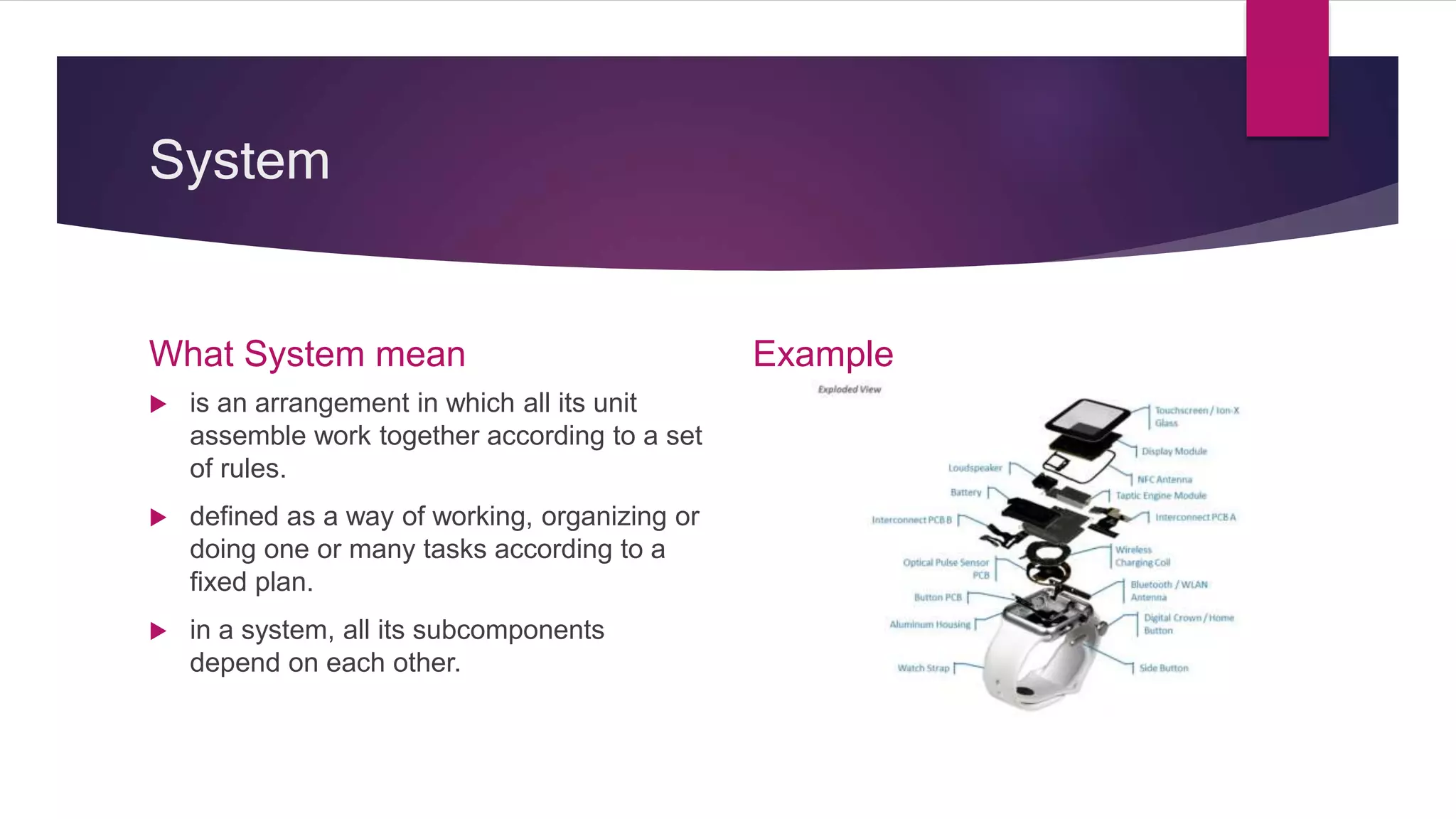
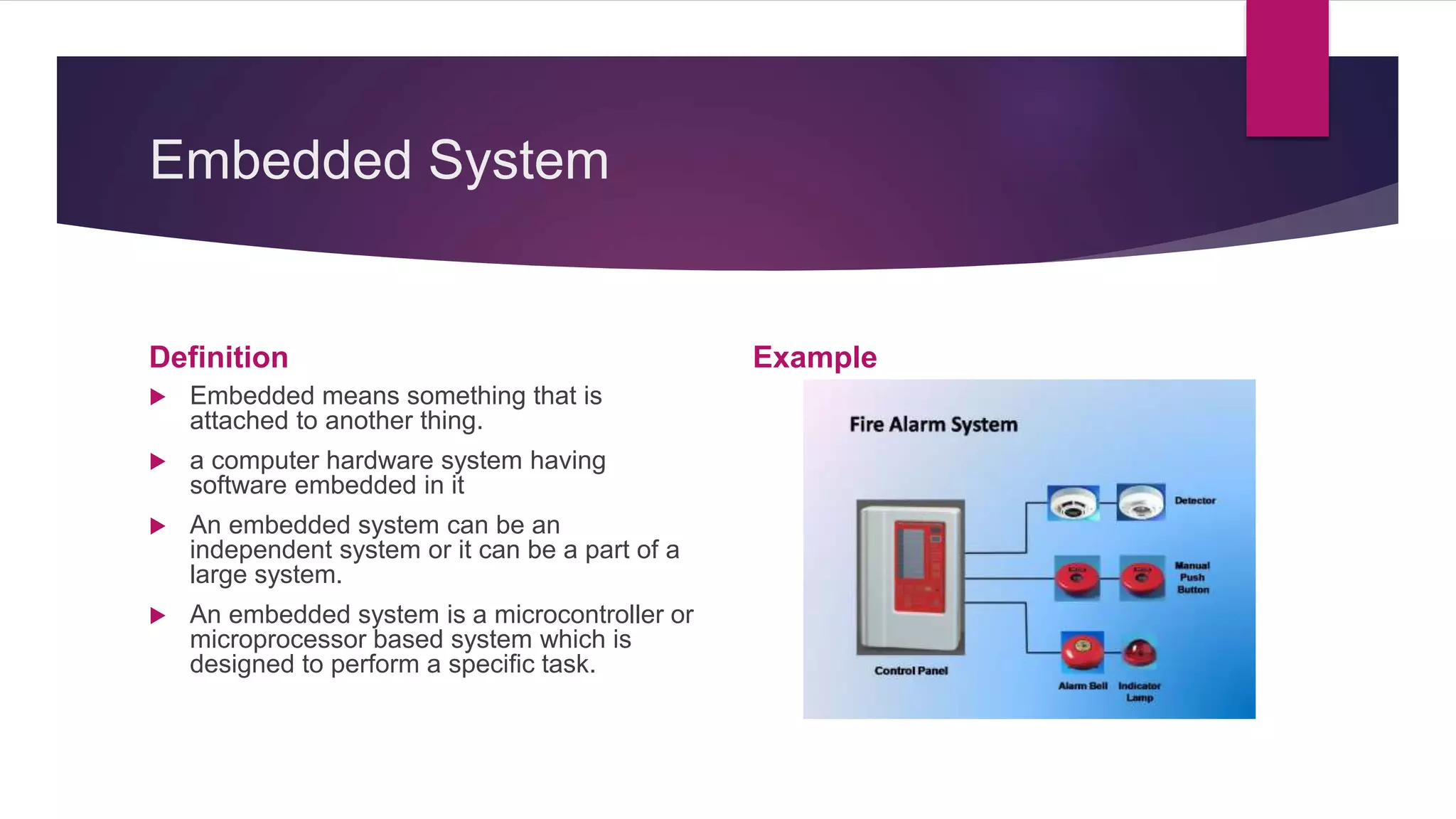
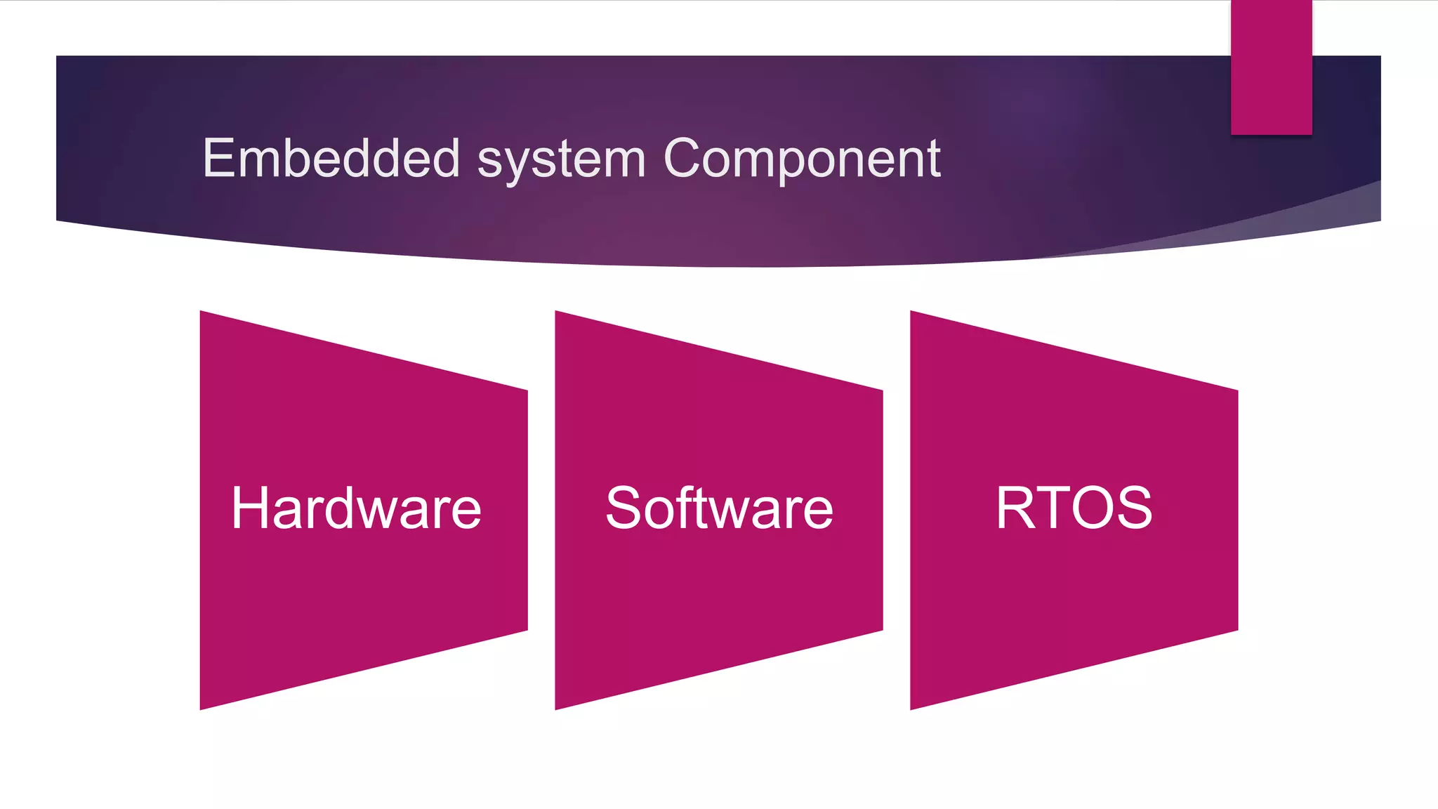
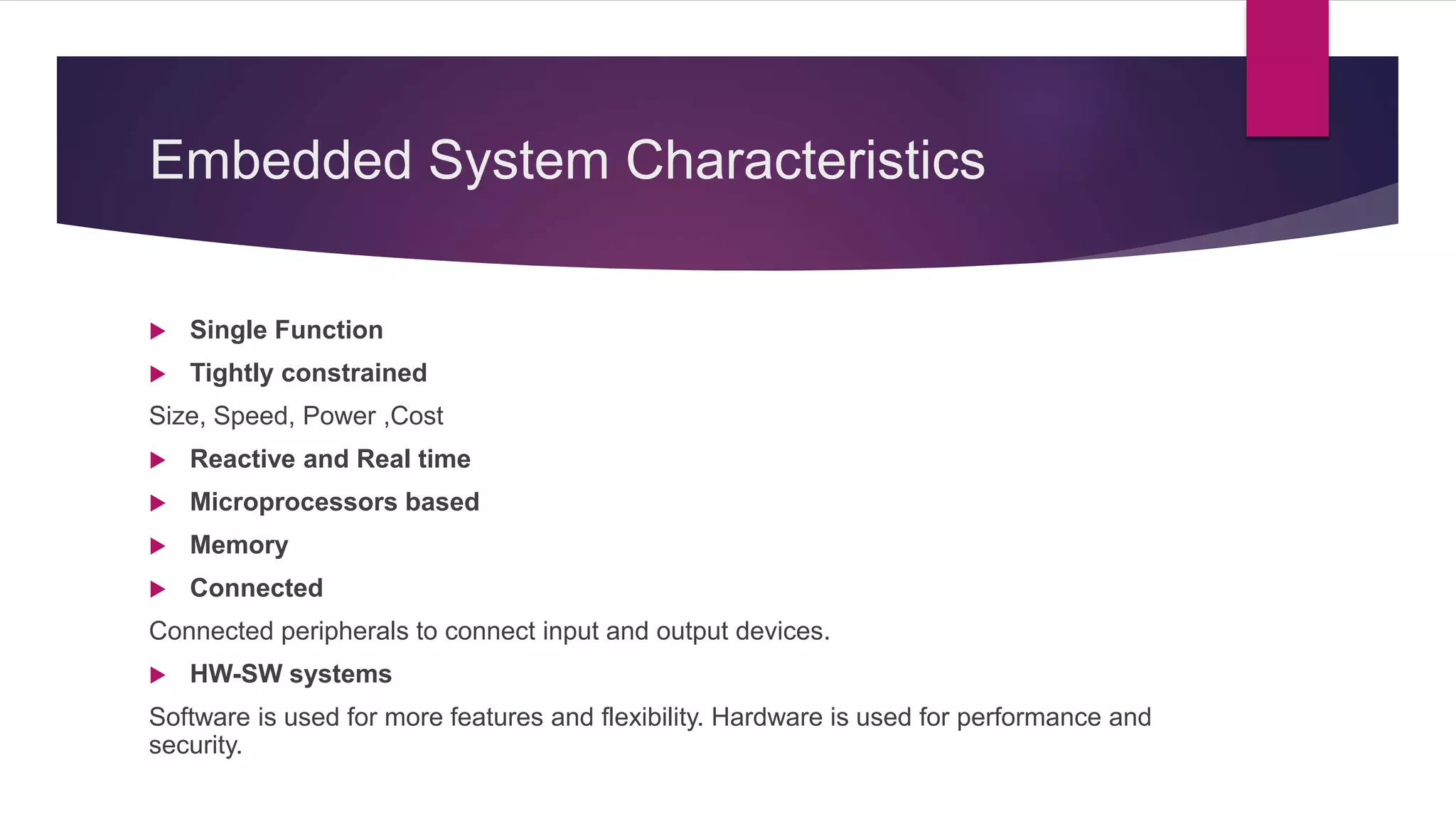
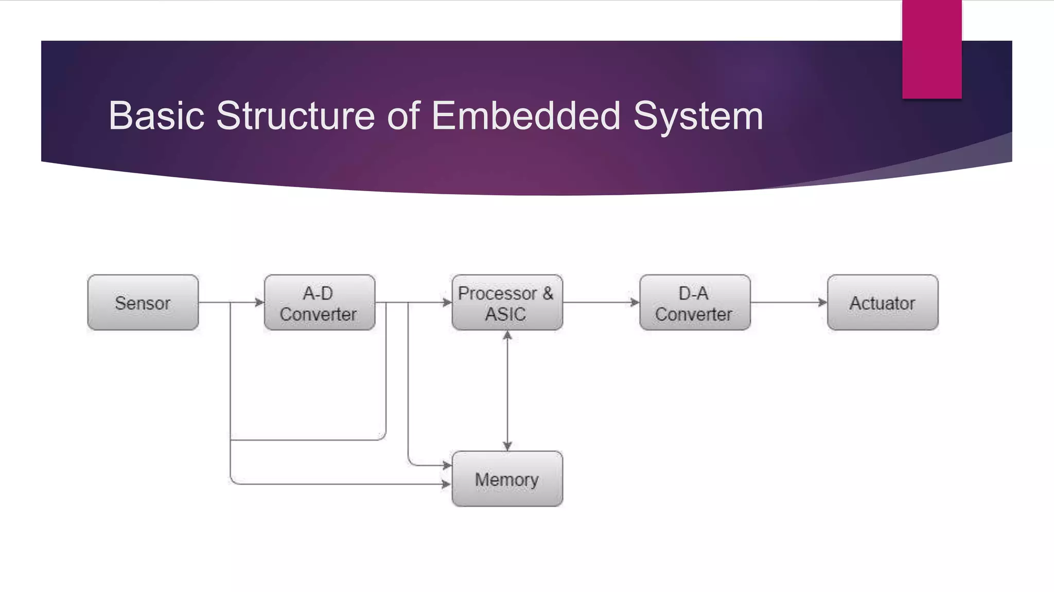
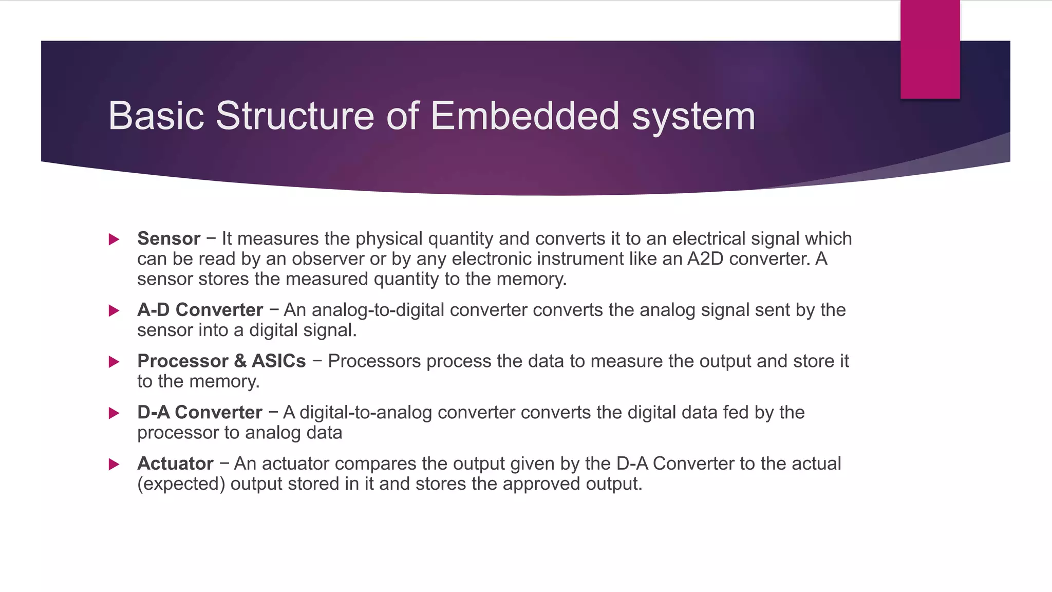
Introduction to embedded systems and their components like sensors, processors, and outputs.
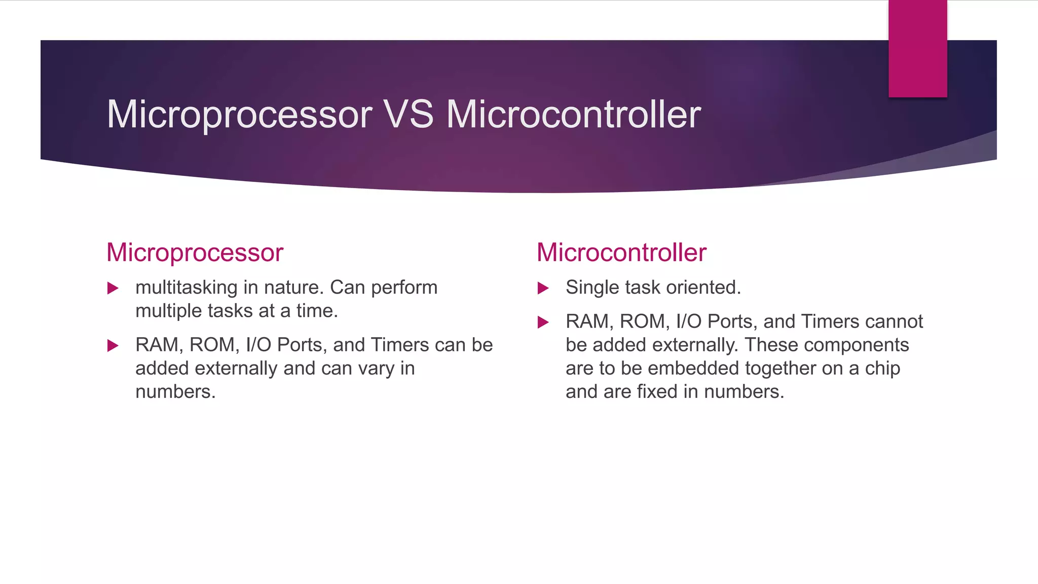
Differences between microprocessors (multitasking) and microcontrollers (single task oriented).
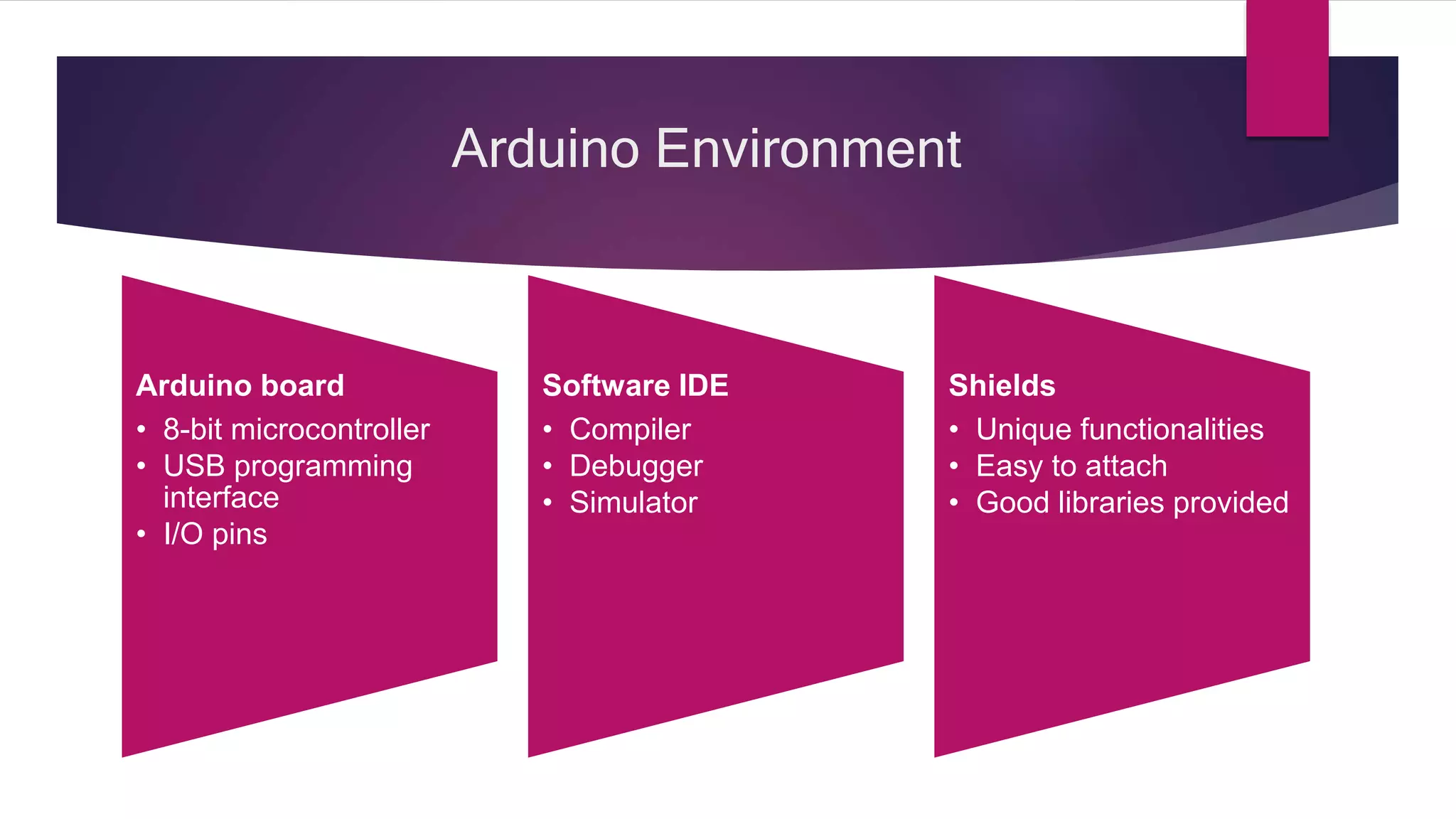
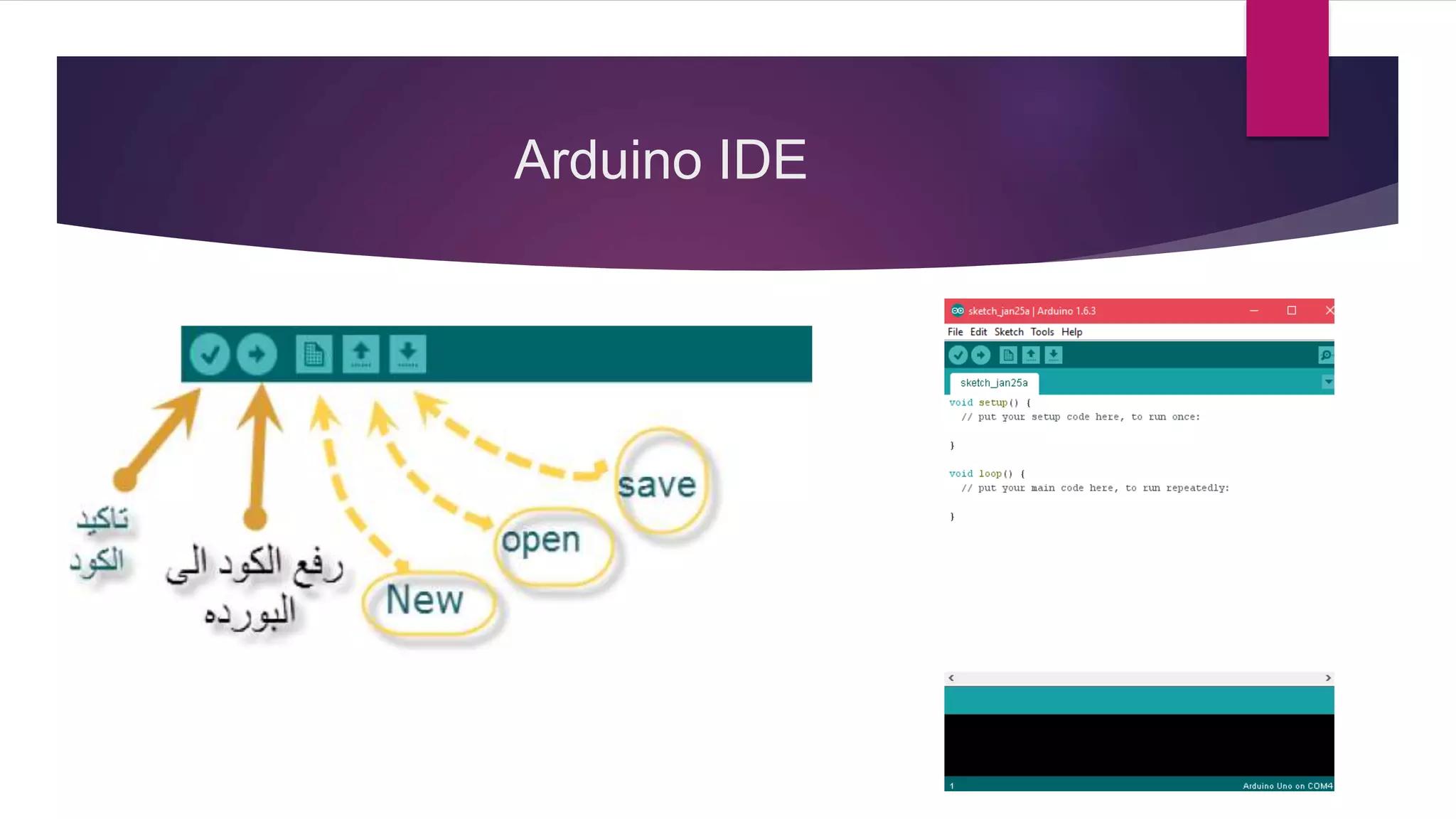
Overview of Arduino environment including the board, software IDE, capabilities, and key components.
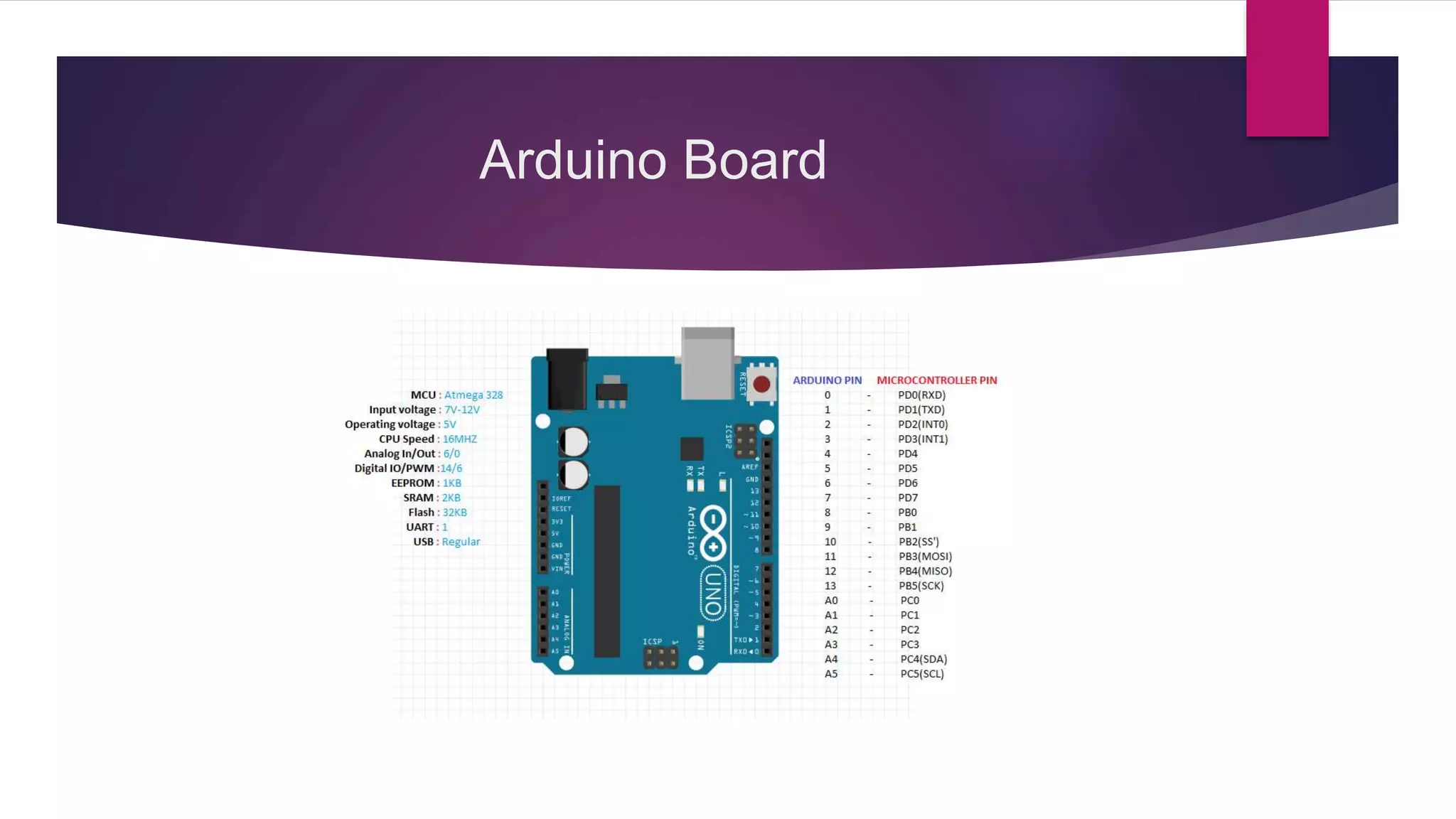
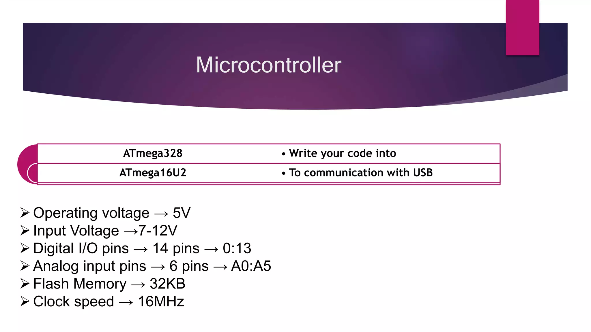
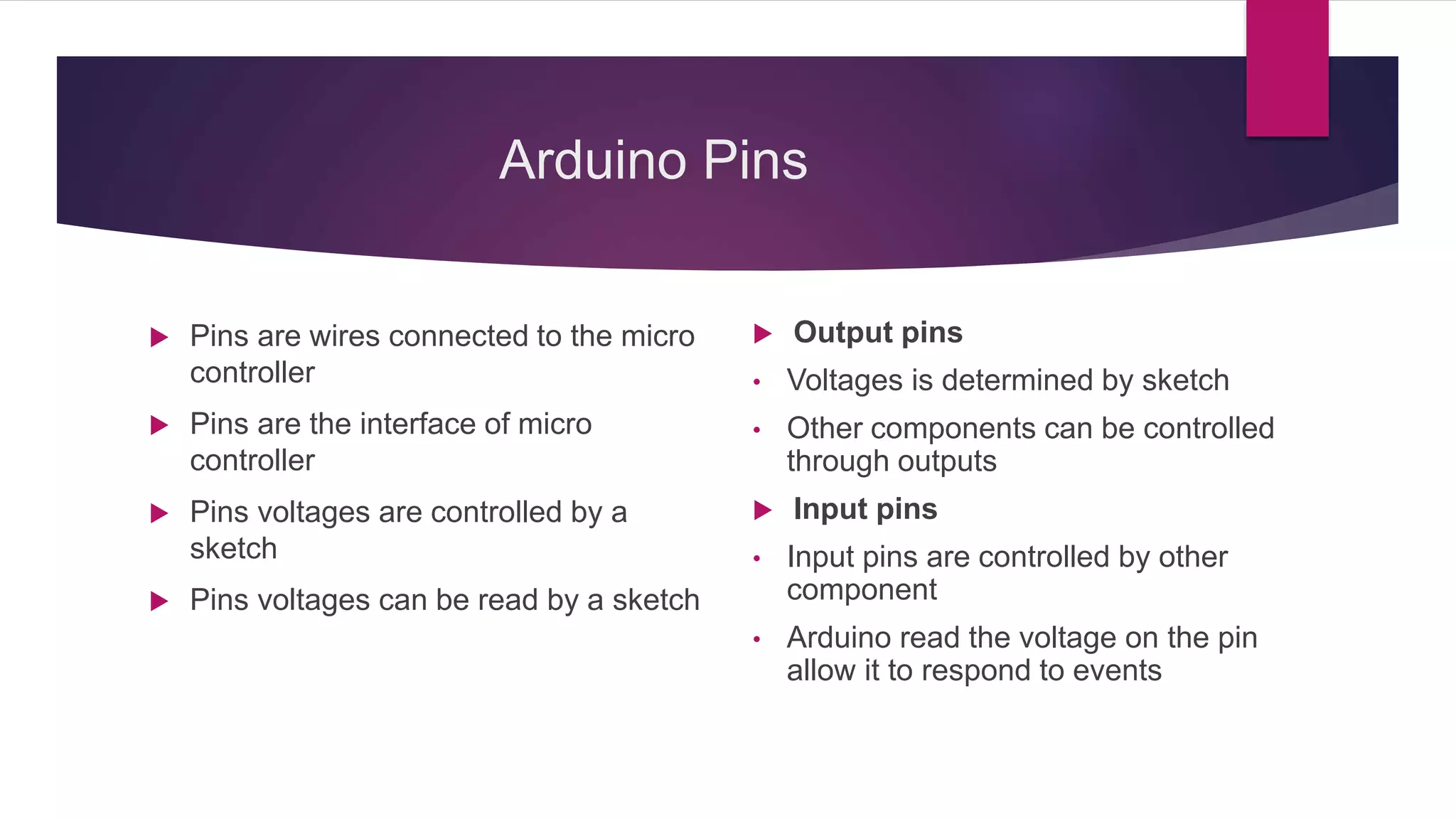
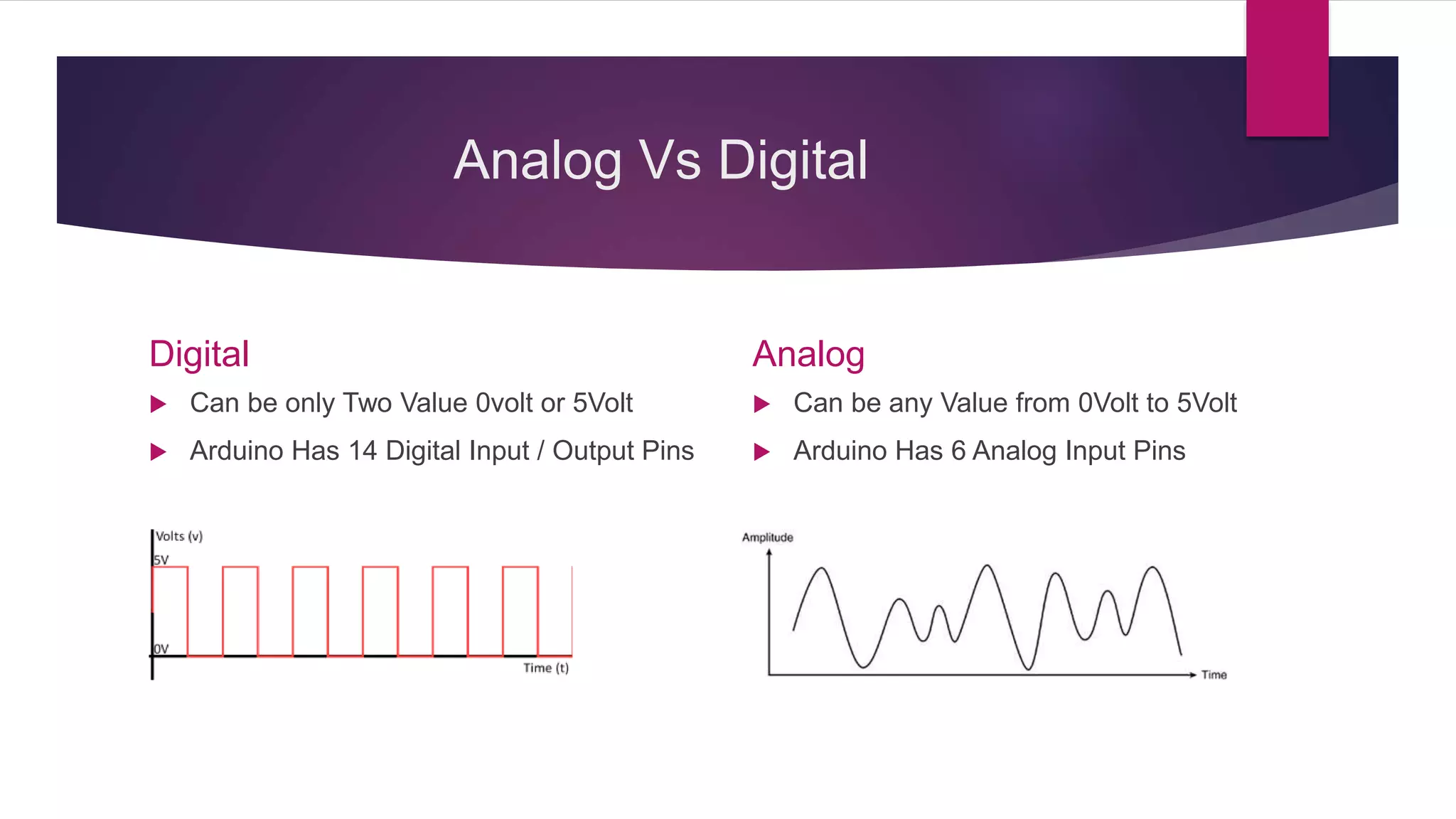
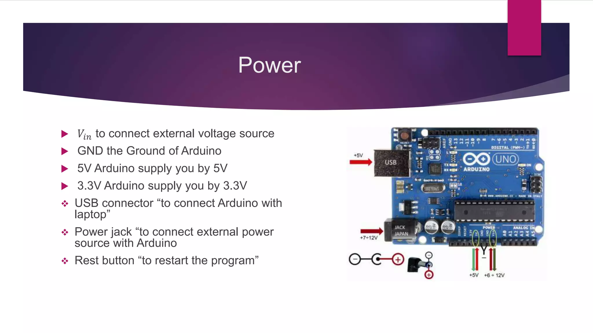
Details on Arduino pins, their functions, and power supply connections.
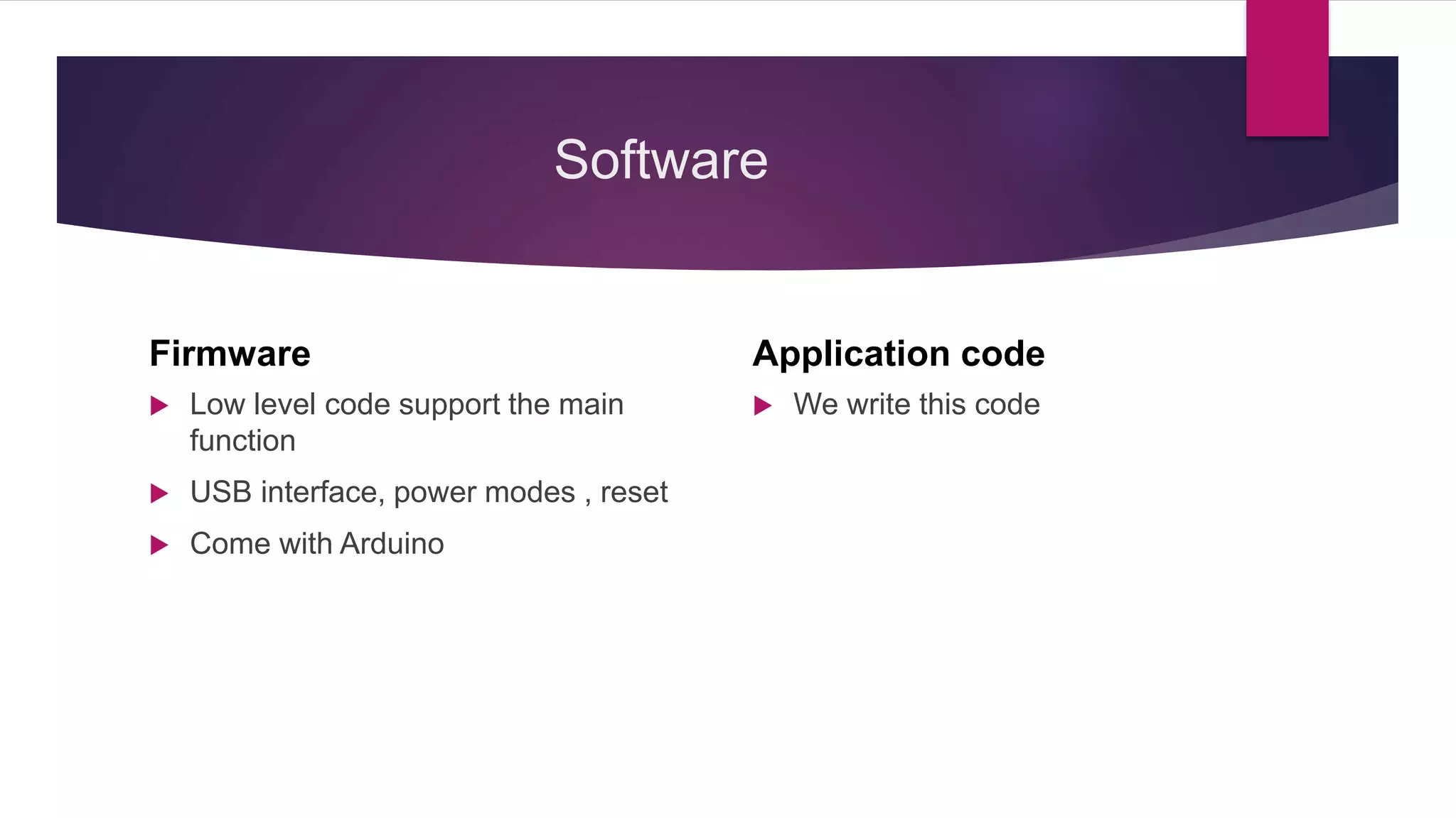
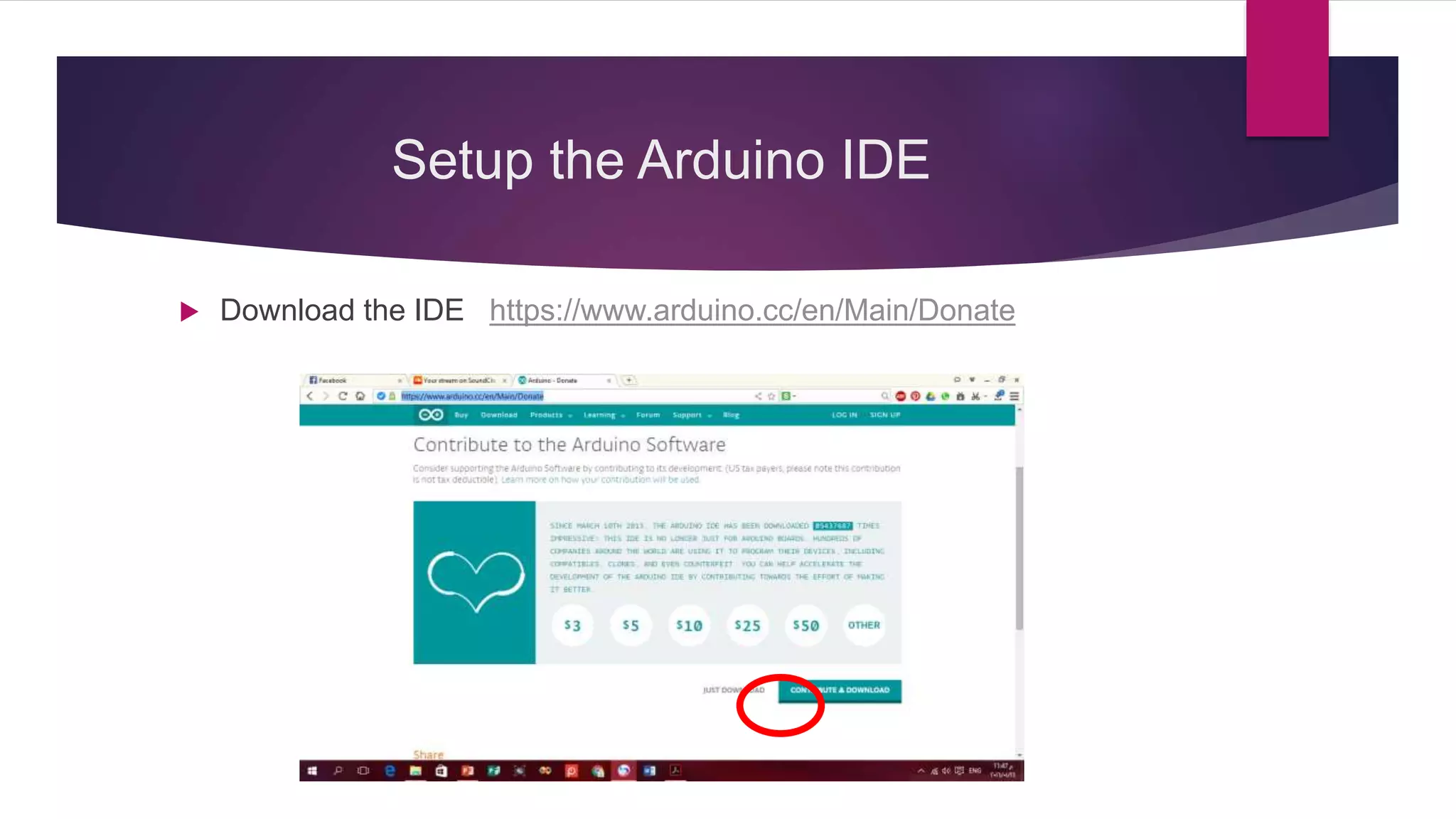
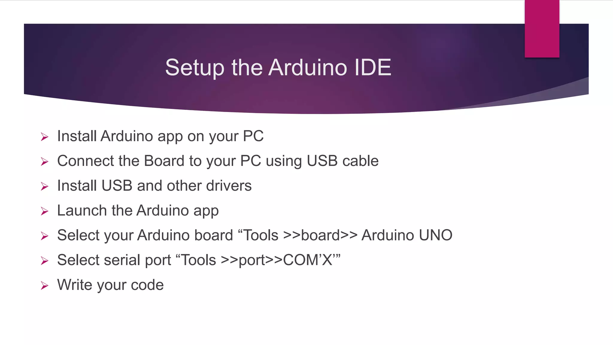
Introduction to Arduino firmware and application code along with software setup instructions.
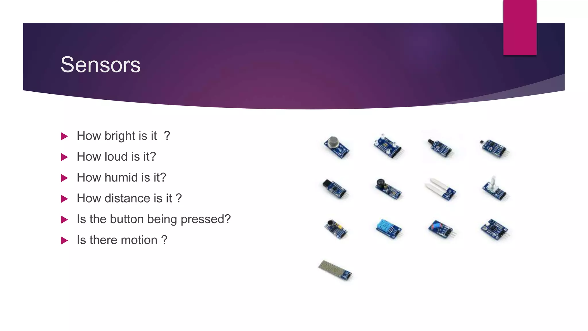
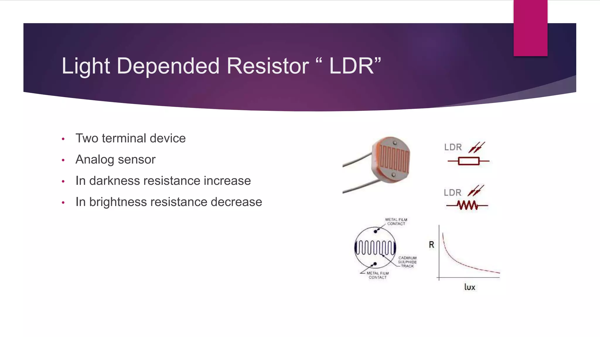
Discussion on various sensors, their functions, and how they capture environmental data.
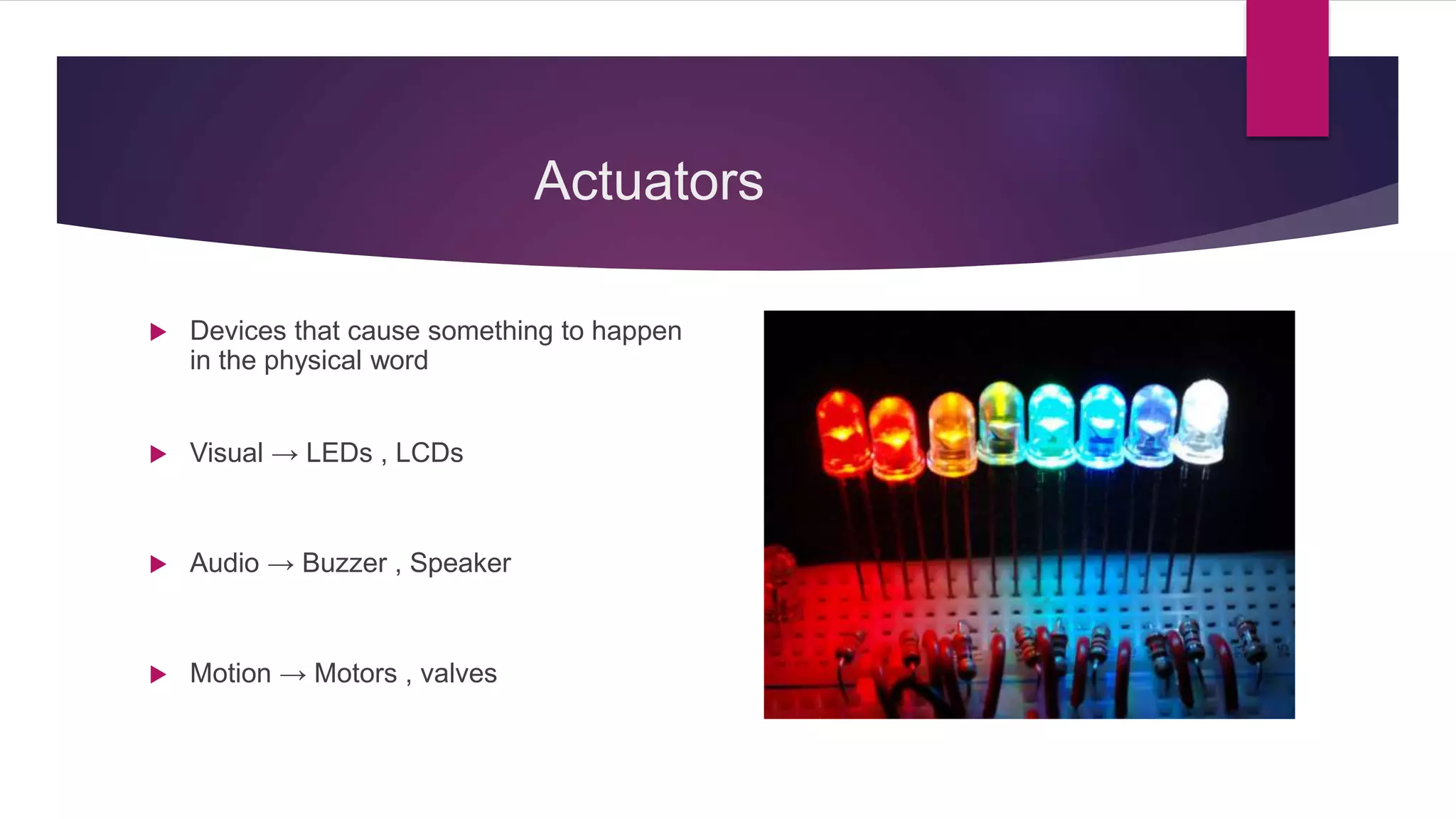
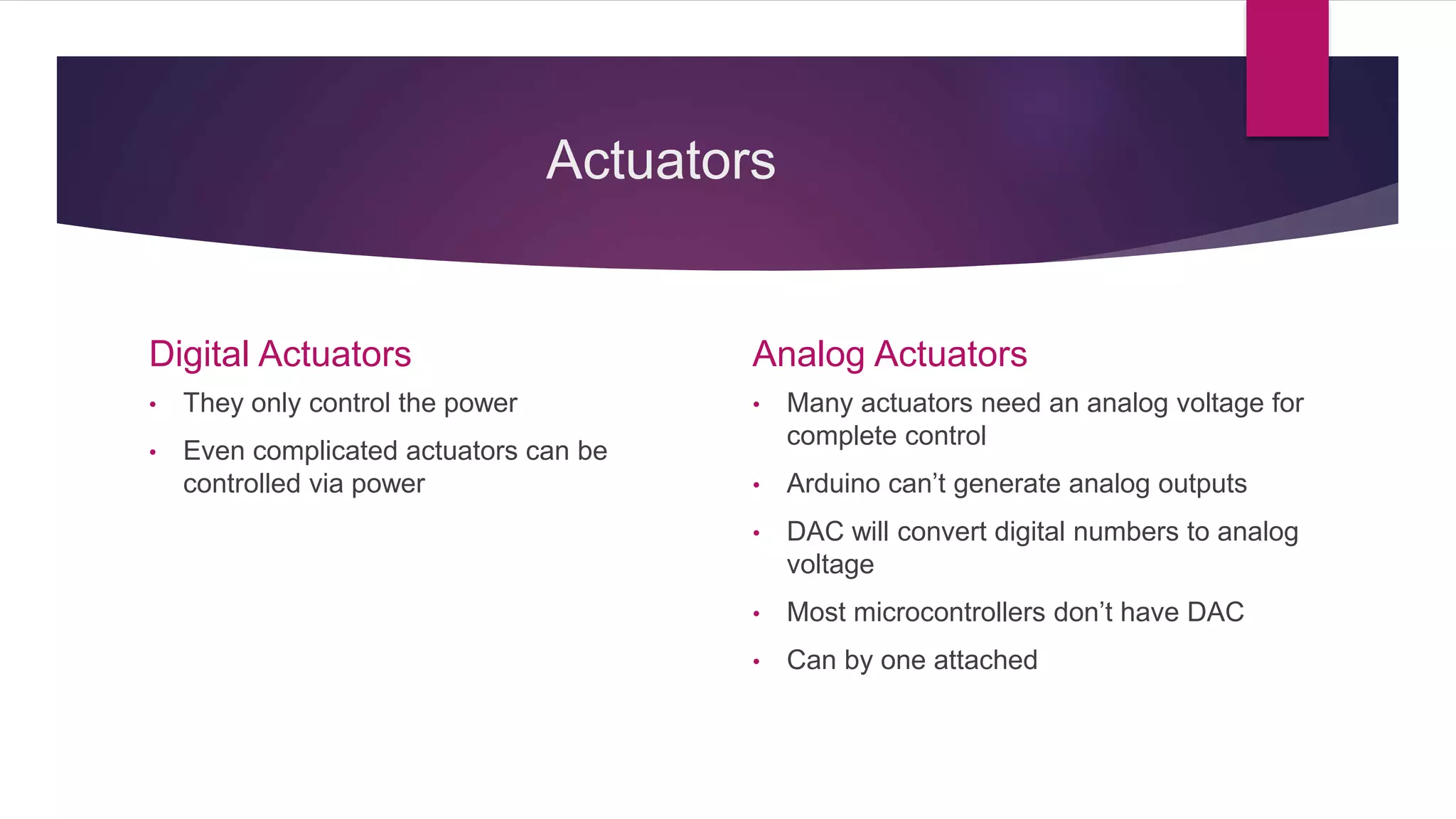
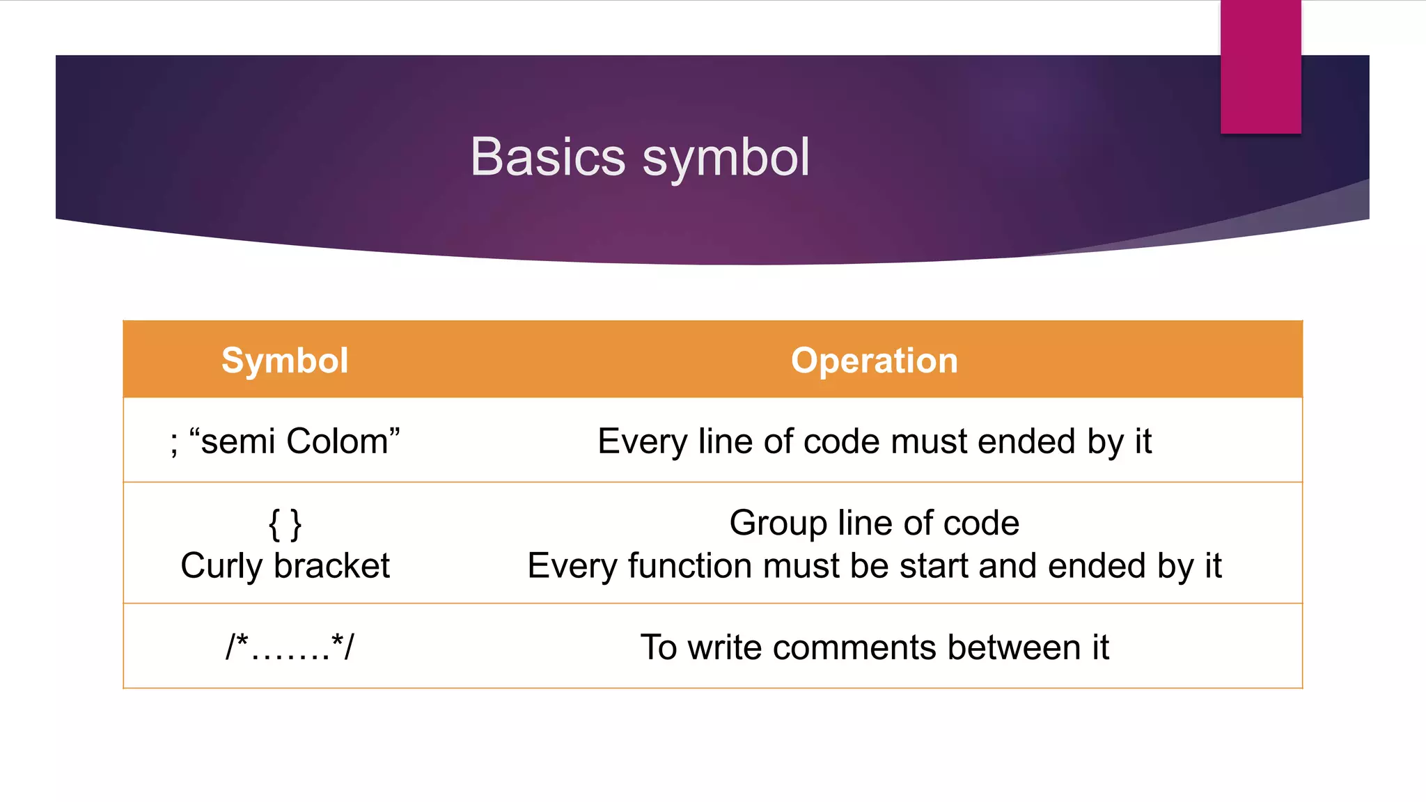
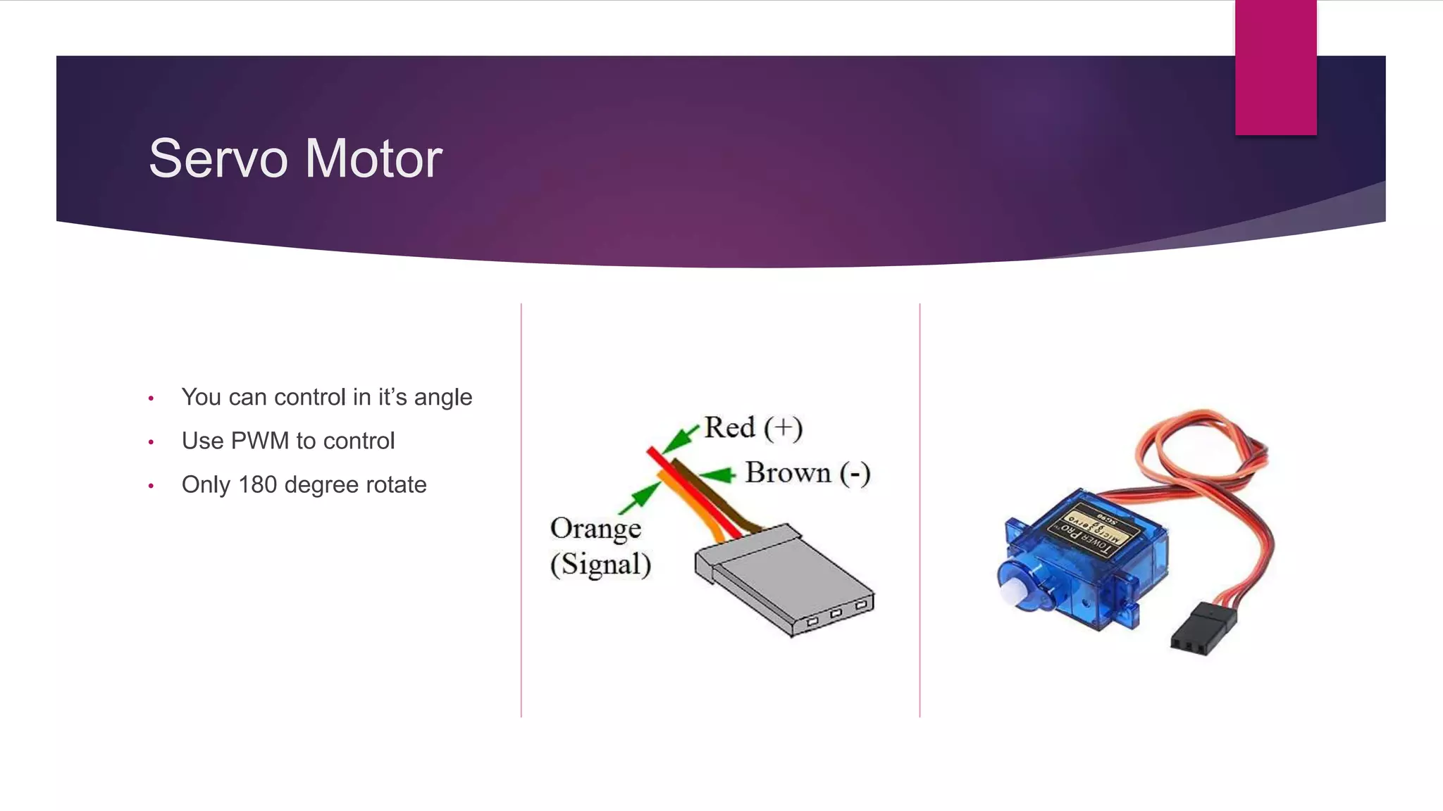
Explanation of actuators, their types, and how they interact with Arduino.Introduction to programming concepts in Arduino including functions, symbols, and control statements.
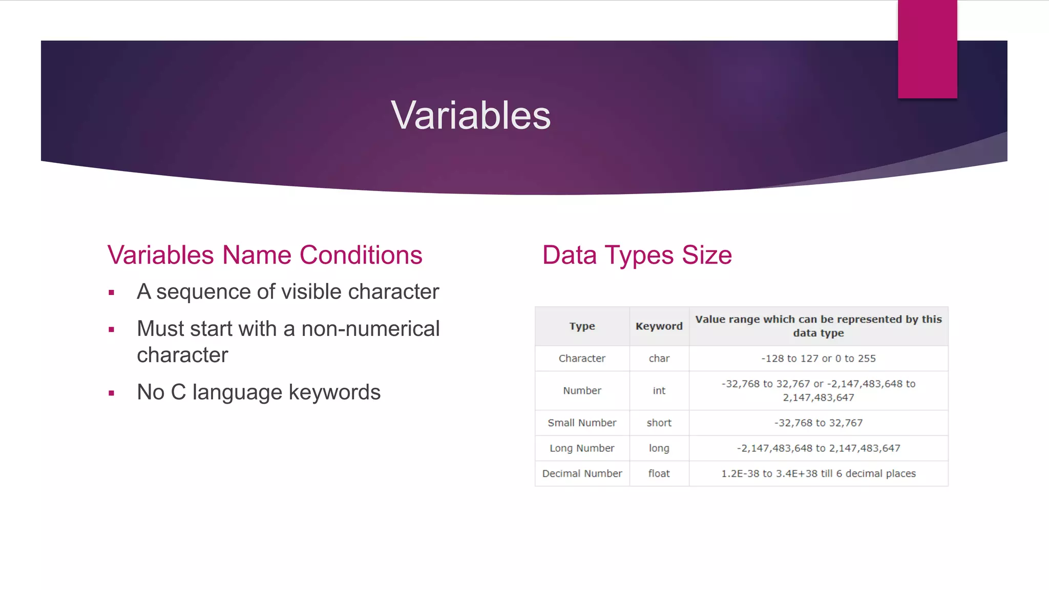
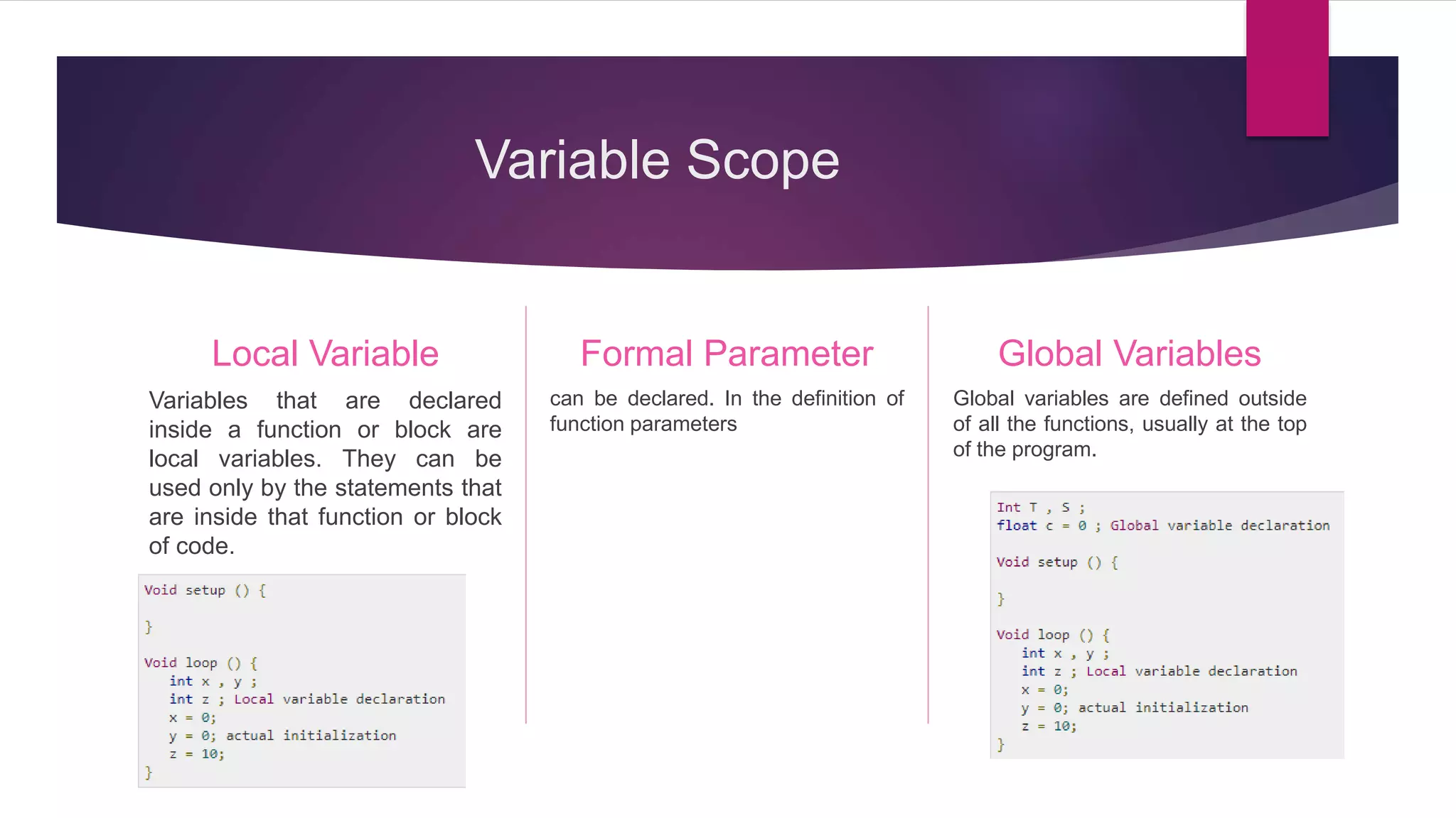
Discussion on variable scope, types, and characteristics related to programming Arduino.
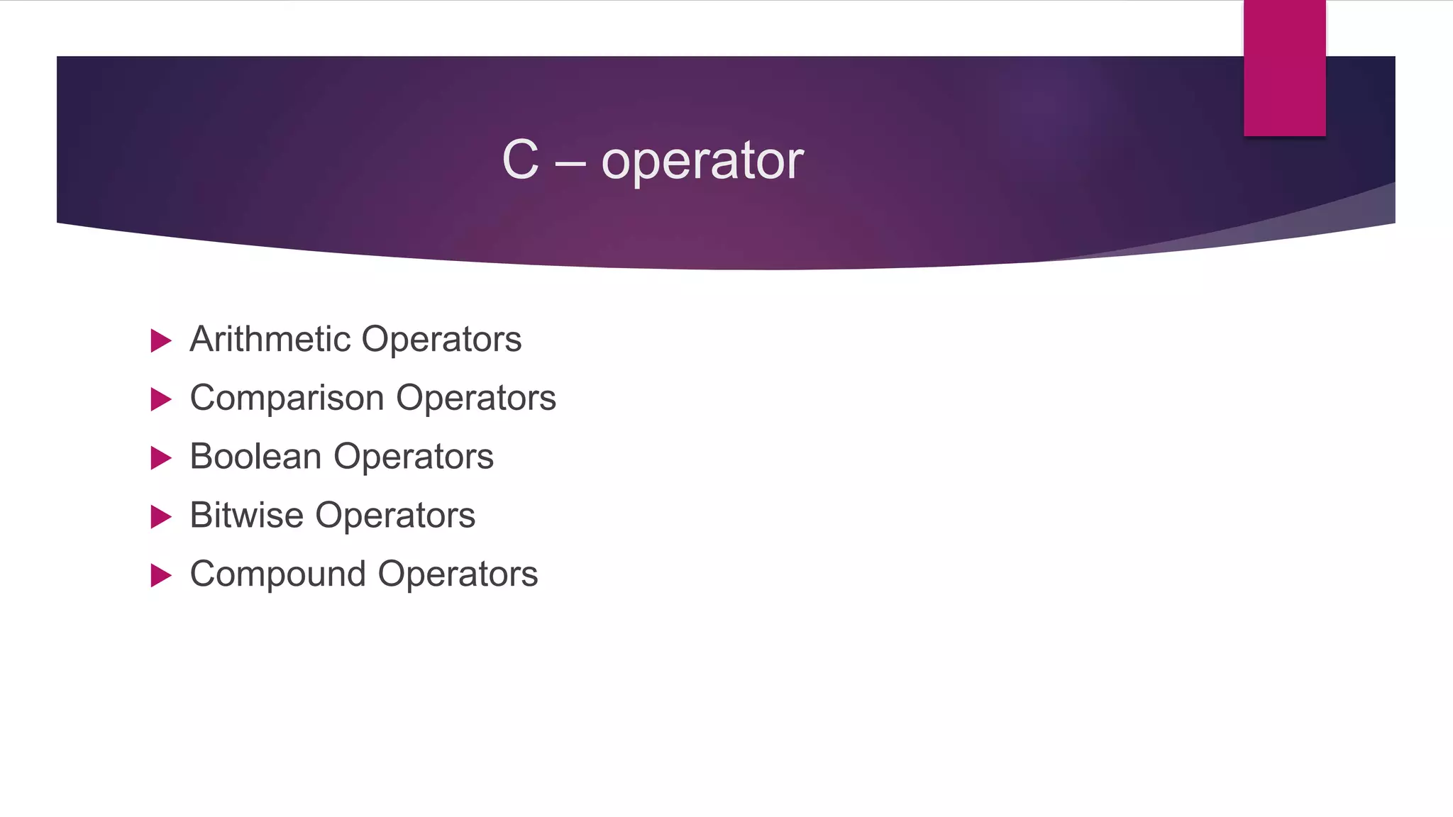
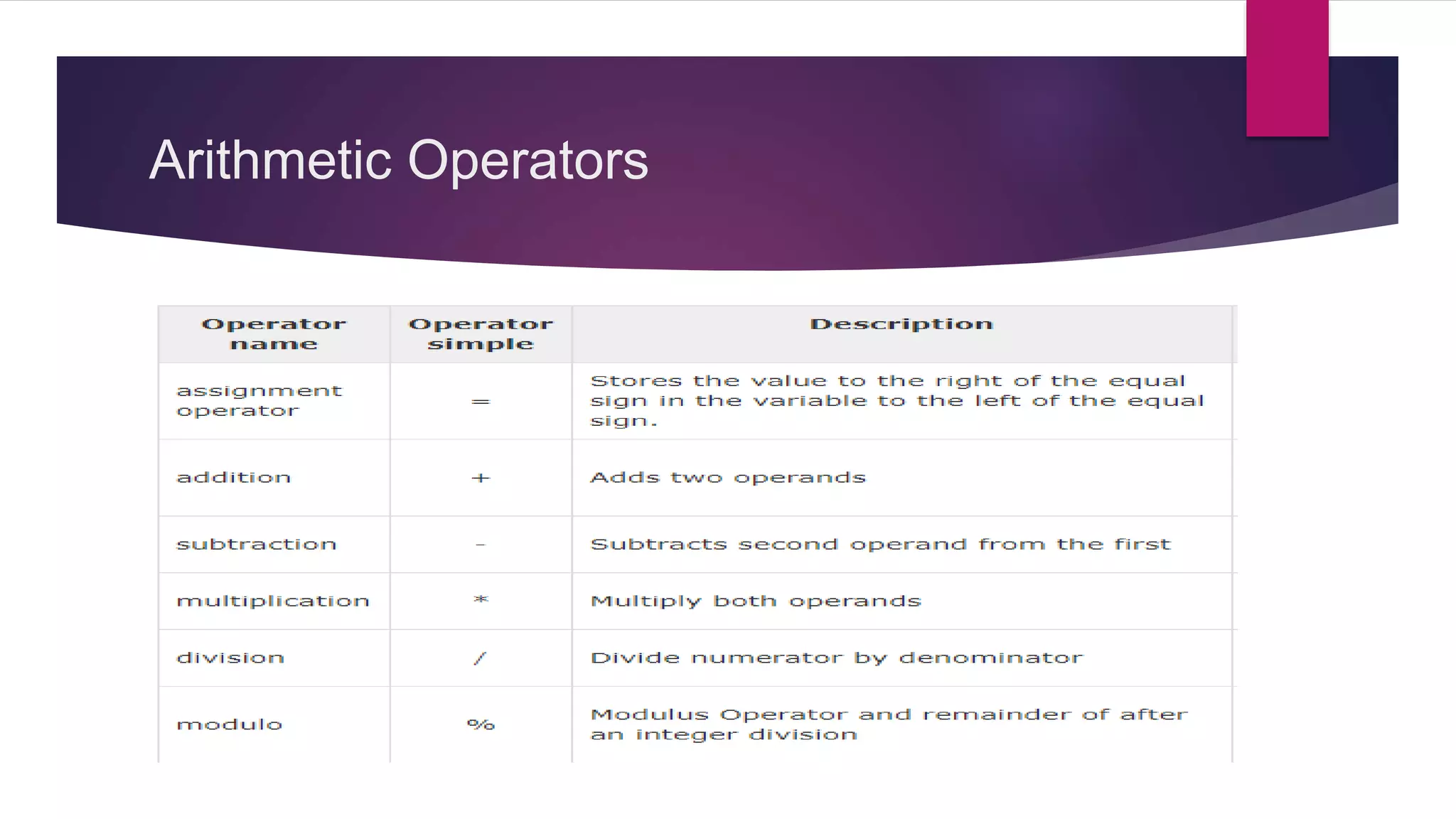
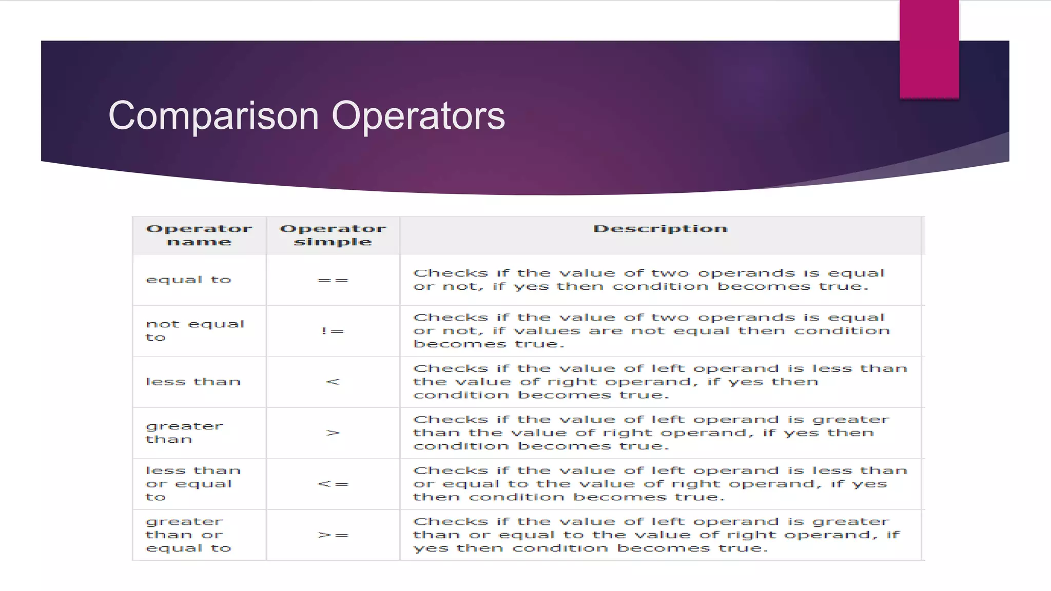
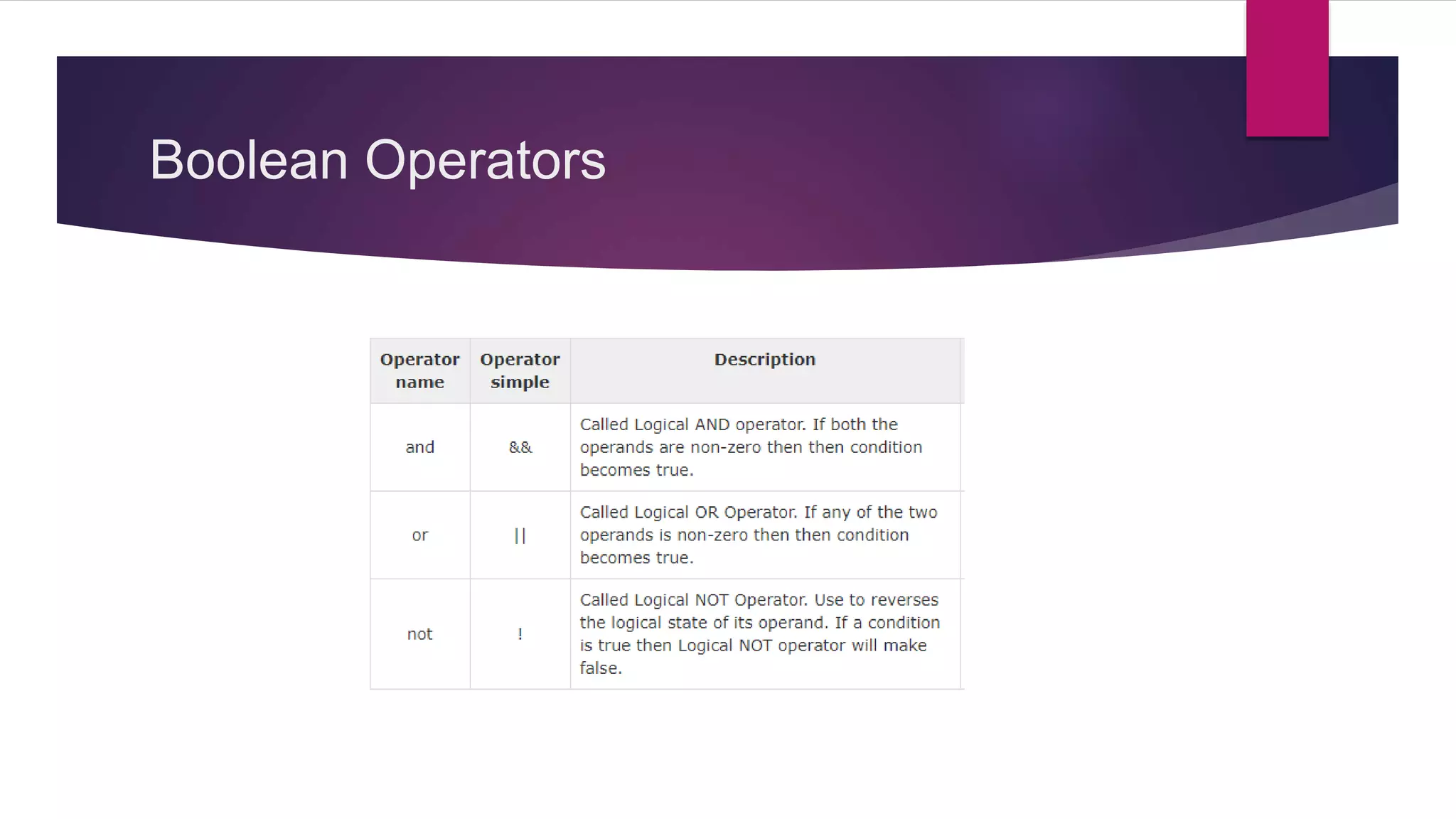
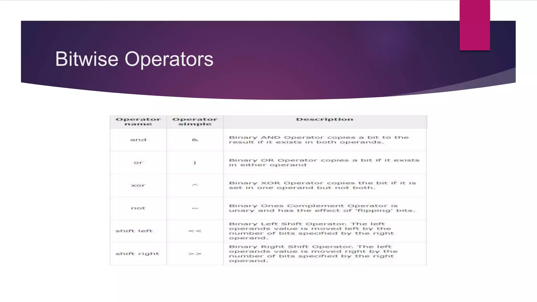
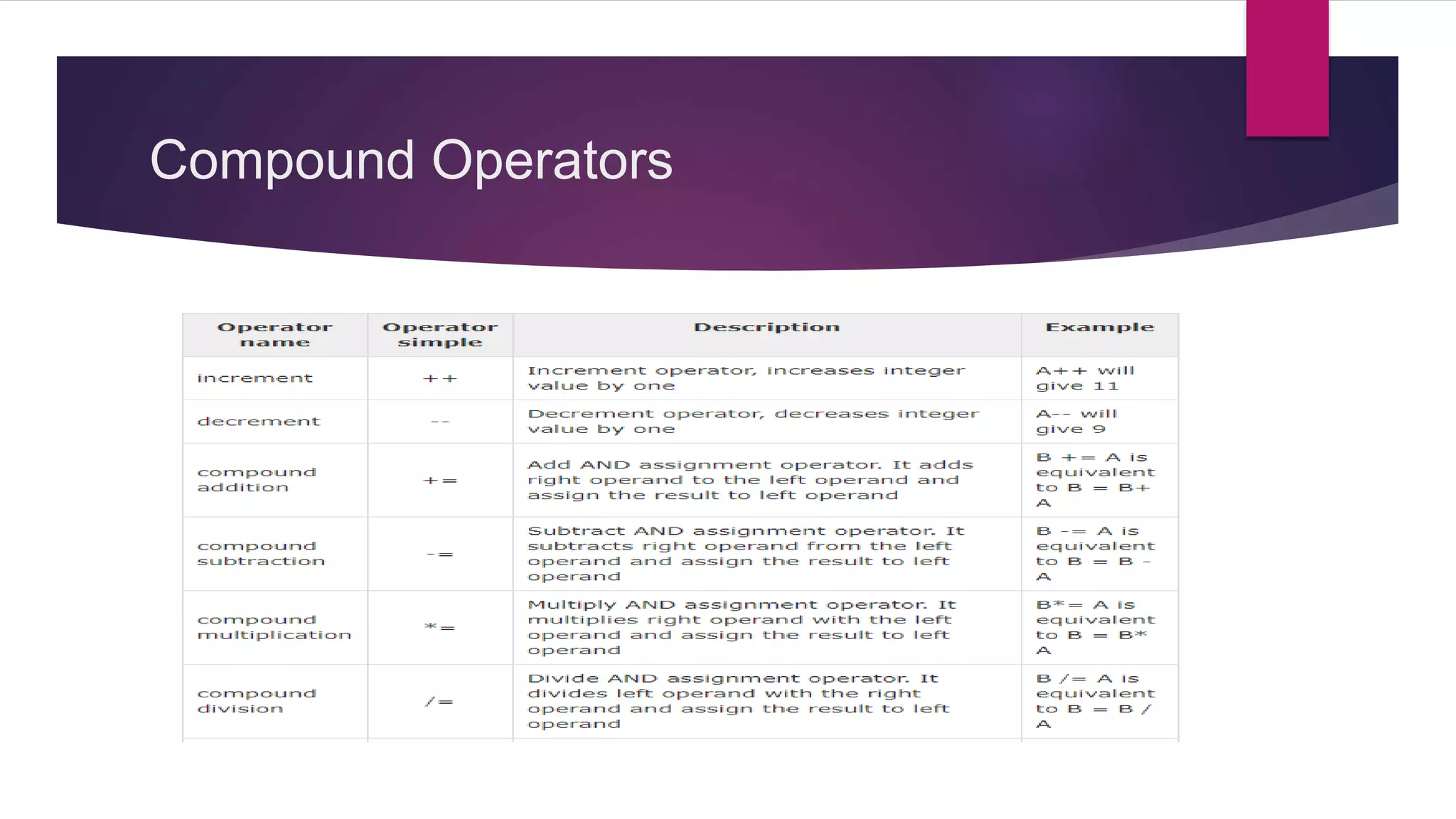
Different types of operators including arithmetic, comparison, boolean, bitwise, and compound.
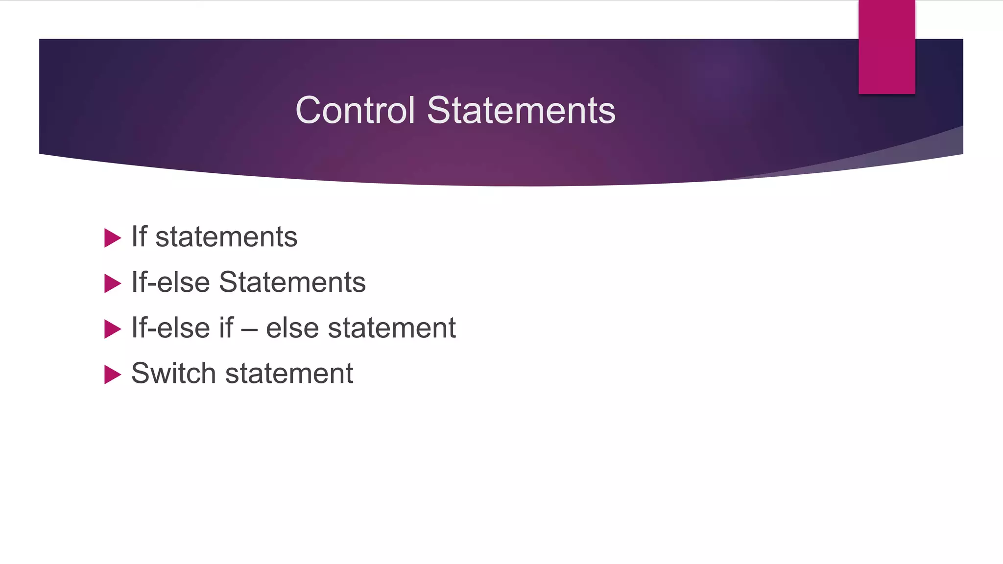
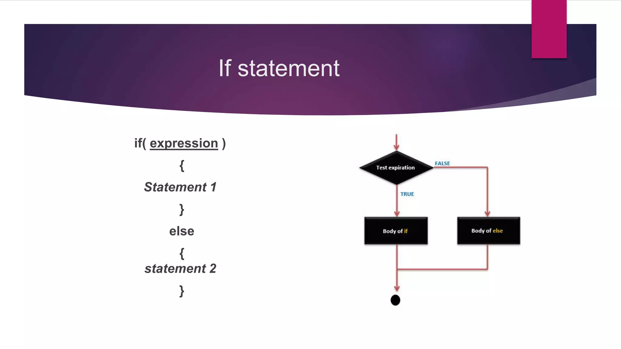
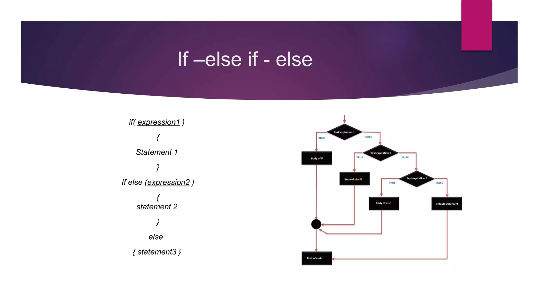
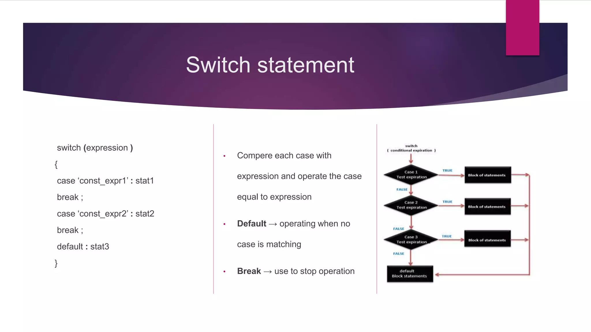
Control statements like if, switch, and corresponding programming structures.
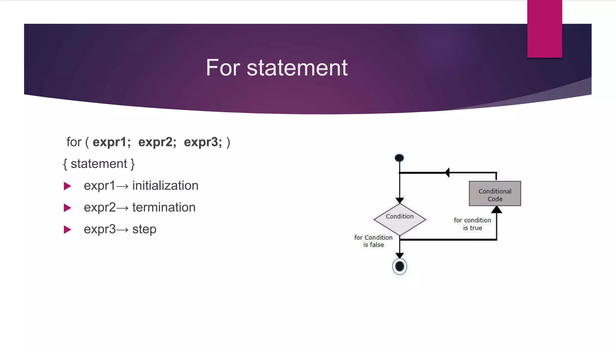
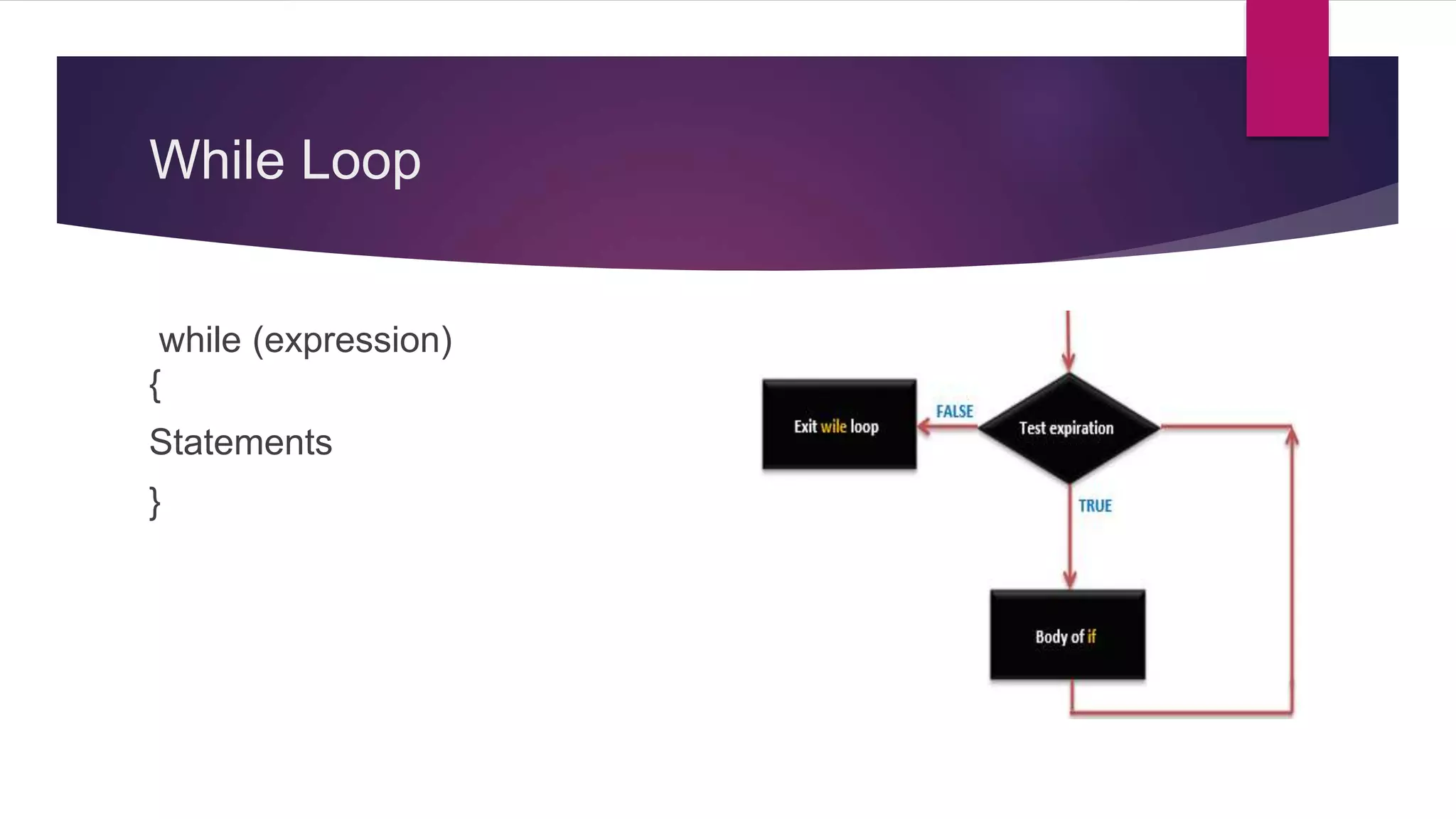
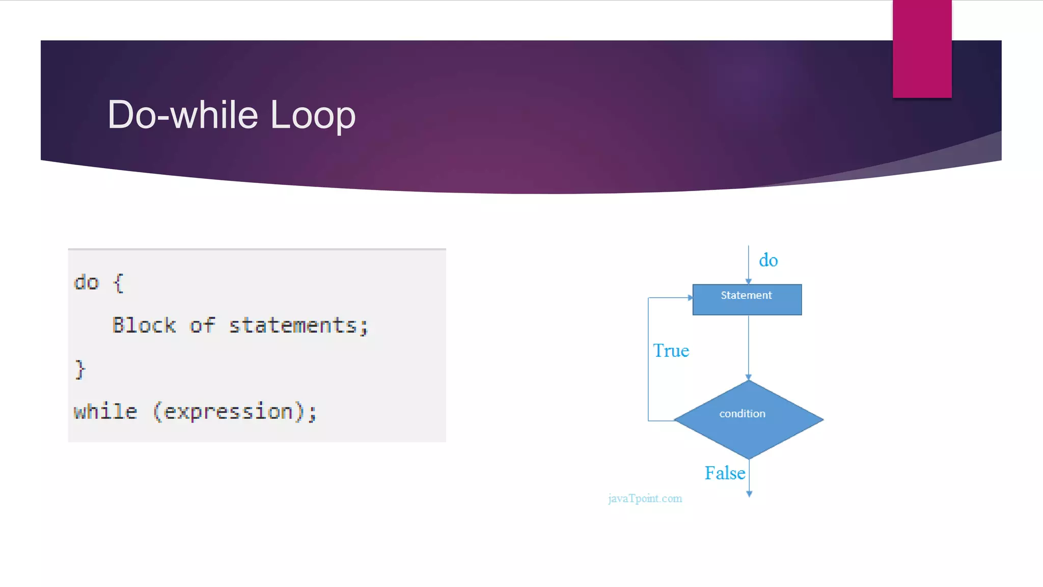
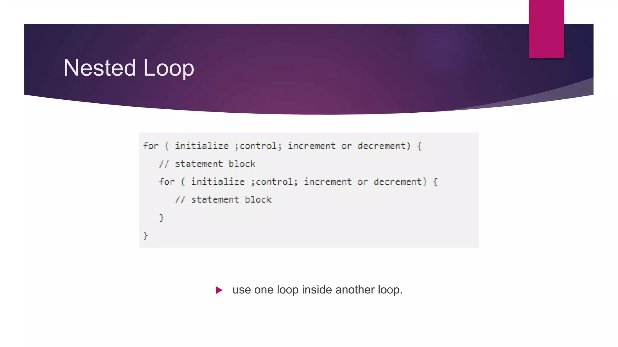
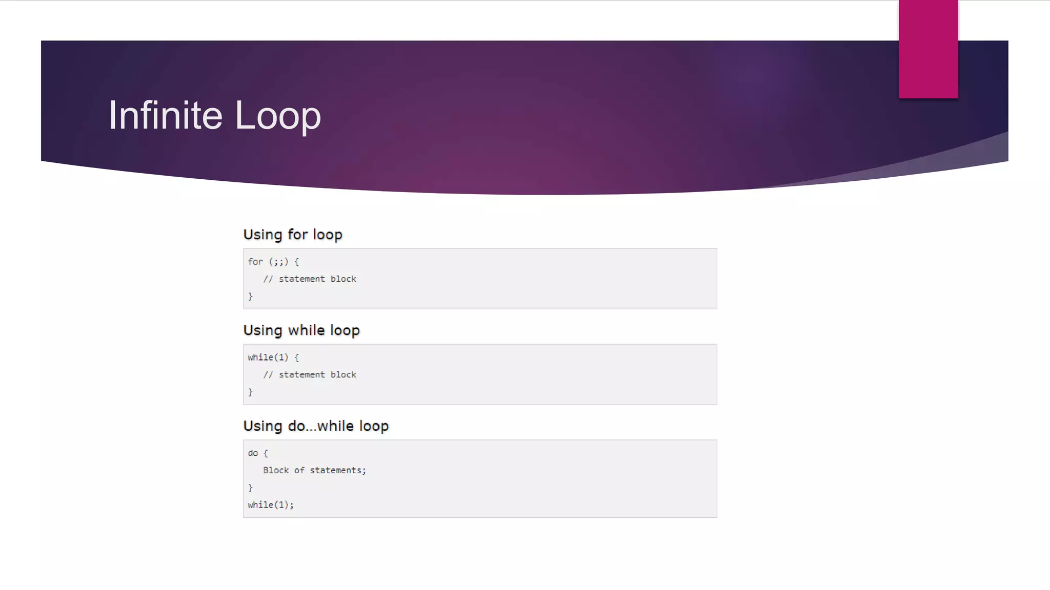
Varied loop structures including for, while, and nested loops for repetitive tasks.
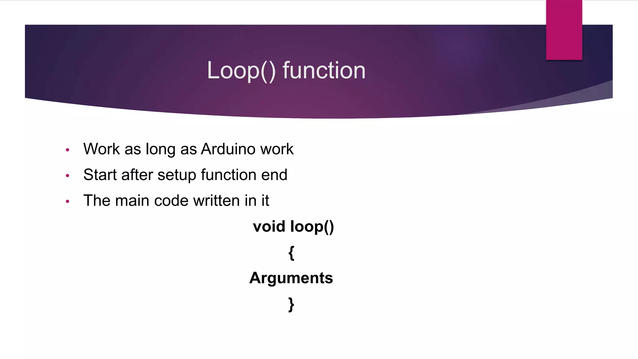
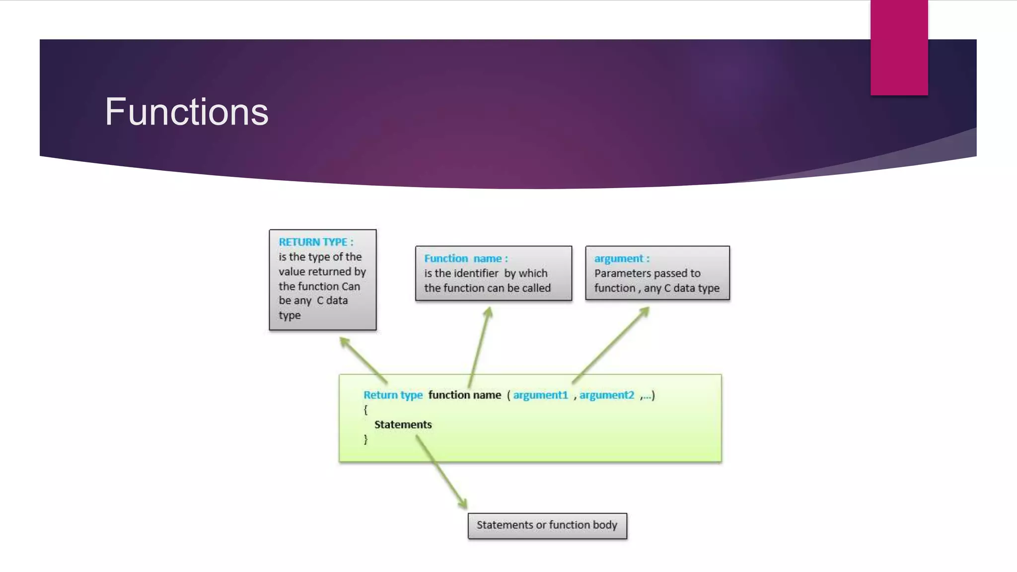
Overview of functions and how they are utilized in programming for Arduino.
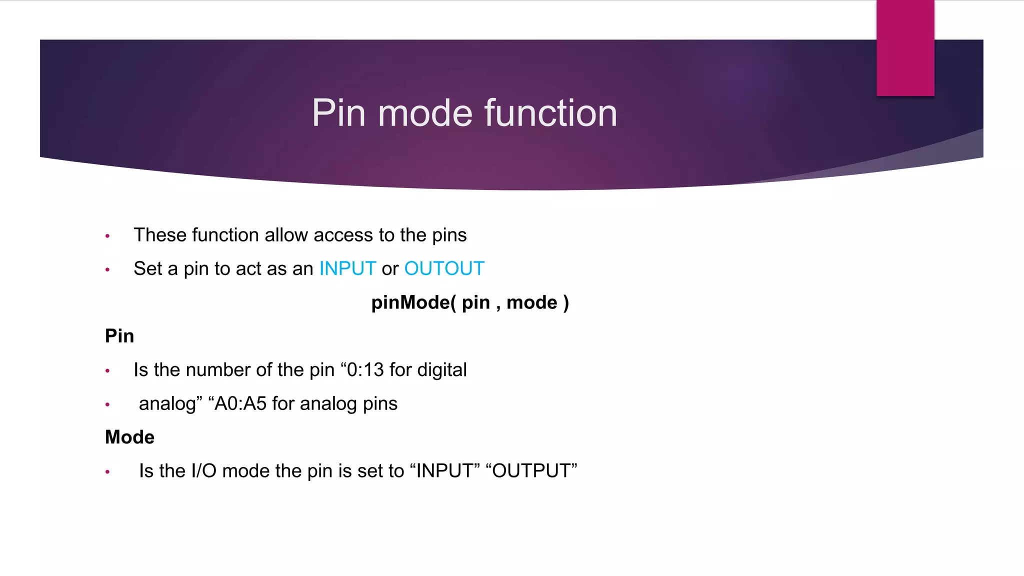
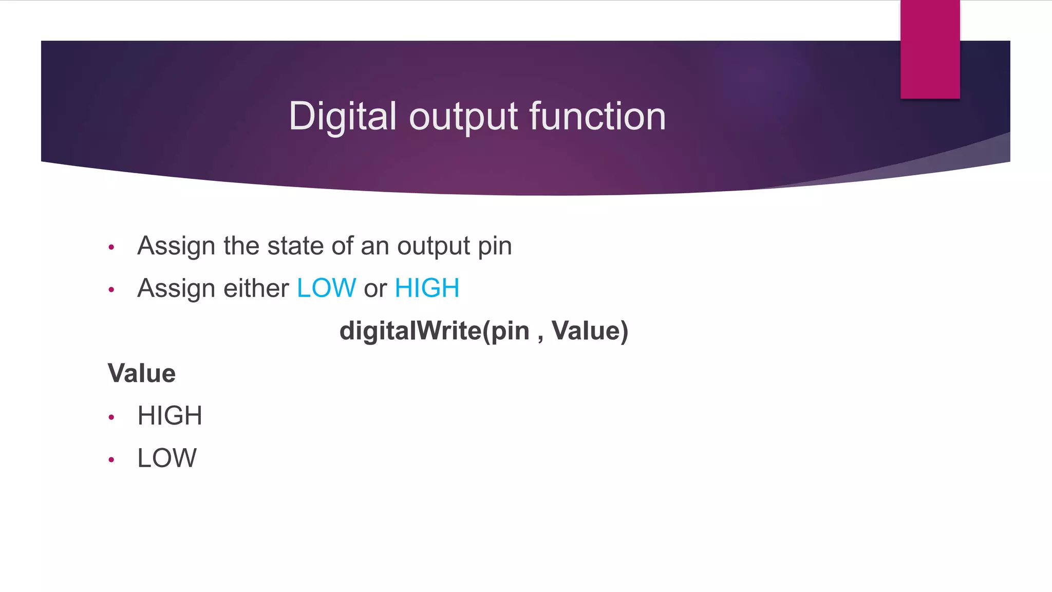
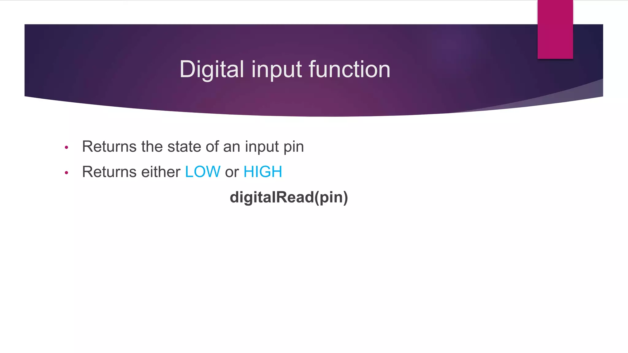
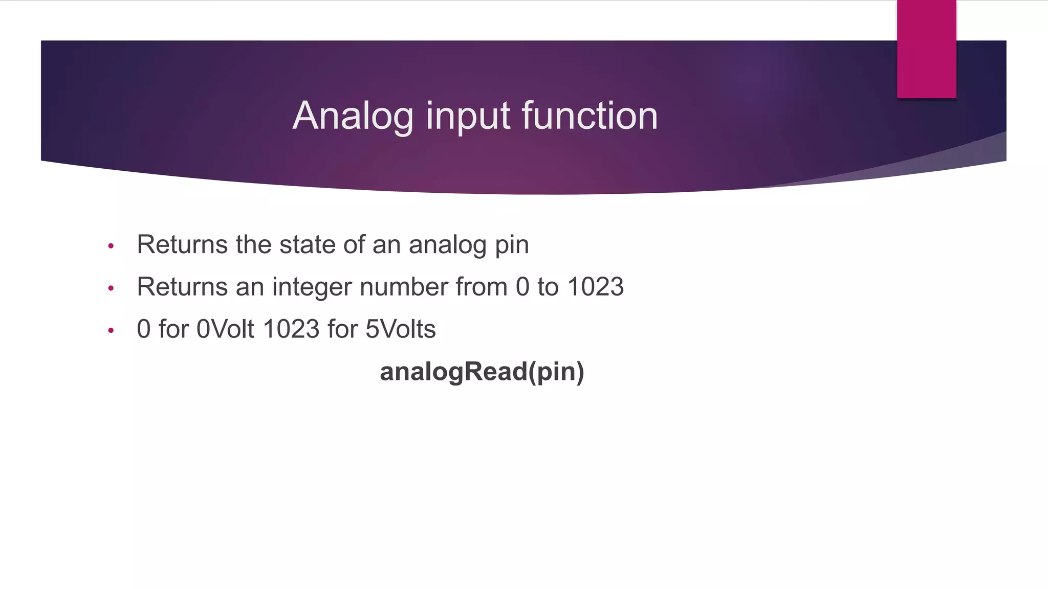
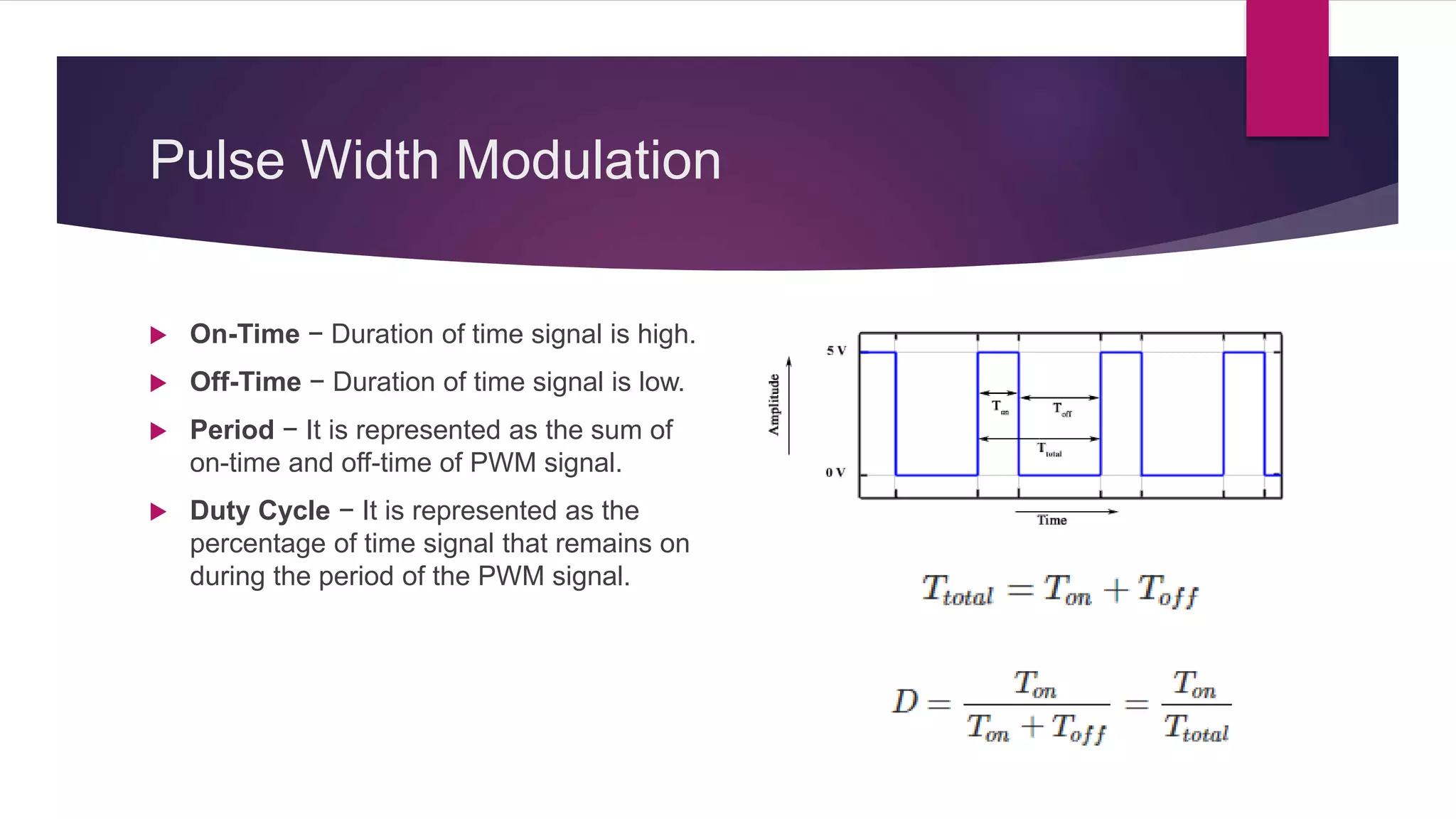
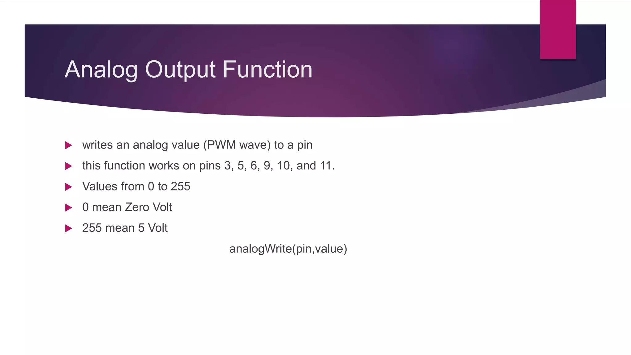
Pin mode, digital input/output, delay functions, and analog input/output descriptions.
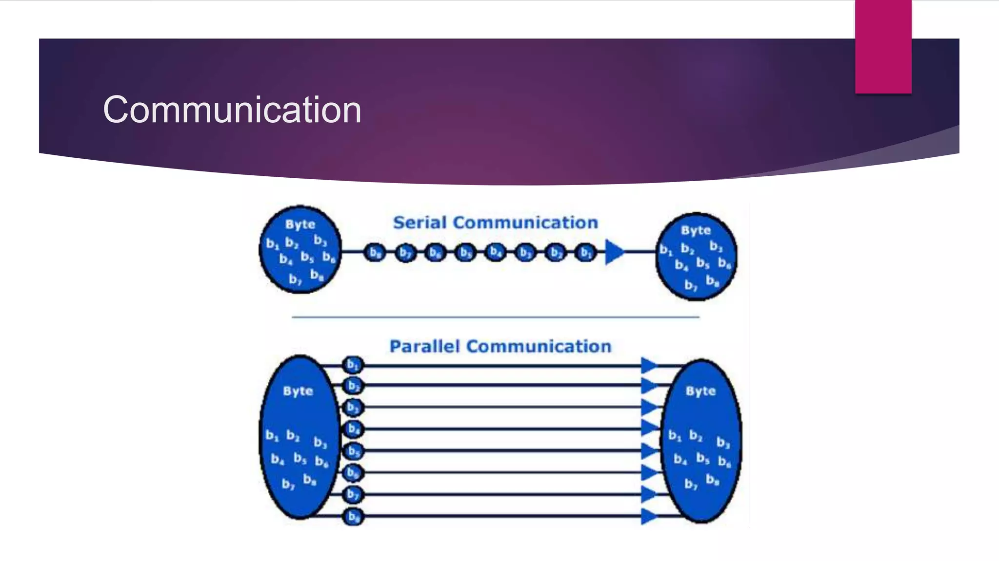
Introduction to serial communication for data transfer between Arduino and external devices.
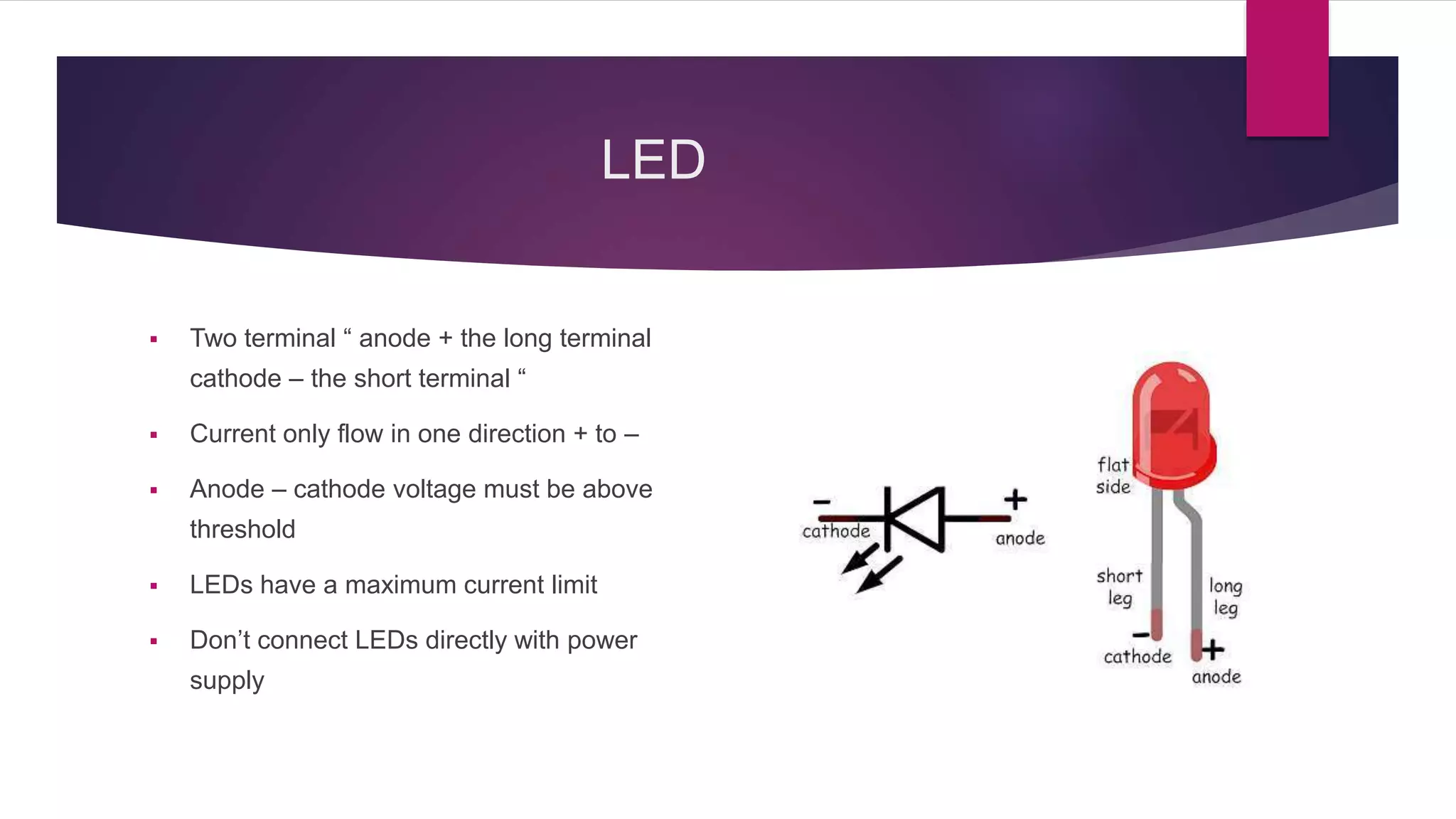
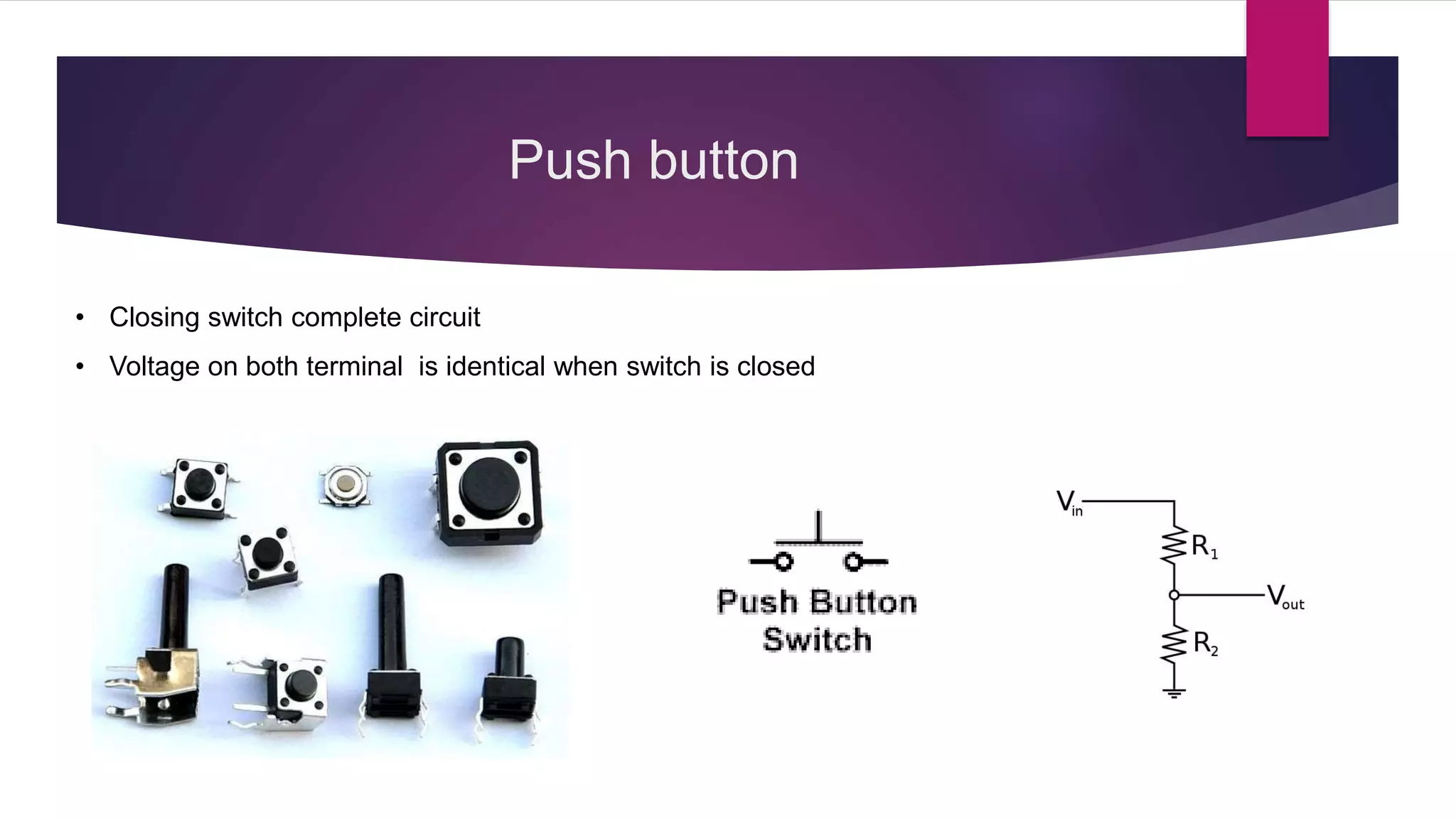
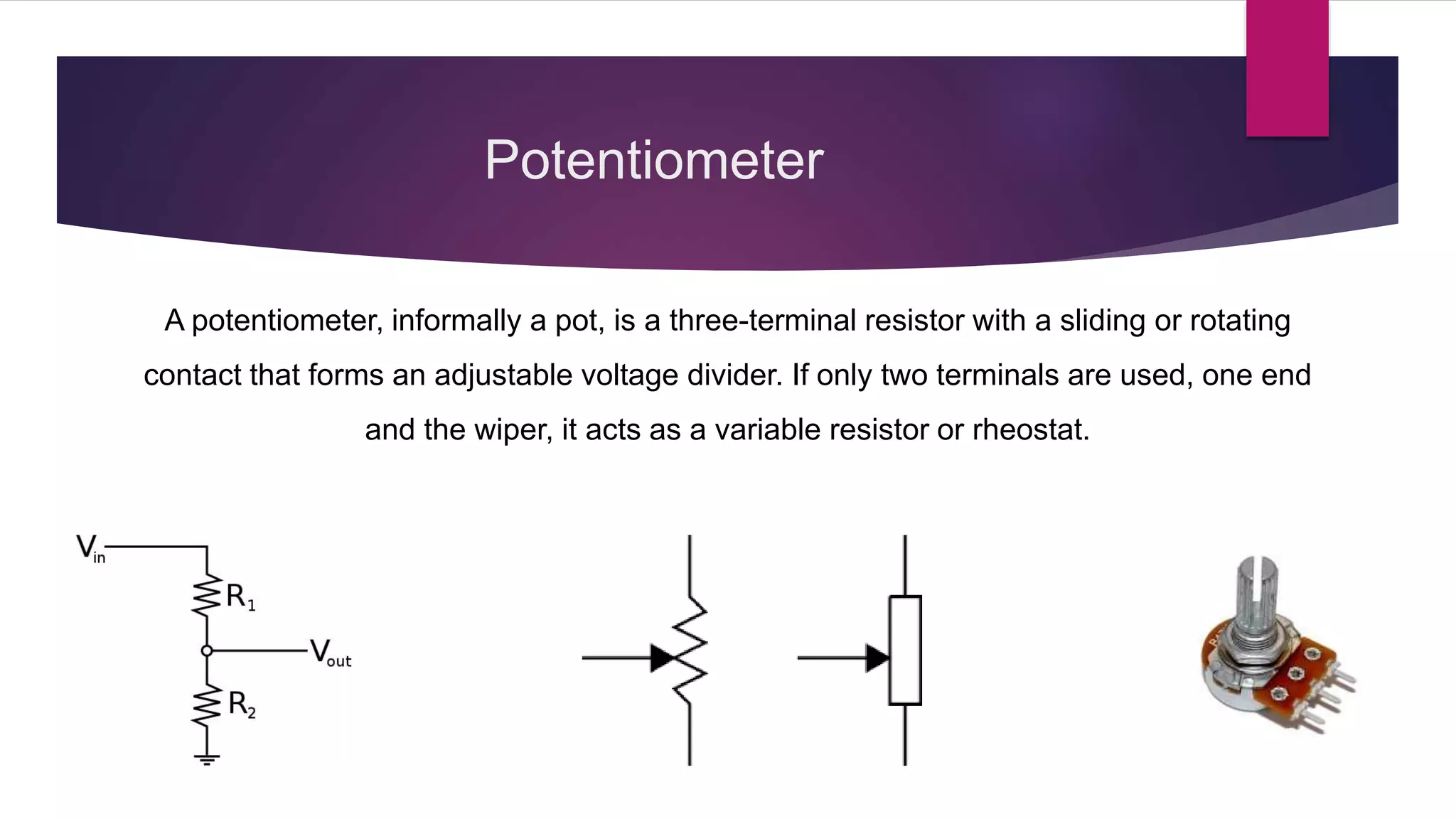
Descriptions of essential electronic components like LED, push button, potentiometer, and their uses.
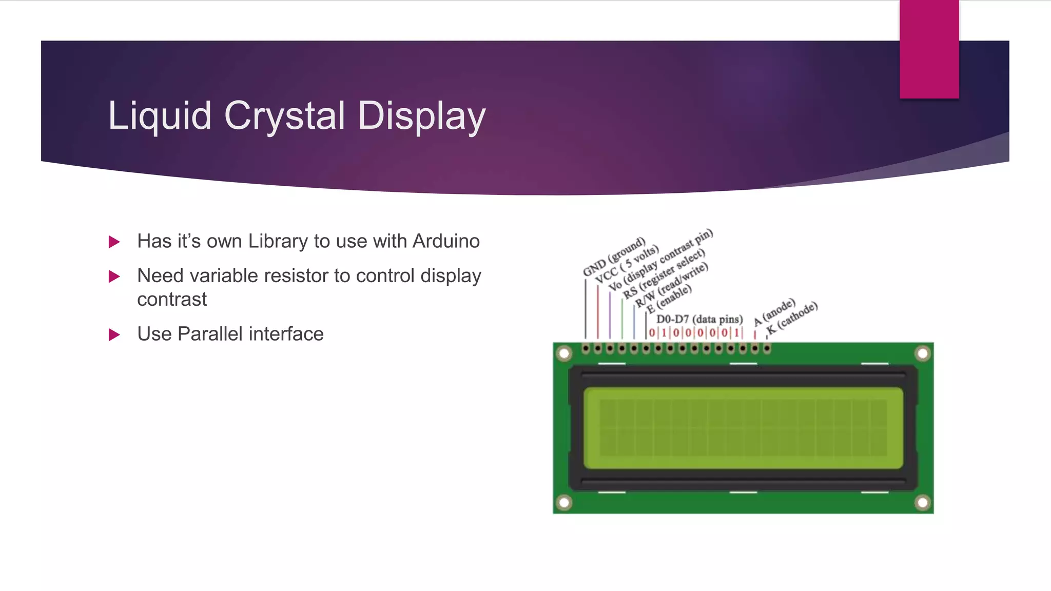
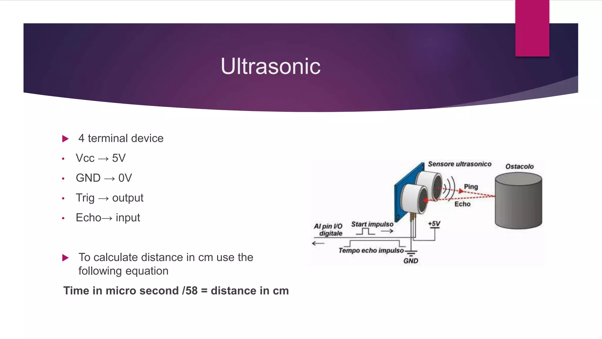
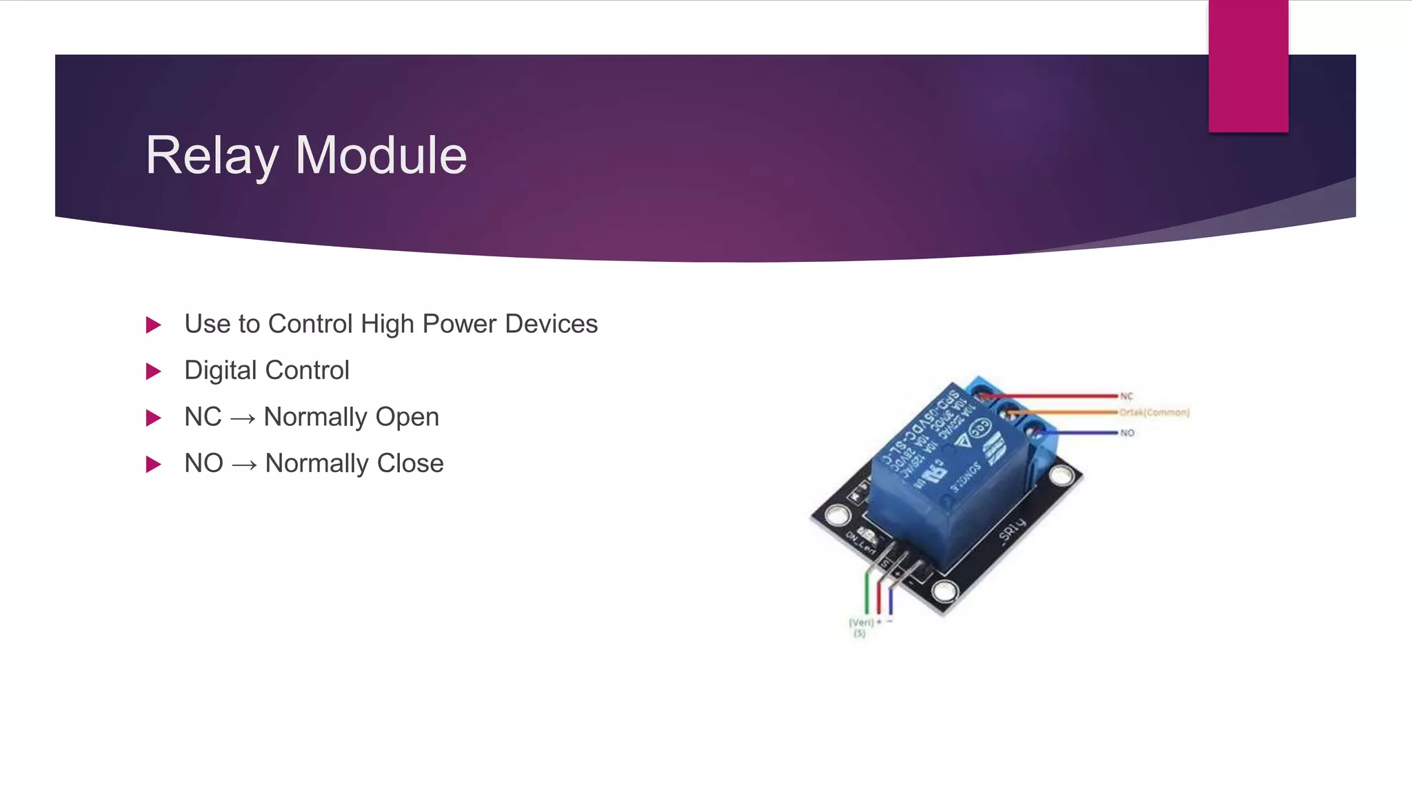
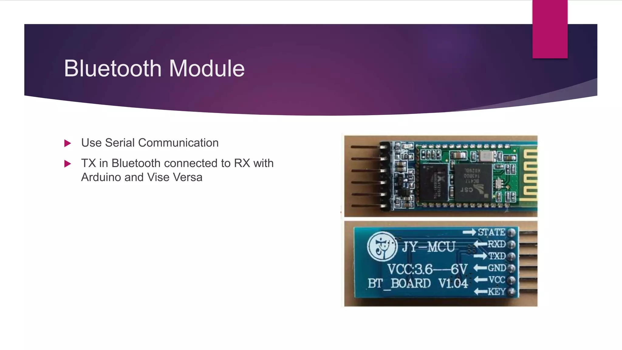
Detailed overview of important modules like LCD, ultrasonic sensor, Bluetooth module, etc.
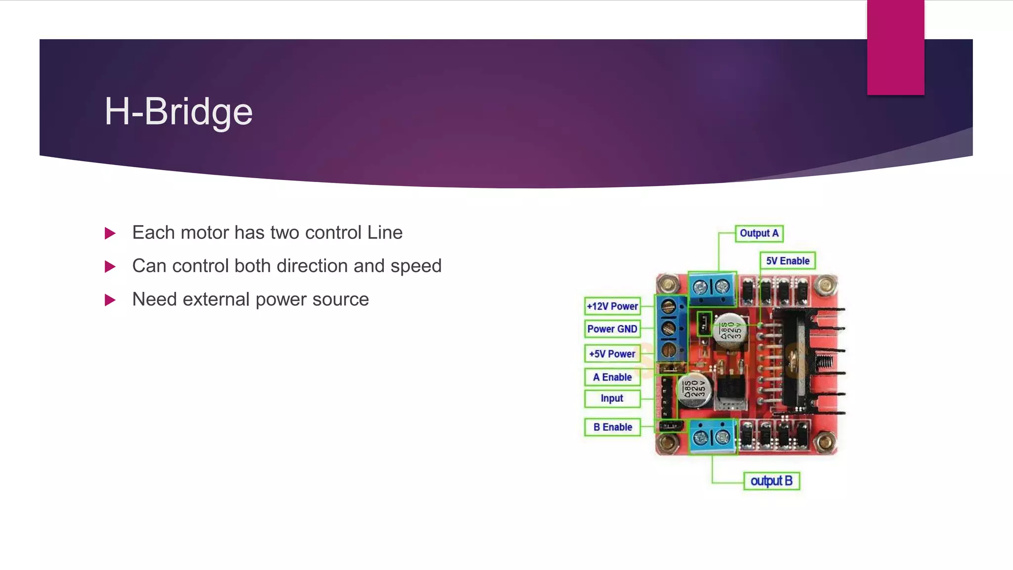
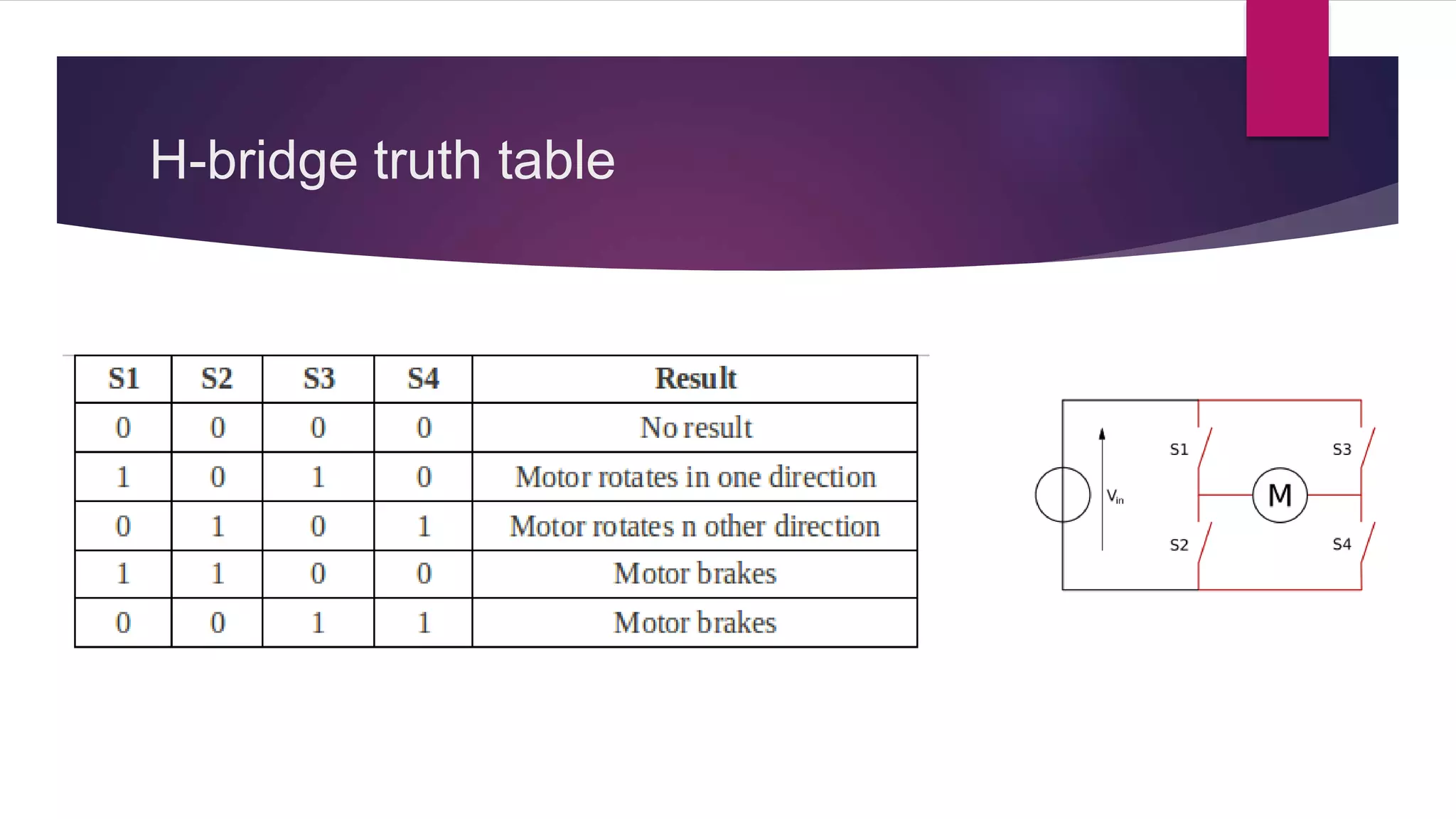
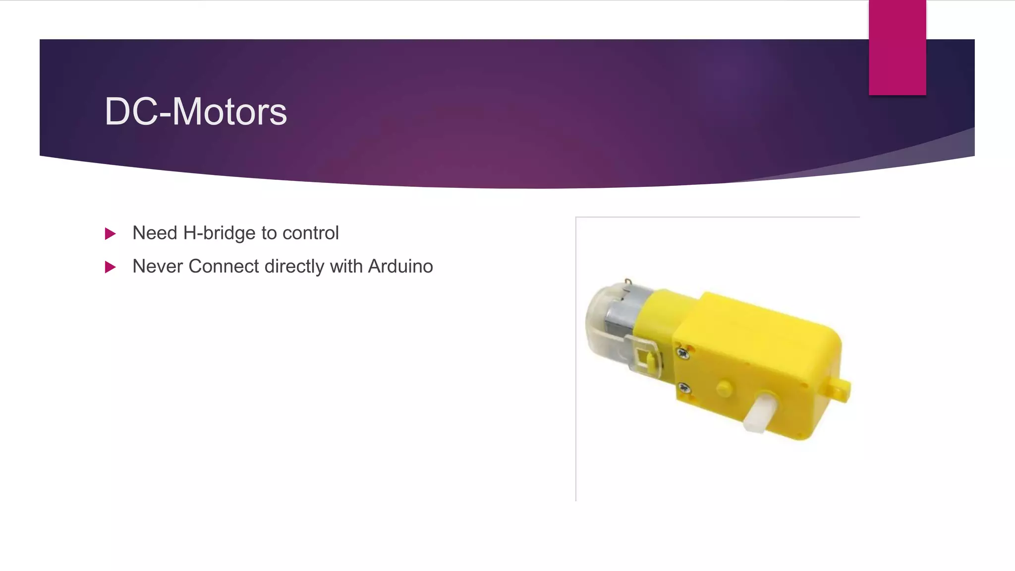
Concepts of motor control using H-bridge in Arduino, discussing various motor types.