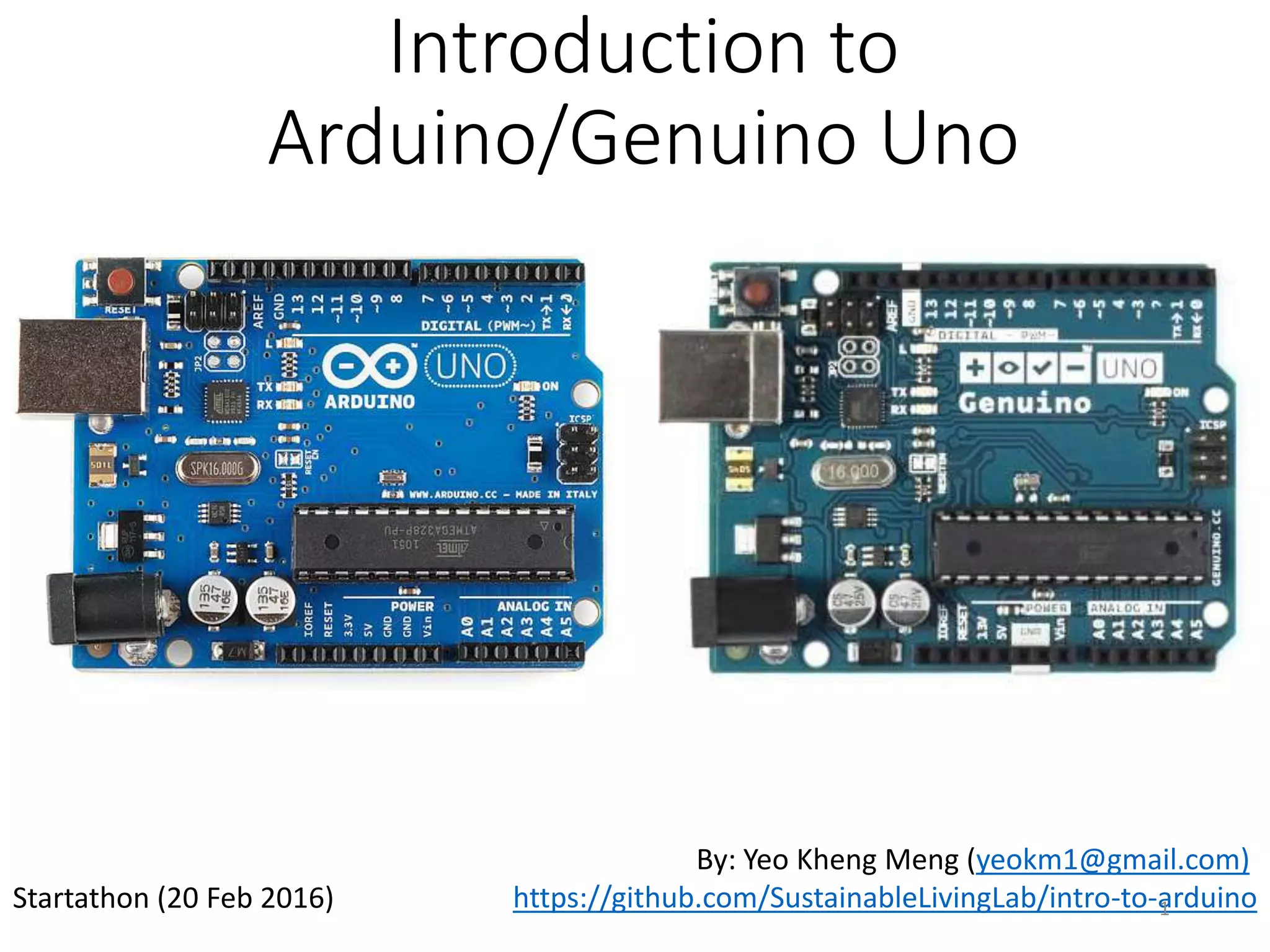
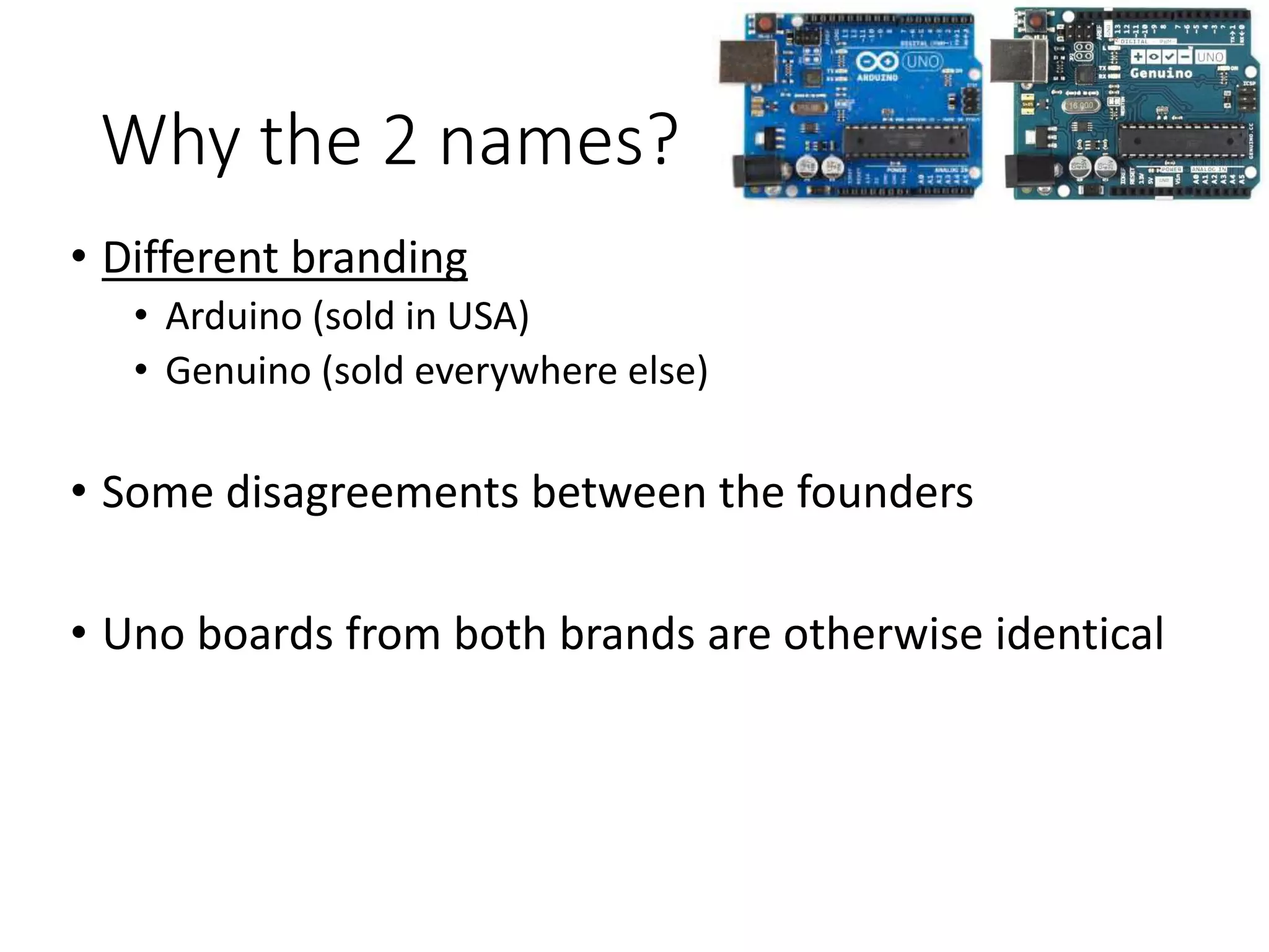
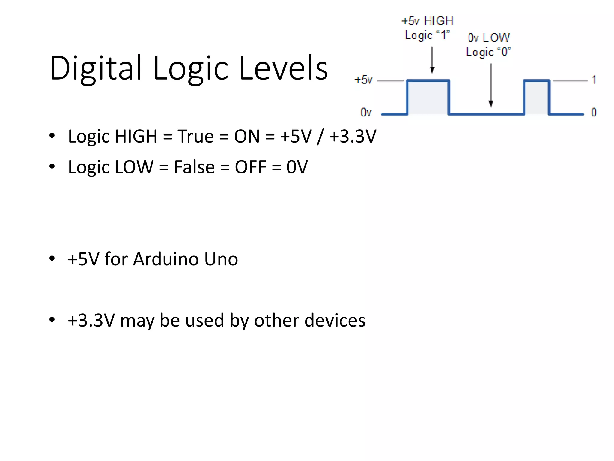
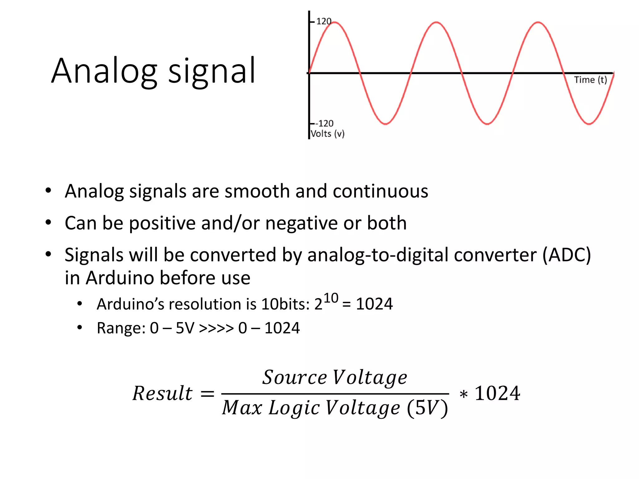
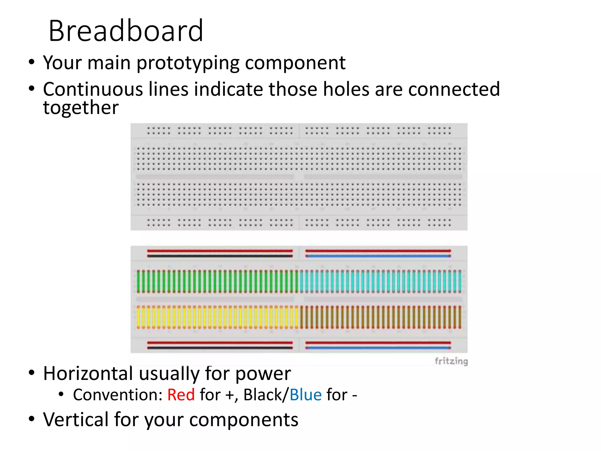
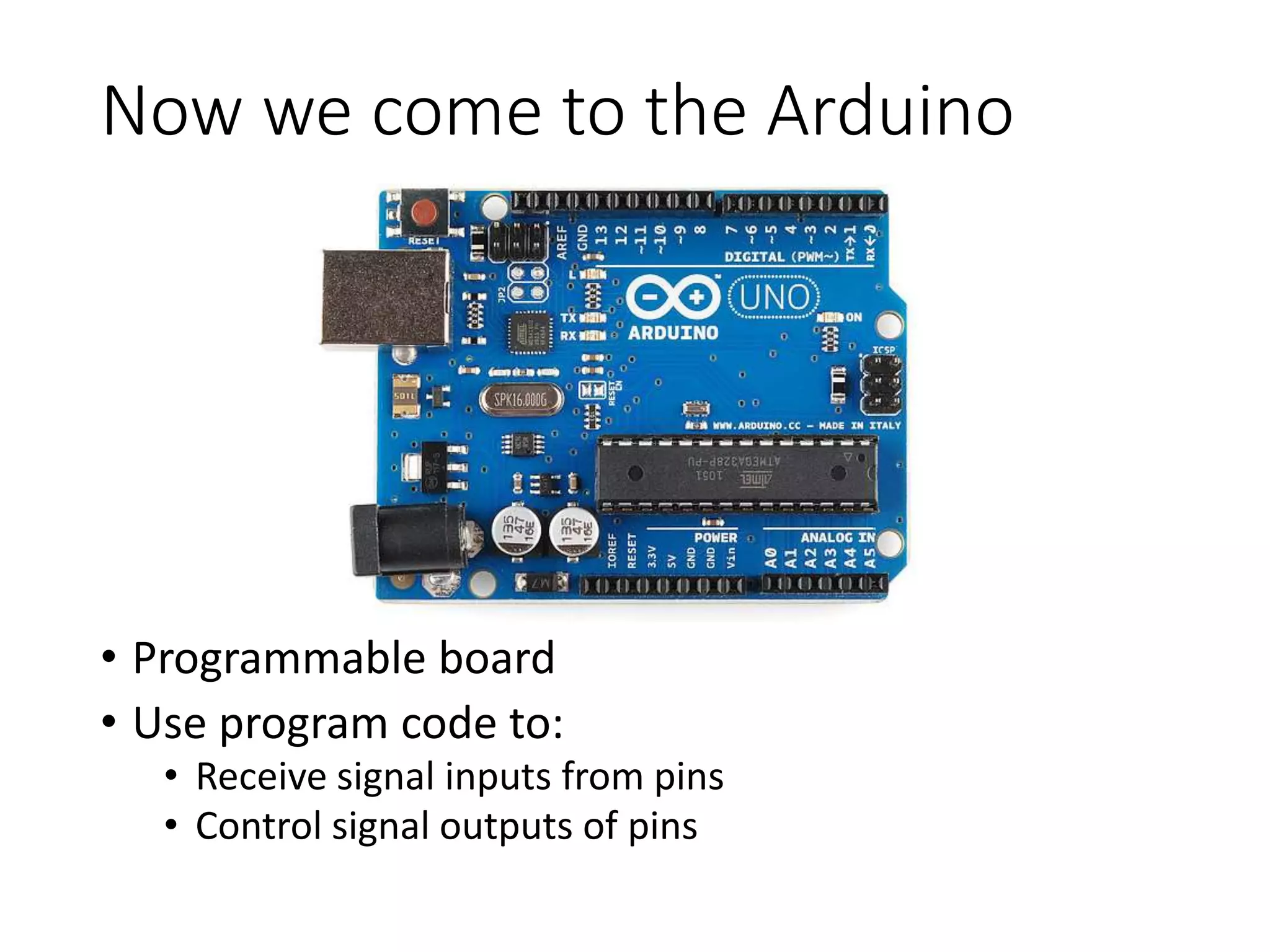
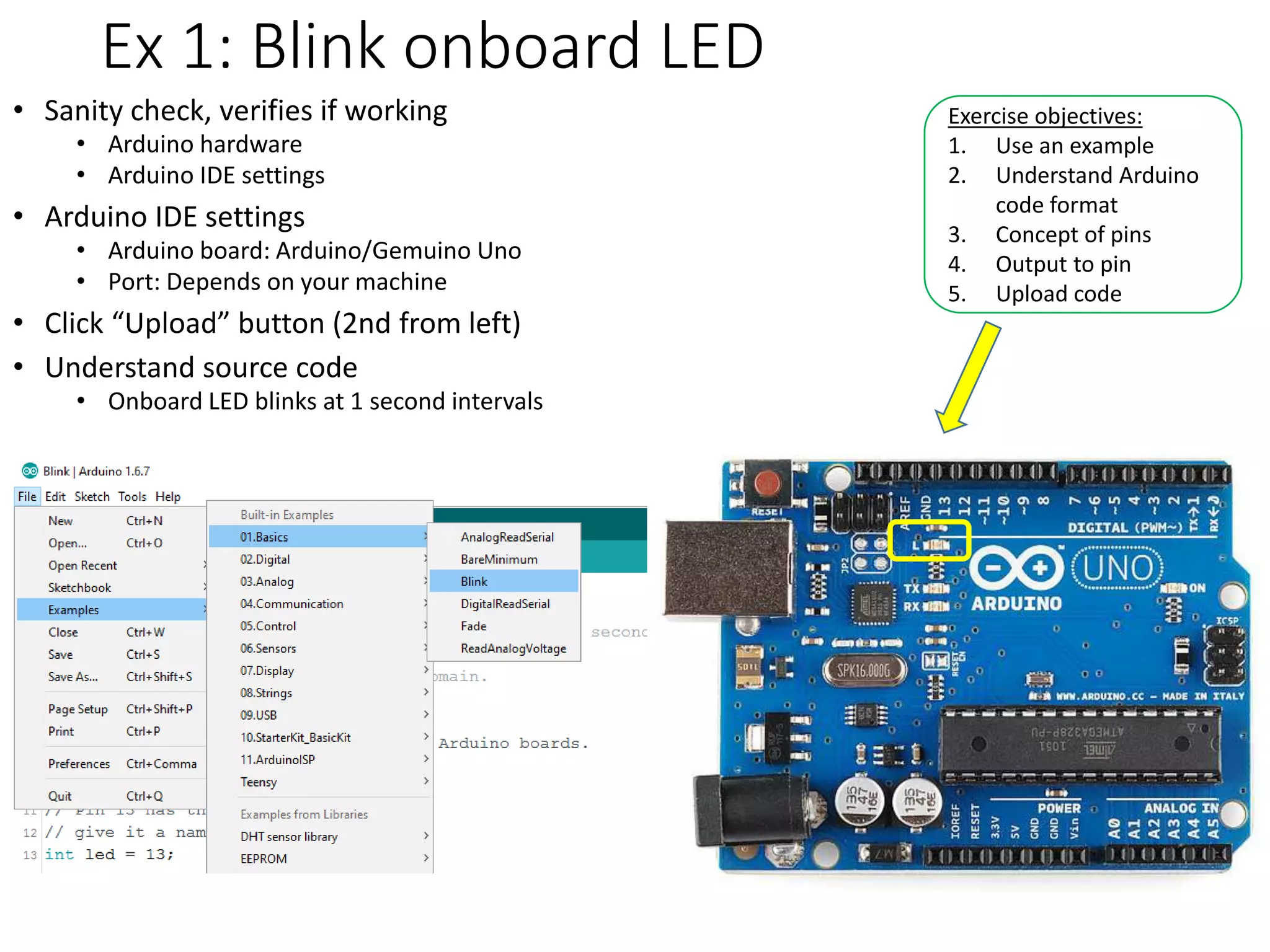
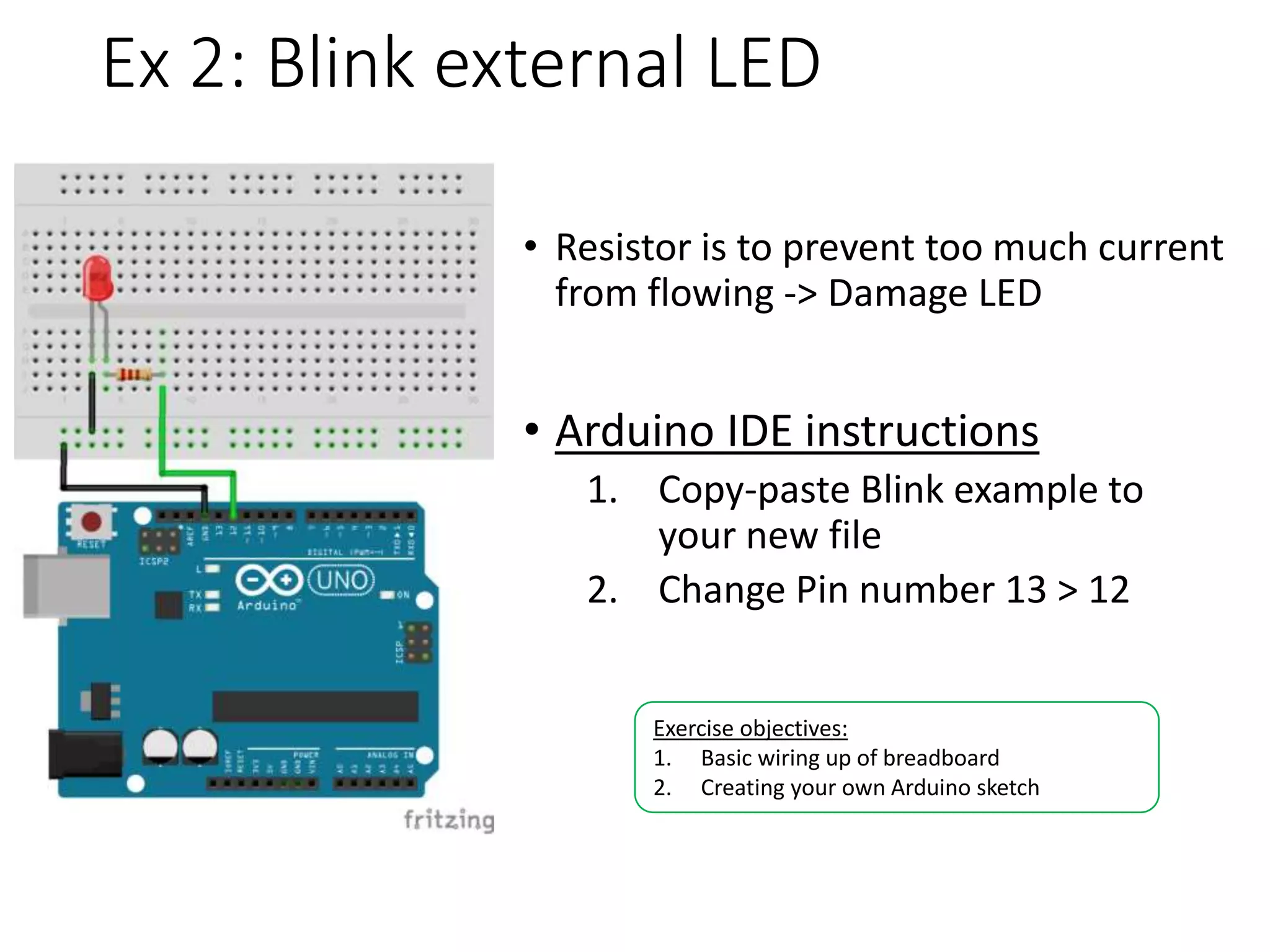
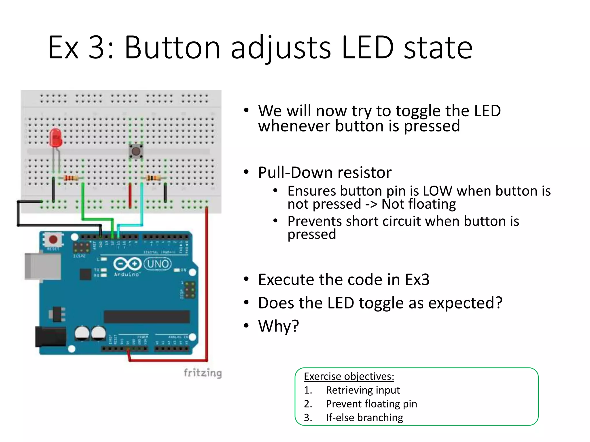
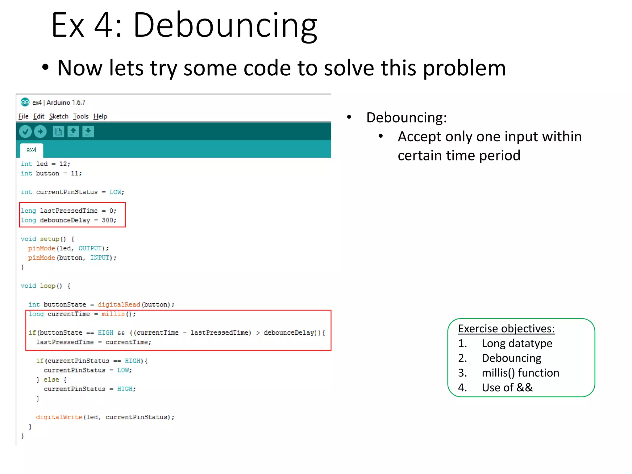
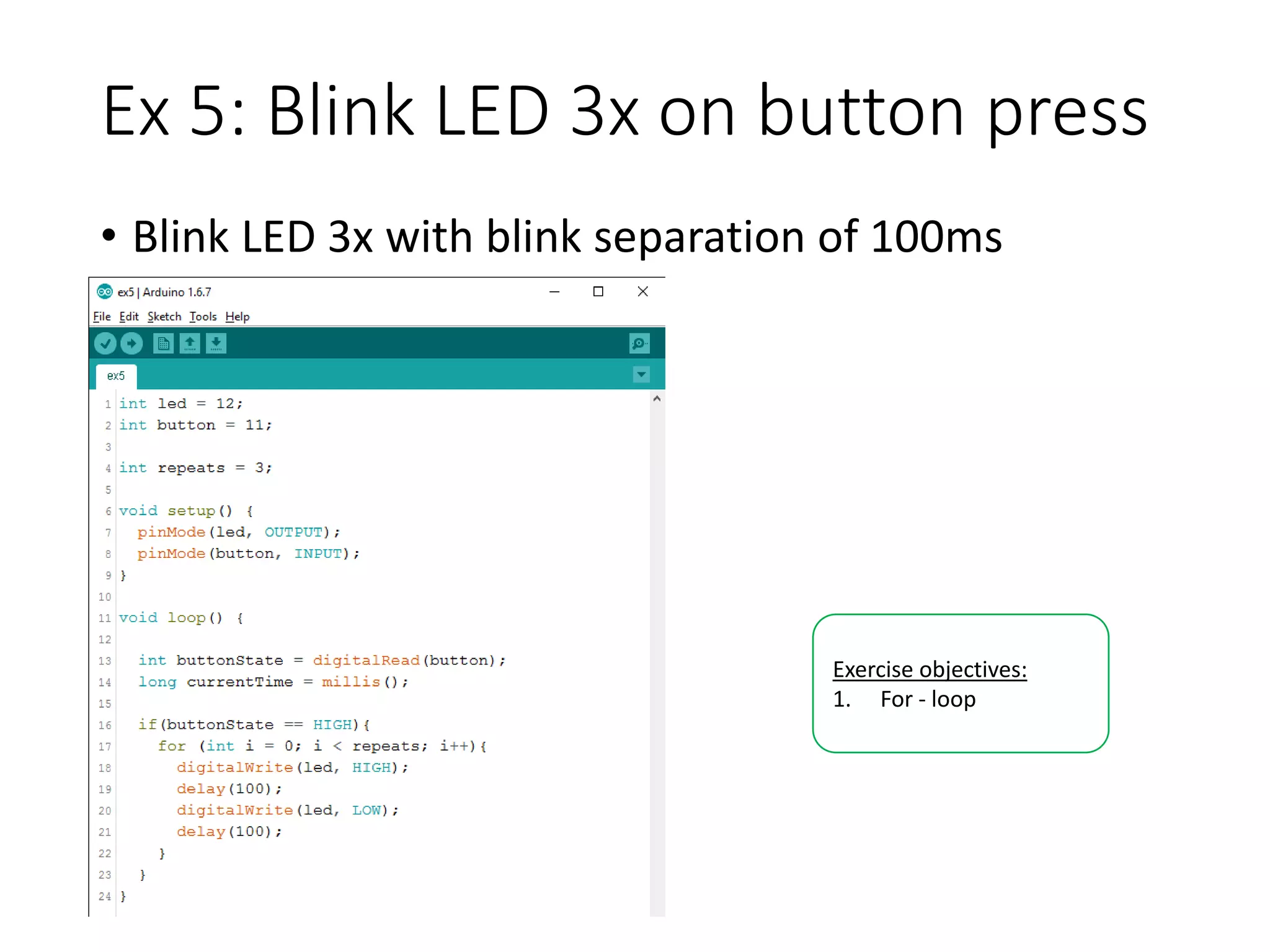
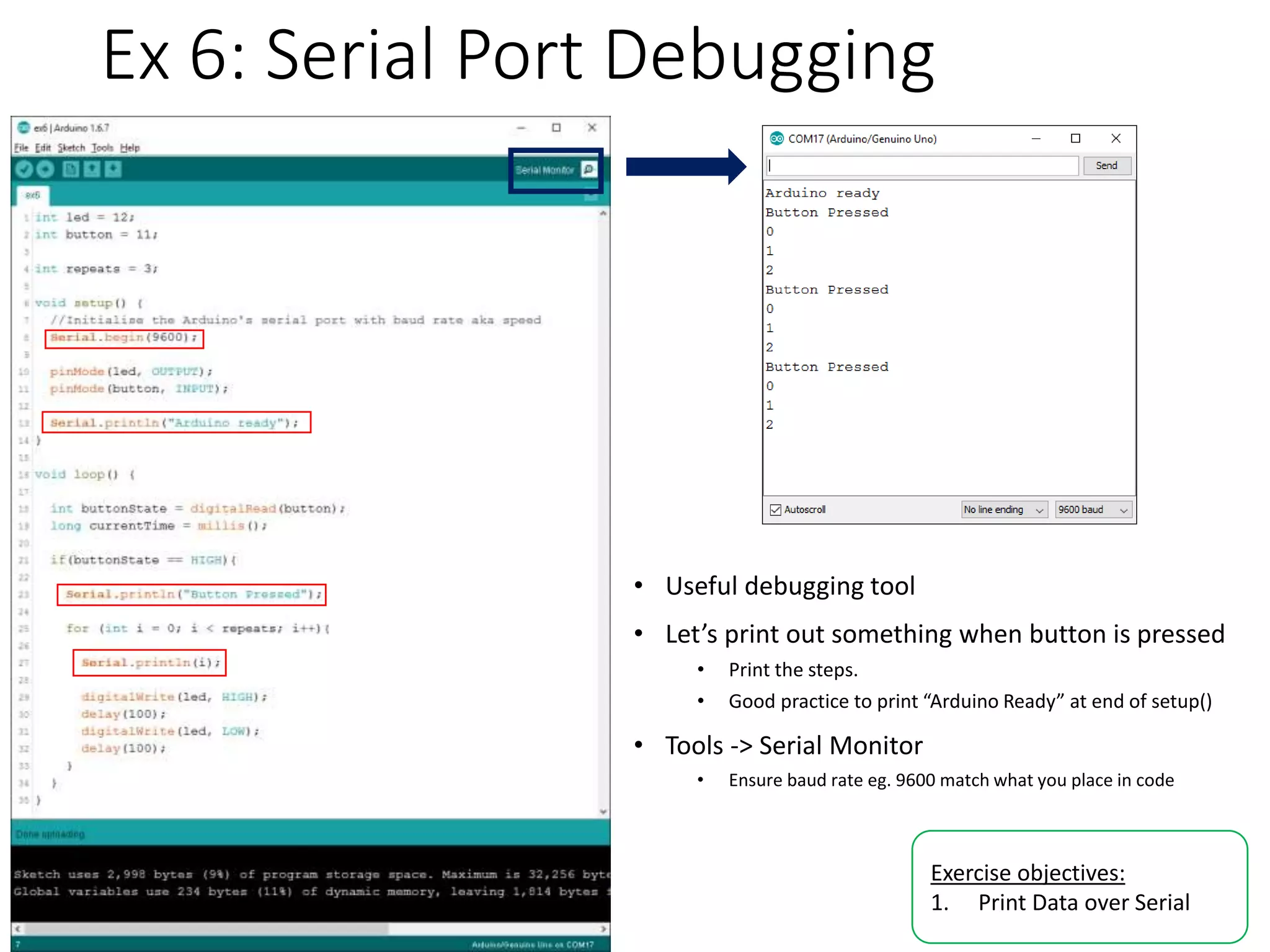
Introduction to Arduino/Genuino Uno By: Yeo Kheng Meng (yeokm1@gmail.com) https://github.com/SustainableLivingLab/intro-to-arduinoStartathon (20 Feb 2016) 1
Components/Software check • Laptop loaded with Arduino IDE • Whole Hackpack or at least • Arduino Uno • Breadboard • USB cable • LED • Button • 220 ohm resistor • 10k ohm resistor • At least a few jumper wires
Why the 2 names? • Different branding • Arduino (sold in USA) • Genuino (sold everywhere else) • Some disagreements between the founders • Uno boards from both brands are otherwise identical
First some electronic basics
Digital Logic Levels • Logic HIGH = True = ON = +5V / +3.3V • Logic LOW = False = OFF = 0V • +5V for Arduino Uno • +3.3V may be used by other devices
Analog signal • Analog signals are smooth and continuous • Can be positive and/or negative or both • Signals will be converted by analog-to-digital converter (ADC) in Arduino before use • Arduino’s resolution is 10bits: 210 = 1024 • Range: 0 – 5V >>>> 0 – 1024 𝑅𝑒𝑠𝑢𝑙𝑡 = 𝑆𝑜𝑢𝑟𝑐𝑒 𝑉𝑜𝑙𝑡𝑎𝑔𝑒 𝑀𝑎𝑥 𝐿𝑜𝑔𝑖𝑐 𝑉𝑜𝑙𝑡𝑎𝑔𝑒 (5𝑉) ∗ 1024
Breadboard • Your main prototyping component • Continuous lines indicate those holes are connected together • Horizontal usually for power • Convention: Red for +, Black/Blue for - • Vertical for your components
Now we come to the Arduino • Programmable board • Use program code to: • Receive signal inputs from pins • Control signal outputs of pins
Ex 1: Blink onboard LED • Sanity check, verifies if working • Arduino hardware • Arduino IDE settings • Arduino IDE settings • Arduino board: Arduino/Gemuino Uno • Port: Depends on your machine • Click “Upload” button (2nd from left) • Understand source code • Onboard LED blinks at 1 second intervals Exercise objectives: 1. Use an example 2. Understand Arduino code format 3. Concept of pins 4. Output to pin 5. Upload code
Create new Arduino file 1. Create folder on desktop 2. File -> New 3. Name program filename same as folder name • Example: myblinker.ino
Ex 2: Blink external LED • 220ohm resistor is to prevent too much current from flowing -> Damage LED • Arduino IDE instructions 1. Copy-paste Blink example to your new file 2. Change Pin number 13 > 12 Exercise objectives: 1. Basic wiring up of breadboard 2. Creating your own Arduino sketch
Ex 3: Button adjusts LED state • We will now try to toggle the LED whenever button is pressed • 10k ohm pull-down resistor • Ensures button pin is LOW when button is not pressed -> Not floating • Prevents short circuit when button is pressed • Execute the code in Ex3 • Does the LED toggle as expected? • Why? Exercise objectives: 1. Retrieving input 2. Prevent floating pin 3. If-else branching
Ex 4: Debouncing • Now lets try some code to solve this problem Exercise objectives: 1. Long datatype 2. Debouncing 3. millis() function 4. Use of && • Debouncing: • Accept only one input within certain time period
Ex 5: Blink LED 3x on button press • Blink LED 3x with blink separation of 100ms Exercise objectives: 1. For - loop
Ex 6: Serial Port Debugging • Useful debugging tool • Let’s print out something when button is pressed • Print the steps. • Good practice to print “Arduino Ready” at end of setup() • Tools -> Serial Monitor • Ensure baud rate eg. 9600 match what you place in code Exercise objectives: 1. Print Data over Serial

Introduction to Arduino

  • 1.
    Introduction to Arduino/Genuino Uno By:Yeo Kheng Meng (yeokm1@gmail.com) https://github.com/SustainableLivingLab/intro-to-arduinoStartathon (20 Feb 2016) 1
  • 2.
    Components/Software check • Laptoploaded with Arduino IDE • Whole Hackpack or at least • Arduino Uno • Breadboard • USB cable • LED • Button • 220 ohm resistor • 10k ohm resistor • At least a few jumper wires
  • 3.
    Why the 2names? • Different branding • Arduino (sold in USA) • Genuino (sold everywhere else) • Some disagreements between the founders • Uno boards from both brands are otherwise identical
  • 4.
  • 5.
    Digital Logic Levels •Logic HIGH = True = ON = +5V / +3.3V • Logic LOW = False = OFF = 0V • +5V for Arduino Uno • +3.3V may be used by other devices
  • 6.
    Analog signal • Analogsignals are smooth and continuous • Can be positive and/or negative or both • Signals will be converted by analog-to-digital converter (ADC) in Arduino before use • Arduino’s resolution is 10bits: 210 = 1024 • Range: 0 – 5V >>>> 0 – 1024 𝑅𝑒𝑠𝑢𝑙𝑡 = 𝑆𝑜𝑢𝑟𝑐𝑒 𝑉𝑜𝑙𝑡𝑎𝑔𝑒 𝑀𝑎𝑥 𝐿𝑜𝑔𝑖𝑐 𝑉𝑜𝑙𝑡𝑎𝑔𝑒 (5𝑉) ∗ 1024
  • 7.
    Breadboard • Your mainprototyping component • Continuous lines indicate those holes are connected together • Horizontal usually for power • Convention: Red for +, Black/Blue for - • Vertical for your components
  • 8.
    Now we cometo the Arduino • Programmable board • Use program code to: • Receive signal inputs from pins • Control signal outputs of pins
  • 9.
    Ex 1: Blinkonboard LED • Sanity check, verifies if working • Arduino hardware • Arduino IDE settings • Arduino IDE settings • Arduino board: Arduino/Gemuino Uno • Port: Depends on your machine • Click “Upload” button (2nd from left) • Understand source code • Onboard LED blinks at 1 second intervals Exercise objectives: 1. Use an example 2. Understand Arduino code format 3. Concept of pins 4. Output to pin 5. Upload code
  • 10.
    Create new Arduinofile 1. Create folder on desktop 2. File -> New 3. Name program filename same as folder name • Example: myblinker.ino
  • 11.
    Ex 2: Blinkexternal LED • 220ohm resistor is to prevent too much current from flowing -> Damage LED • Arduino IDE instructions 1. Copy-paste Blink example to your new file 2. Change Pin number 13 > 12 Exercise objectives: 1. Basic wiring up of breadboard 2. Creating your own Arduino sketch
  • 12.
    Ex 3: Buttonadjusts LED state • We will now try to toggle the LED whenever button is pressed • 10k ohm pull-down resistor • Ensures button pin is LOW when button is not pressed -> Not floating • Prevents short circuit when button is pressed • Execute the code in Ex3 • Does the LED toggle as expected? • Why? Exercise objectives: 1. Retrieving input 2. Prevent floating pin 3. If-else branching
  • 13.
    Ex 4: Debouncing •Now lets try some code to solve this problem Exercise objectives: 1. Long datatype 2. Debouncing 3. millis() function 4. Use of && • Debouncing: • Accept only one input within certain time period
  • 14.
    Ex 5: BlinkLED 3x on button press • Blink LED 3x with blink separation of 100ms Exercise objectives: 1. For - loop
  • 15.
    Ex 6: SerialPort Debugging • Useful debugging tool • Let’s print out something when button is pressed • Print the steps. • Good practice to print “Arduino Ready” at end of setup() • Tools -> Serial Monitor • Ensure baud rate eg. 9600 match what you place in code Exercise objectives: 1. Print Data over Serial