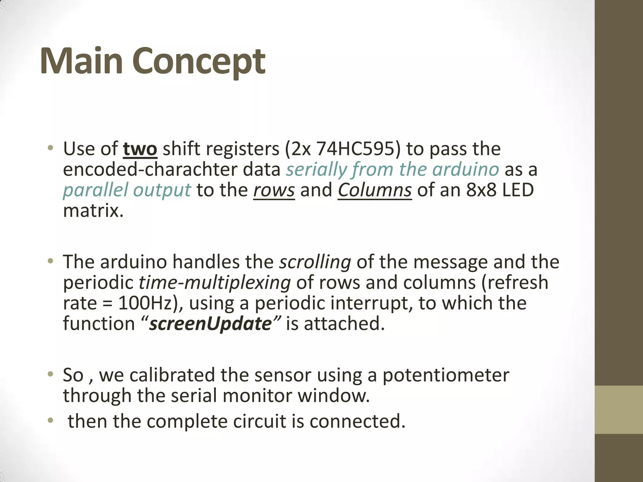
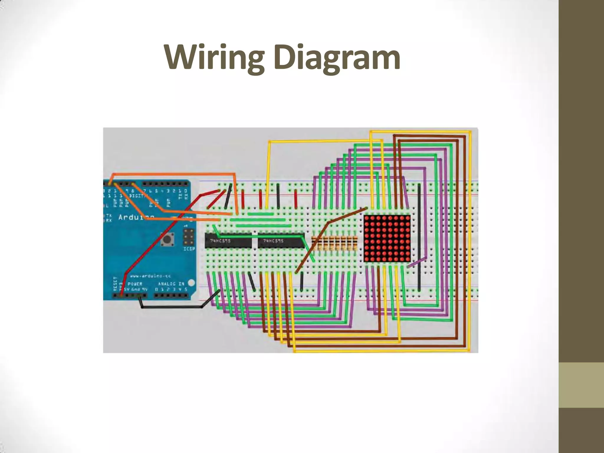
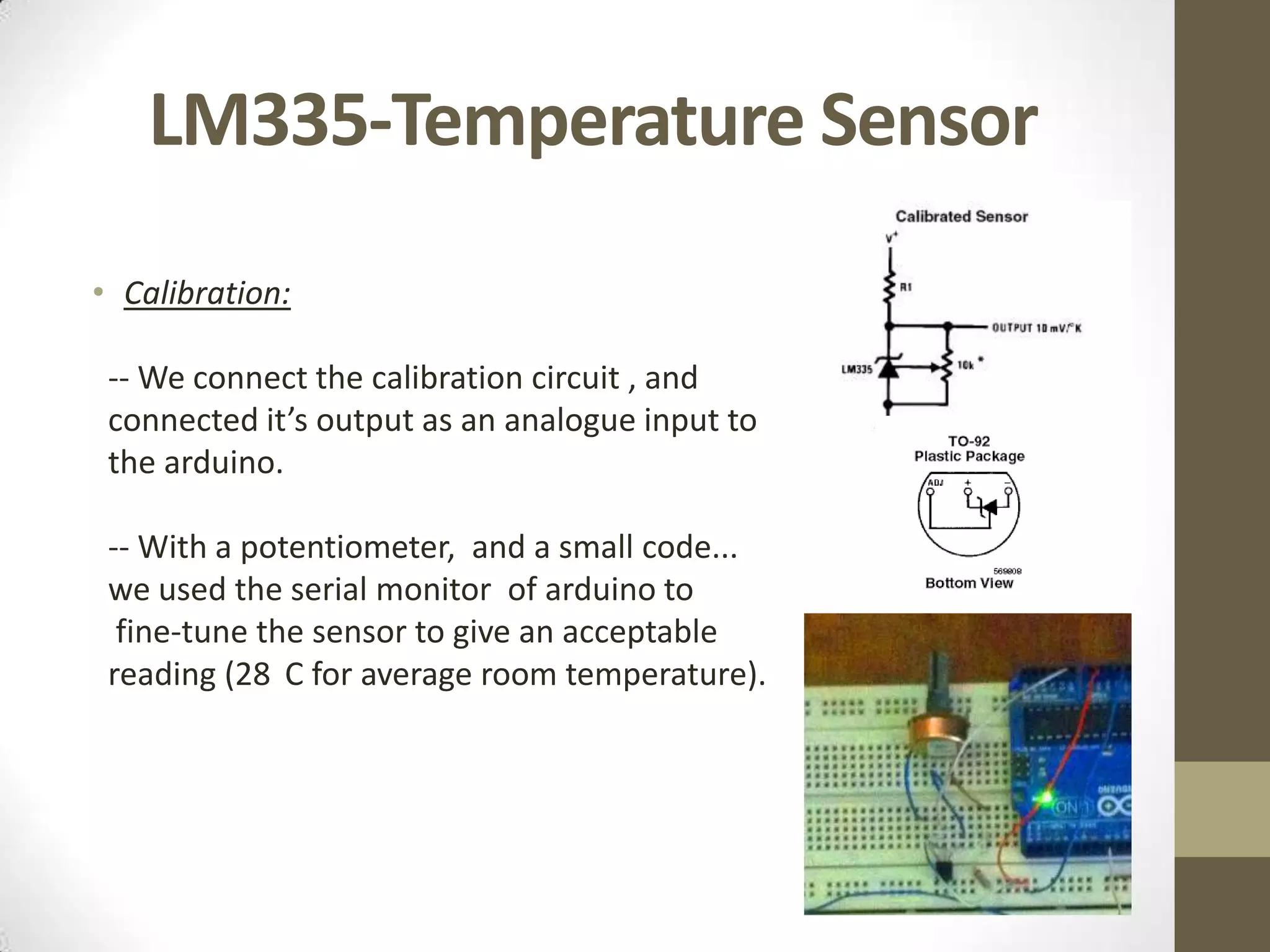
Arduino Final Project By: Mhmoud Salama. Hussam Hamdy.
Main Project • To make a temperature sensor that outputs the reading as a scrolling message on a LED matrix. • We used a LED matrix which is a common anode 8x8 display. • Wired on breadboards.
Main Concept • Use of two shift registers (2x 74HC595) to pass the encoded-charachter data serially from the arduino as a parallel output to the rows and Columns of an 8x8 LED matrix. • The arduino handles the scrolling of the message and the periodic time-multiplexing of rows and columns (refresh rate = 100Hz), using a periodic interrupt, to which the function “screenUpdate” is attached. • So , we calibrated the sensor using a potentiometer through the serial monitor window. • then the complete circuit is connected.
Wiring Diagram
74HC595-Shift Registers -- An 8-bit shift register with Serial to parallel capability. -- We use two of them, Each one controlling eight rows/columns.
LM335-Temperature Sensor • Calibration: -- We connect the calibration circuit , and connected it’s output as an analogue input to the arduino. -- With a potentiometer, and a small code... we used the serial monitor of arduino to fine-tune the sensor to give an acceptable reading (28 C for average room temperature).
CODE • #include <TimerOne.h> • #include <charEncodings.h> // Each charachter and it’s (8x8 LED matrix)-mapped code. • // BASIC PIN CONFIGURATION • // AND DECLARATIONS • //Pin connected to Pin 12 of 74HC595 (Latch) • int latchPin = 8; • //Pin connected to Pin 11 of 74HC595 (Clock) • int clockPin = 12; • //Pin connected to Pin 14 of 74HC595 (Data) • int dataPin = 11; • // pin for the potentiometer to control the scrolling speed • int potPin = 5; • // pin for reading the temperature • int tempPin = 4; • // this is the gobal array that represents what the matrix • // is currently displaying • uint8_t led[8];
CODE • void setup() • { //set pins to output • pinMode(latchPin, OUTPUT); • pinMode(clockPin, OUTPUT); • pinMode(dataPin, OUTPUT); • pinMode(potPin, INPUT); • pinMode(tempPin, INPUT); • analogReference(INTERNAL); • // attach the screenUpdate function to the interrupt timer • // Period=10,000micro-second /refresh rate =100Hz • Timer1.initialize(10000); • Timer1.attachInterrupt(screenUpdate); • }
CODE • //Continuous LOOP • void loop() • { • long counter1 = 0; • long counter2 = 0; • char reading[10]; • char buffer[18]; • if (counter1++ >=100000) { • counter2++; • } • if (counter2 >= 10000) { • counter1 = 0; • counter2 = 0; • } getTemp(reading); displayScrolledText(reading); }
The (displayScrolledText ) Function • void displayScrolledText(char* textToDisplay) • { • int textLen = strlen(textToDisplay); • char charLeft, charRight; • // scan through entire string one column at a time and call • // function to display 8 columns to the right • for (int col = 1; col <= textLen*8; col++) • { • • // if (col-1) is exact multiple of 8 then only one character • // involved, so just display that one • if ((col-1) % 8 == 0 ) • { • char charToDisplay = textToDisplay[(col-1)/8]; • • for (int j=0; j<8; j++) • { • led[j] = charBitmaps[charToDisplay][j]; • } • } • else • { • int charLeftIndex = (col-1)/8; • int charRightIndex = (col-1)/8+1; • charLeft = textToDisplay[charLeftIndex];
• // check we are not off the end of the string • if (charRightIndex <= textLen) • { • charRight = textToDisplay[charRightIndex]; • } • else • { • charRight = ' '; • } • setMatrixFromPosition(charLeft, charRight, (col-1) % 8); • } • int delayTime = analogRead(potPin); • delay (delayTime); • } •}
• void shiftIt(byte dataOut) { • // Shift out 8 bits LSB first, • // on rising edge of clock • boolean pinState; • //clear shift register read for sending data • digitalWrite(dataPin, LOW); • // for each bit in dataOut send out a bit • for (int i=0; i<=7; i++) { • //set clockPin to LOW prior to sending bit • digitalWrite(clockPin, LOW); • // if the value of DataOut and (logical AND) a bitmask • // are true, set pinState to 1 (HIGH) • if ( dataOut & (1<<i) ) { • pinState = HIGH; • } • else { • pinState = LOW; • } • //sets dataPin to HIGH or LOW depending on pinState • digitalWrite(dataPin, pinState); • //send bit out on rising edge of clock • digitalWrite(clockPin, HIGH); • digitalWrite(dataPin, LOW); • }
• //stop shifting • digitalWrite(clockPin, LOW); • } • boolean isKeyboardInput() { • // returns true is there is any characters in the keyboard buffer • return (Serial.available() > 0); • } • } • // terminate the string • readString[index] = '0'; • }
• void setMatrixFromPosition(char charLeft, char charRight, int col) { • // take col left most columns from left character and bitwise OR with 8-col from • // the right character • for (int j=0; j<8; j++) { • led[j] = charBitmaps[charLeft][j] << col | charBitmaps[charRight][j] >> 8-col; • } • } • void screenUpdate() { • uint8_t col = B00000001; • for (byte k = 0; k < 8; k++) { • digitalWrite(latchPin, LOW); // Open up the latch ready to receive data • shiftIt(~led[7-k]); • shiftIt(col); • digitalWrite(latchPin, HIGH); // Close the latch, sending the registers data to the matrix • col = col << 1; • } • digitalWrite(latchPin, LOW); • shiftIt(~0 ); • shiftIt(255); • digitalWrite(latchPin, HIGH); • }
• void getTemp(char* reading) { • int span = 20; • int aRead = 0; • long temp; • char tmpStr[10]; • // average out several readings • for (int i = 0; i < span; i++) { • aRead = aRead+analogRead(tempPin); • } • aRead = aRead / span; • temp = ((100*1.1*aRead)/1024)*10; • reading[0] = '0'; • itoa(temp/10, tmpStr, 10); • strcat(reading,tmpStr); • strcat(reading, "."); • itoa(temp % 10, tmpStr, 10); • strcat(reading, tmpStr); • strcat(reading, "C"); • }

Temperature sensor with a led matrix display (arduino controlled)

  • 1.
    Arduino Final Project By:Mhmoud Salama. Hussam Hamdy.
  • 2.
    Main Project • Tomake a temperature sensor that outputs the reading as a scrolling message on a LED matrix. • We used a LED matrix which is a common anode 8x8 display. • Wired on breadboards.
  • 3.
    Main Concept • Useof two shift registers (2x 74HC595) to pass the encoded-charachter data serially from the arduino as a parallel output to the rows and Columns of an 8x8 LED matrix. • The arduino handles the scrolling of the message and the periodic time-multiplexing of rows and columns (refresh rate = 100Hz), using a periodic interrupt, to which the function “screenUpdate” is attached. • So , we calibrated the sensor using a potentiometer through the serial monitor window. • then the complete circuit is connected.
  • 4.
  • 5.
    74HC595-Shift Registers -- An8-bit shift register with Serial to parallel capability. -- We use two of them, Each one controlling eight rows/columns.
  • 6.
    LM335-Temperature Sensor • Calibration: -- We connect the calibration circuit , and connected it’s output as an analogue input to the arduino. -- With a potentiometer, and a small code... we used the serial monitor of arduino to fine-tune the sensor to give an acceptable reading (28 C for average room temperature).
  • 7.
    CODE • #include <TimerOne.h> • #include <charEncodings.h> // Each charachter and it’s (8x8 LED matrix)-mapped code. • // BASIC PIN CONFIGURATION • // AND DECLARATIONS • //Pin connected to Pin 12 of 74HC595 (Latch) • int latchPin = 8; • //Pin connected to Pin 11 of 74HC595 (Clock) • int clockPin = 12; • //Pin connected to Pin 14 of 74HC595 (Data) • int dataPin = 11; • // pin for the potentiometer to control the scrolling speed • int potPin = 5; • // pin for reading the temperature • int tempPin = 4; • // this is the gobal array that represents what the matrix • // is currently displaying • uint8_t led[8];
  • 8.
    CODE • void setup() •{ //set pins to output • pinMode(latchPin, OUTPUT); • pinMode(clockPin, OUTPUT); • pinMode(dataPin, OUTPUT); • pinMode(potPin, INPUT); • pinMode(tempPin, INPUT); • analogReference(INTERNAL); • // attach the screenUpdate function to the interrupt timer • // Period=10,000micro-second /refresh rate =100Hz • Timer1.initialize(10000); • Timer1.attachInterrupt(screenUpdate); • }
  • 9.
    CODE • //Continuous LOOP •void loop() • { • long counter1 = 0; • long counter2 = 0; • char reading[10]; • char buffer[18]; • if (counter1++ >=100000) { • counter2++; • } • if (counter2 >= 10000) { • counter1 = 0; • counter2 = 0; • } getTemp(reading); displayScrolledText(reading); }
  • 10.
    The (displayScrolledText )Function • void displayScrolledText(char* textToDisplay) • { • int textLen = strlen(textToDisplay); • char charLeft, charRight; • // scan through entire string one column at a time and call • // function to display 8 columns to the right • for (int col = 1; col <= textLen*8; col++) • { • • // if (col-1) is exact multiple of 8 then only one character • // involved, so just display that one • if ((col-1) % 8 == 0 ) • { • char charToDisplay = textToDisplay[(col-1)/8]; • • for (int j=0; j<8; j++) • { • led[j] = charBitmaps[charToDisplay][j]; • } • } • else • { • int charLeftIndex = (col-1)/8; • int charRightIndex = (col-1)/8+1; • charLeft = textToDisplay[charLeftIndex];
  • 11.
    • // checkwe are not off the end of the string • if (charRightIndex <= textLen) • { • charRight = textToDisplay[charRightIndex]; • } • else • { • charRight = ' '; • } • setMatrixFromPosition(charLeft, charRight, (col-1) % 8); • } • int delayTime = analogRead(potPin); • delay (delayTime); • } •}
  • 12.
    void shiftIt(byte dataOut) { • // Shift out 8 bits LSB first, • // on rising edge of clock • boolean pinState; • //clear shift register read for sending data • digitalWrite(dataPin, LOW); • // for each bit in dataOut send out a bit • for (int i=0; i<=7; i++) { • //set clockPin to LOW prior to sending bit • digitalWrite(clockPin, LOW); • // if the value of DataOut and (logical AND) a bitmask • // are true, set pinState to 1 (HIGH) • if ( dataOut & (1<<i) ) { • pinState = HIGH; • } • else { • pinState = LOW; • } • //sets dataPin to HIGH or LOW depending on pinState • digitalWrite(dataPin, pinState); • //send bit out on rising edge of clock • digitalWrite(clockPin, HIGH); • digitalWrite(dataPin, LOW); • }
  • 13.
    • //stop shifting •digitalWrite(clockPin, LOW); • } • boolean isKeyboardInput() { • // returns true is there is any characters in the keyboard buffer • return (Serial.available() > 0); • } • } • // terminate the string • readString[index] = '0'; • }
  • 14.
    void setMatrixFromPosition(char charLeft, char charRight, int col) { • // take col left most columns from left character and bitwise OR with 8-col from • // the right character • for (int j=0; j<8; j++) { • led[j] = charBitmaps[charLeft][j] << col | charBitmaps[charRight][j] >> 8-col; • } • } • void screenUpdate() { • uint8_t col = B00000001; • for (byte k = 0; k < 8; k++) { • digitalWrite(latchPin, LOW); // Open up the latch ready to receive data • shiftIt(~led[7-k]); • shiftIt(col); • digitalWrite(latchPin, HIGH); // Close the latch, sending the registers data to the matrix • col = col << 1; • } • digitalWrite(latchPin, LOW); • shiftIt(~0 ); • shiftIt(255); • digitalWrite(latchPin, HIGH); • }
  • 15.
    void getTemp(char* reading) { • int span = 20; • int aRead = 0; • long temp; • char tmpStr[10]; • // average out several readings • for (int i = 0; i < span; i++) { • aRead = aRead+analogRead(tempPin); • } • aRead = aRead / span; • temp = ((100*1.1*aRead)/1024)*10; • reading[0] = '0'; • itoa(temp/10, tmpStr, 10); • strcat(reading,tmpStr); • strcat(reading, "."); • itoa(temp % 10, tmpStr, 10); • strcat(reading, tmpStr); • strcat(reading, "C"); • }