Download as PDF, PPTX
![Principle Sensors READ Your Sketch [C] inputs UPLOAD ARDUINO ATmega328 COMMUNICATE outputs Actuators WRITE](https://image.slidesharecdn.com/programmingarduinomakeymakey-120904143555-phpapp02/75/Programming-arduino-makeymakey-3-2048.jpg)


![Principle for game interface Sensors READ Your Sketch [C] inputs UPLOAD ARDUINO ATmega328 COMMUNICATE outputs Actuators WRITE](https://image.slidesharecdn.com/programmingarduinomakeymakey-120904143555-phpapp02/75/Programming-arduino-makeymakey-36-2048.jpg)
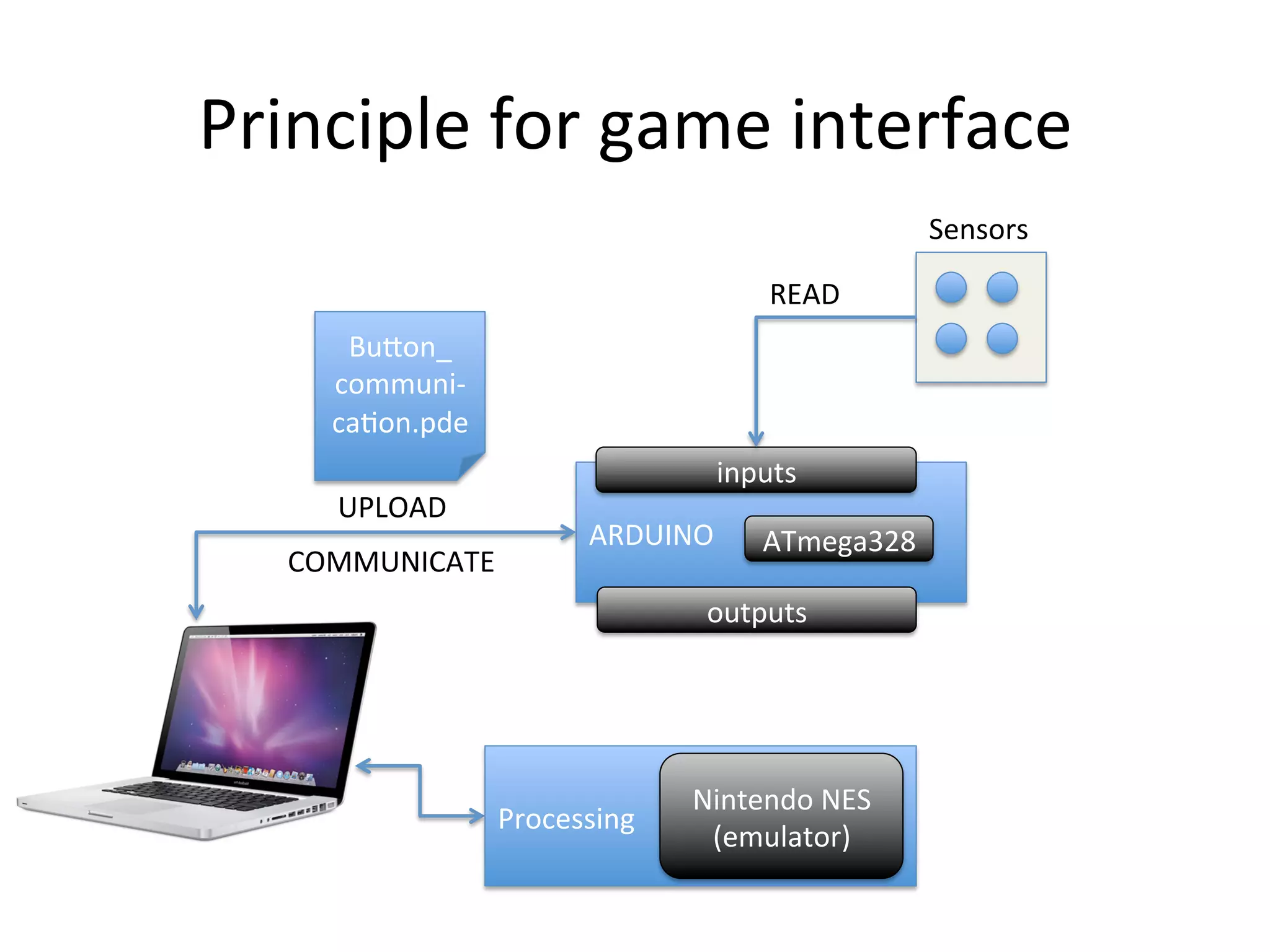

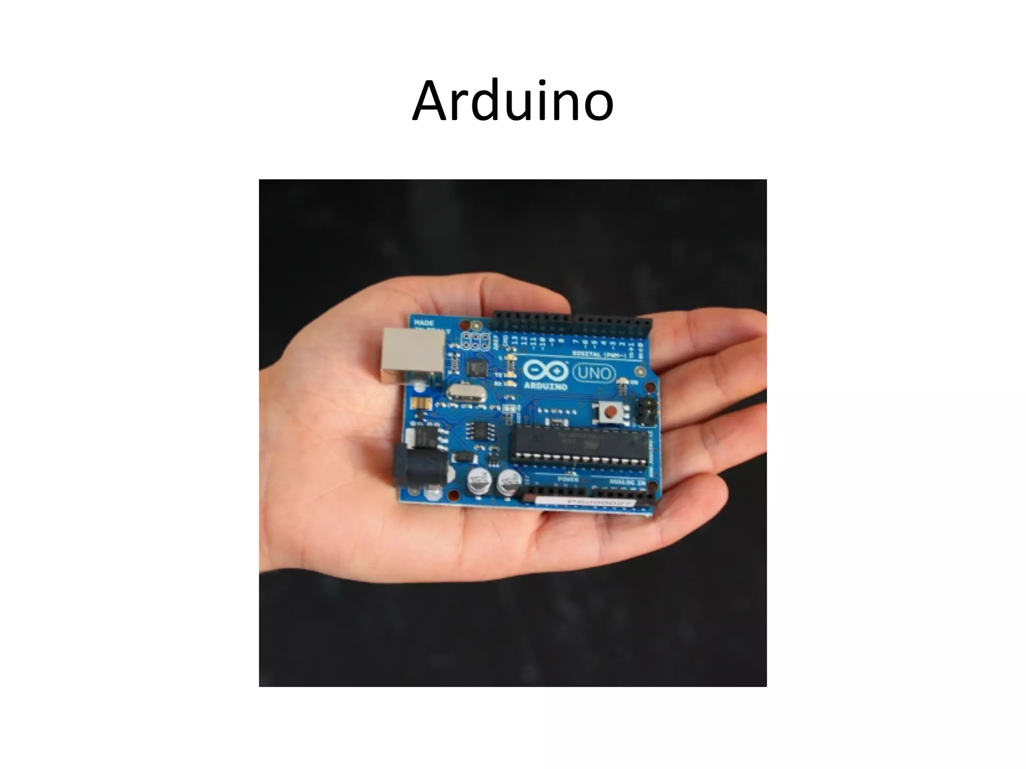
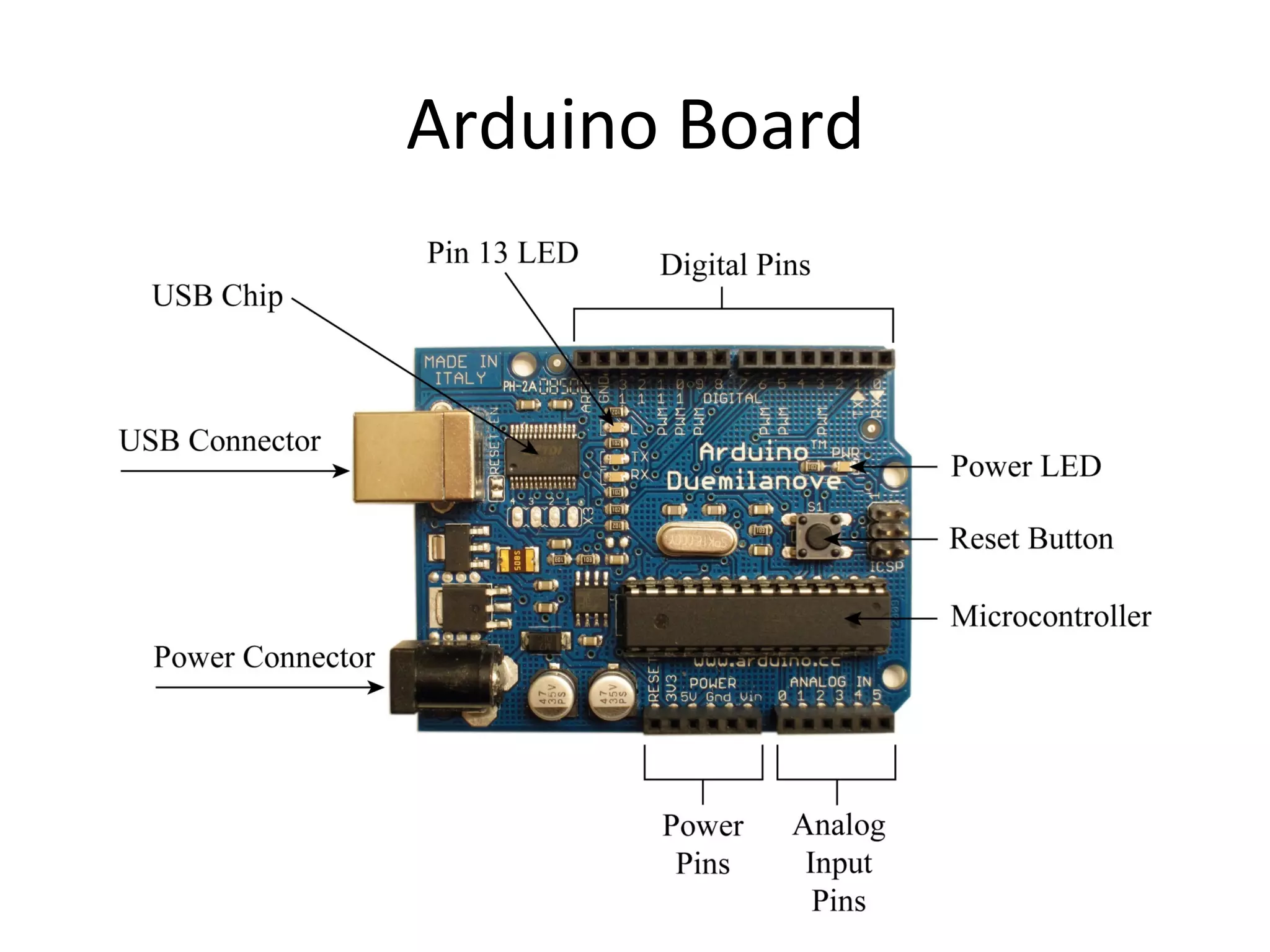
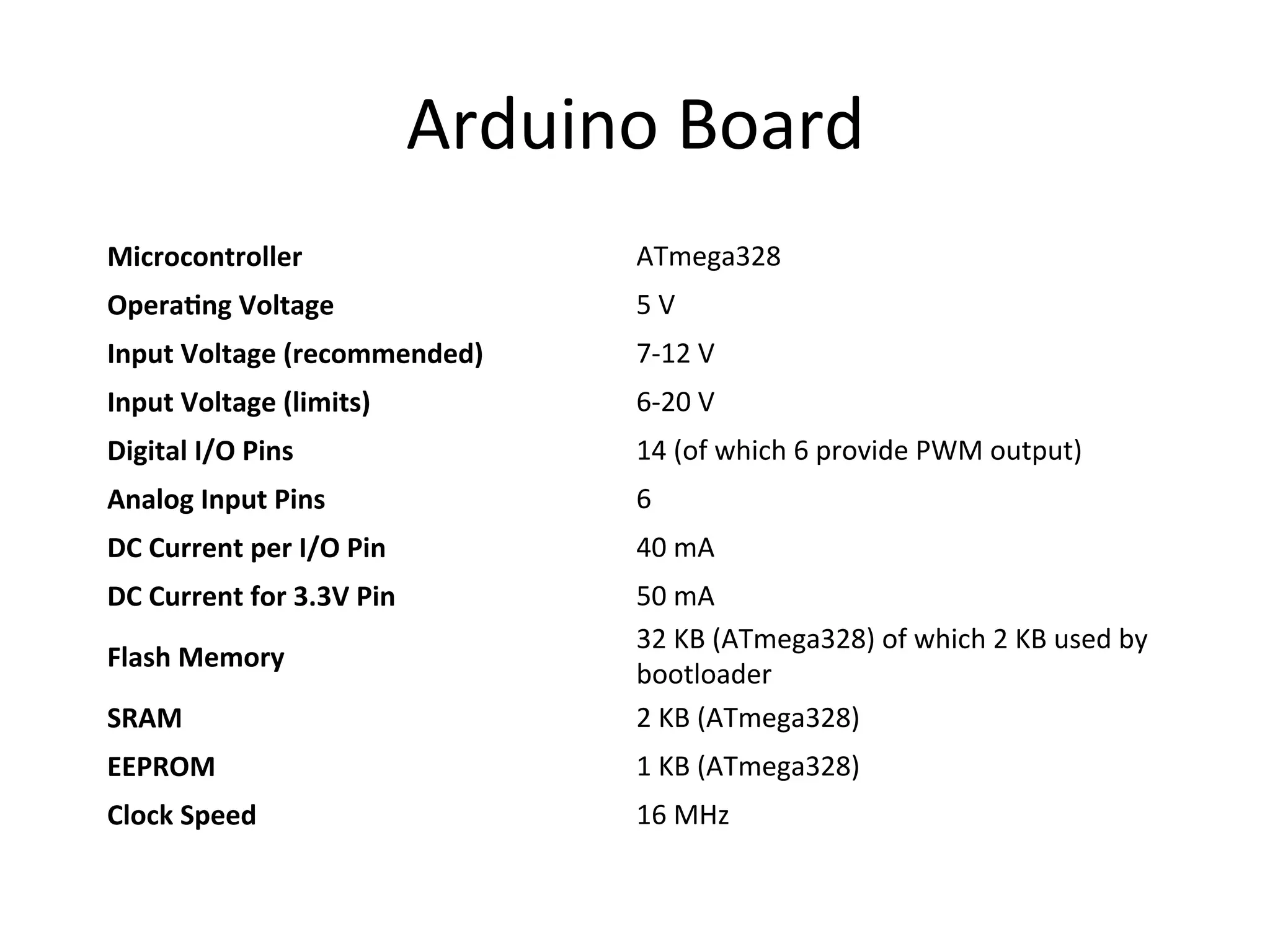
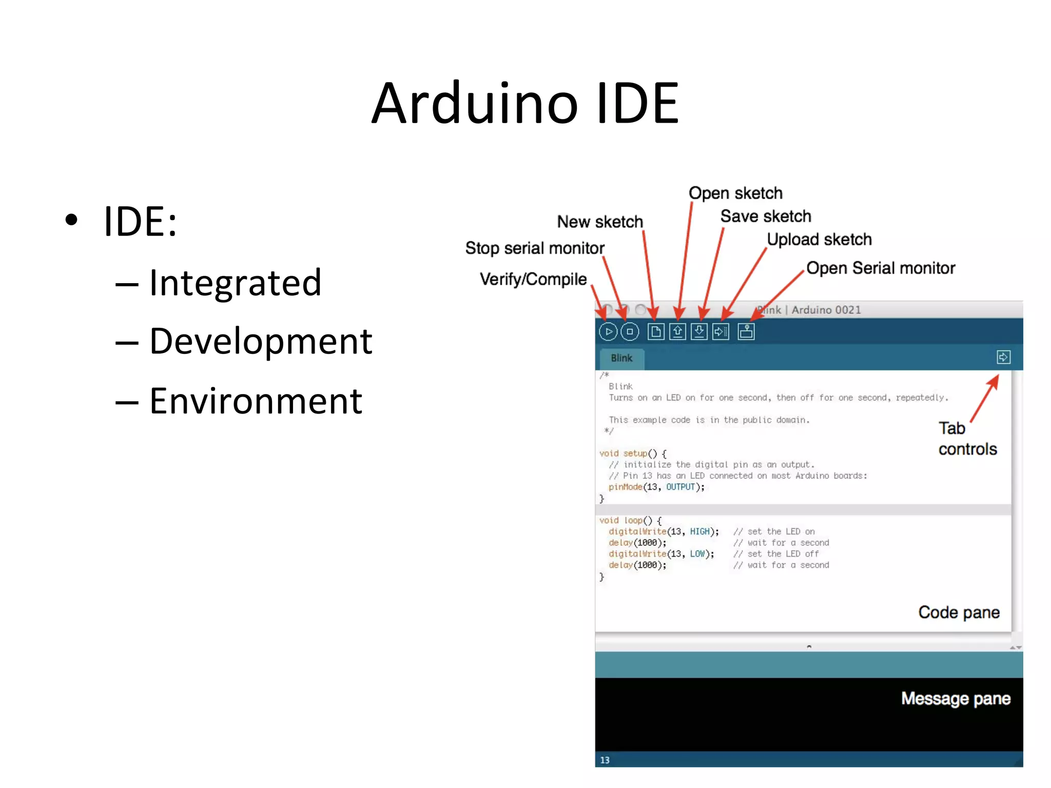
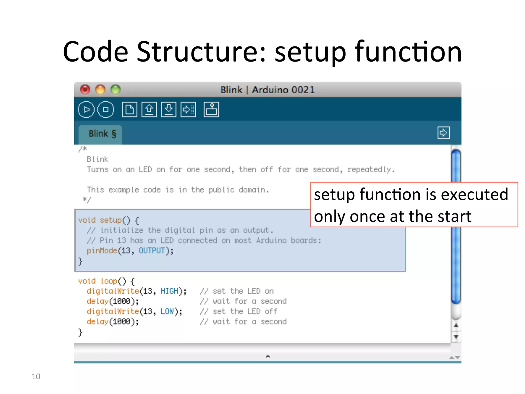
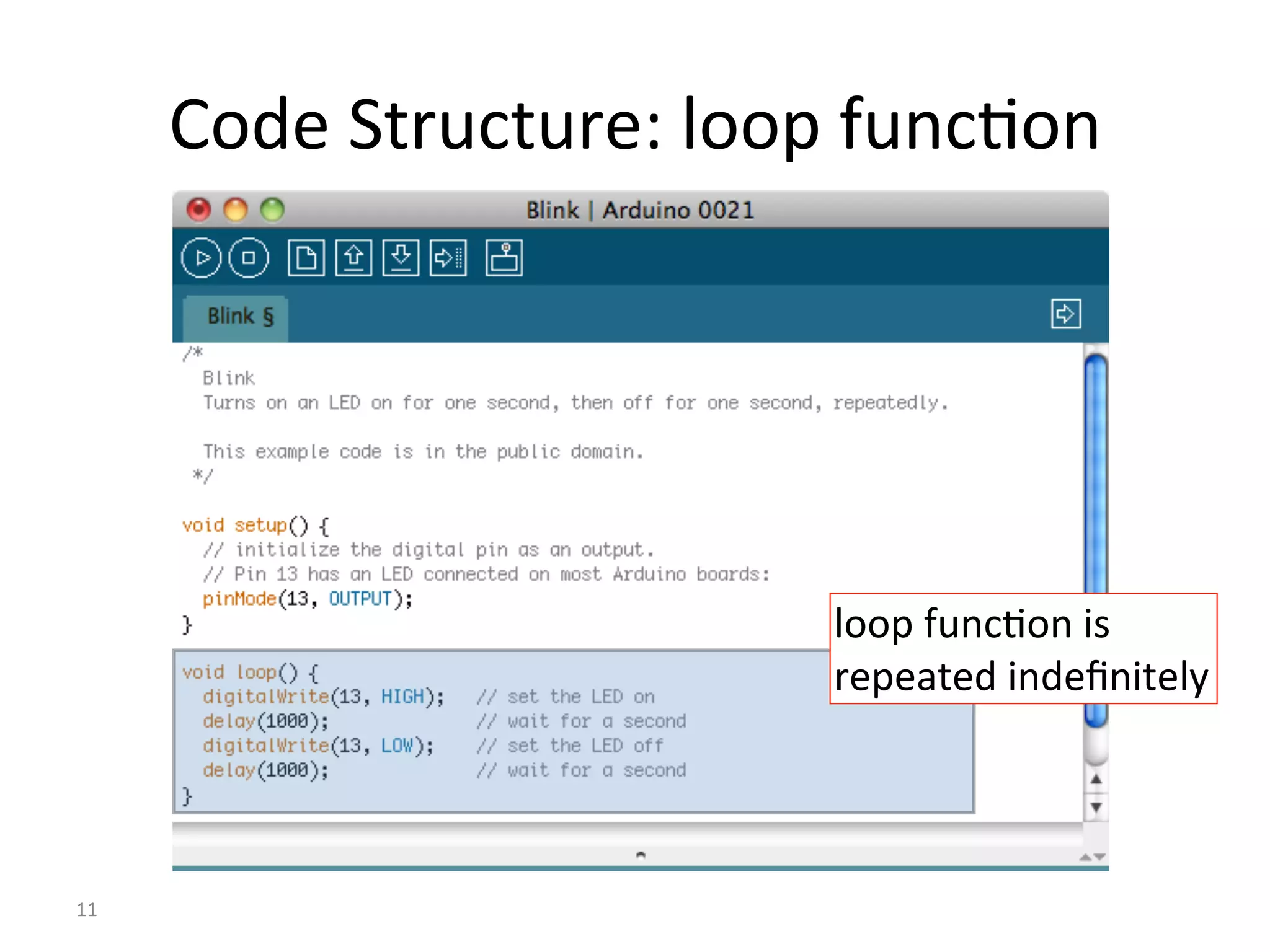
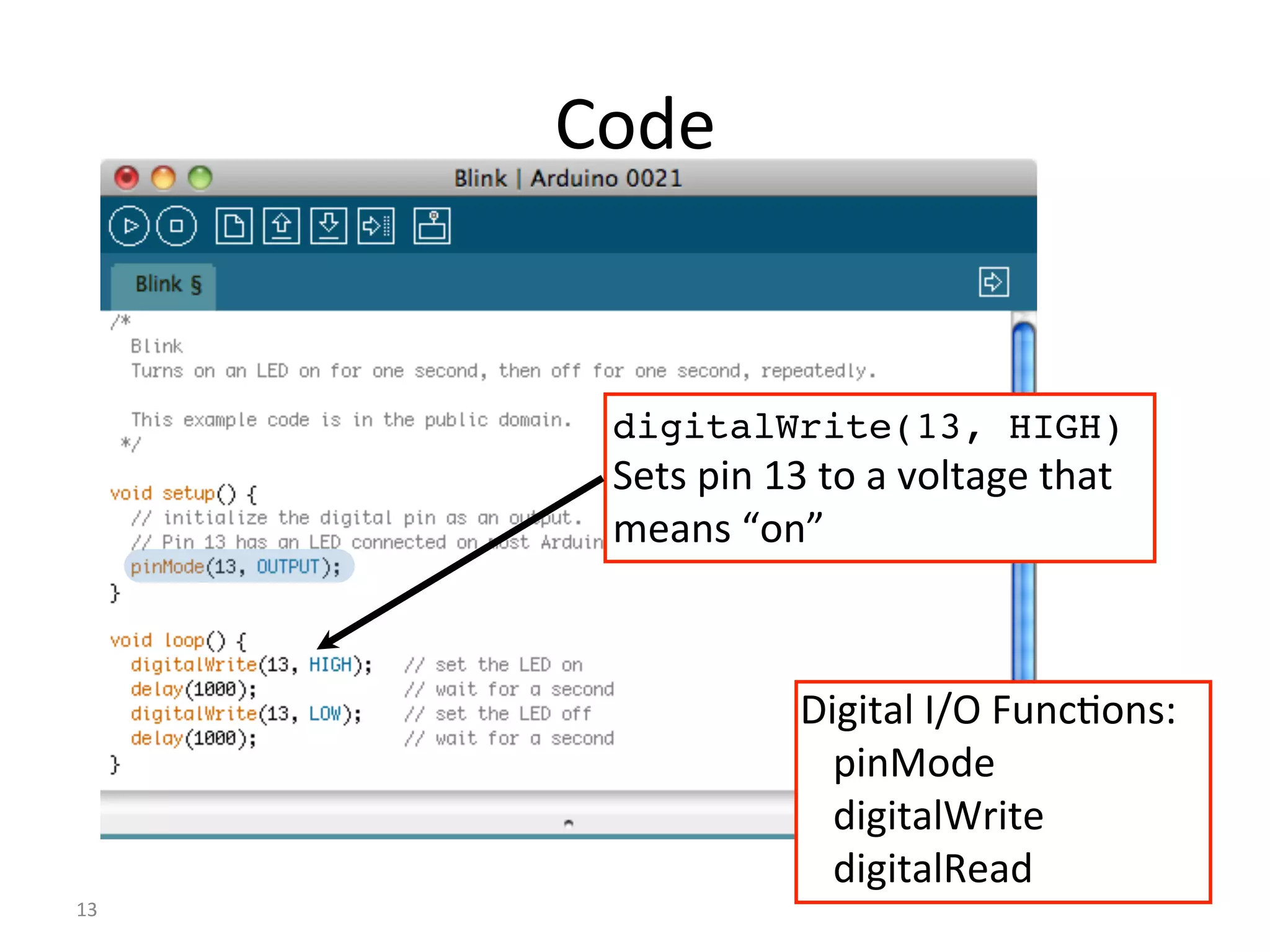
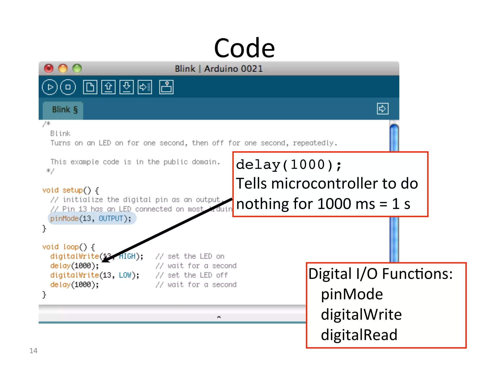
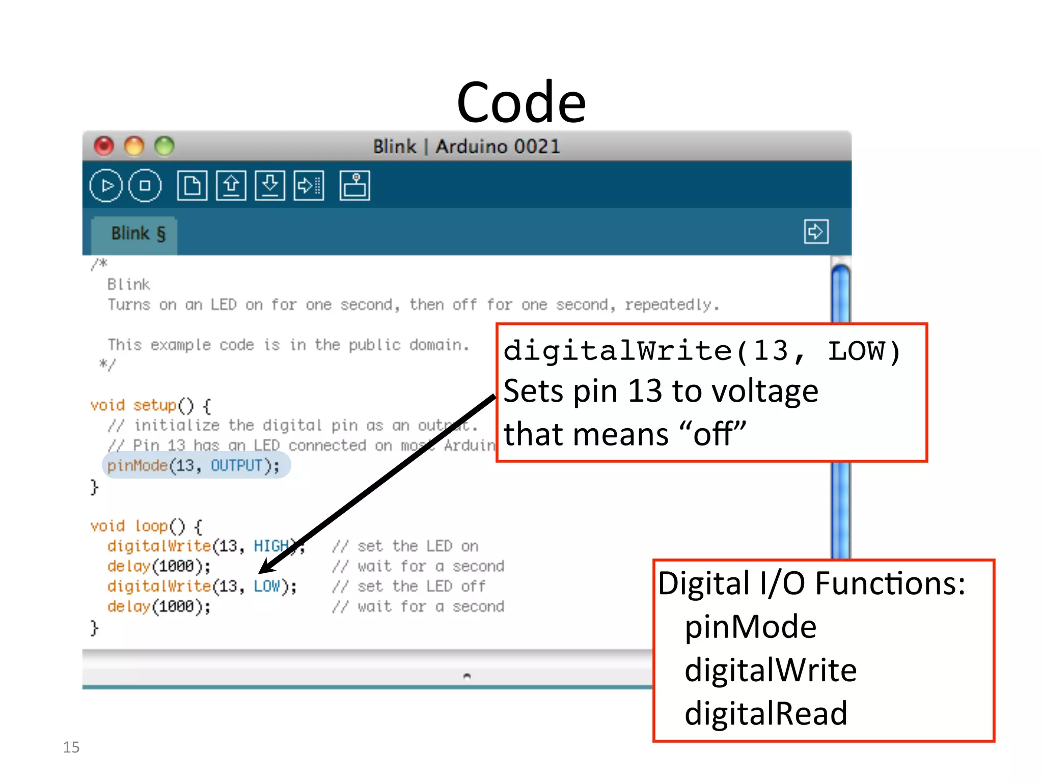
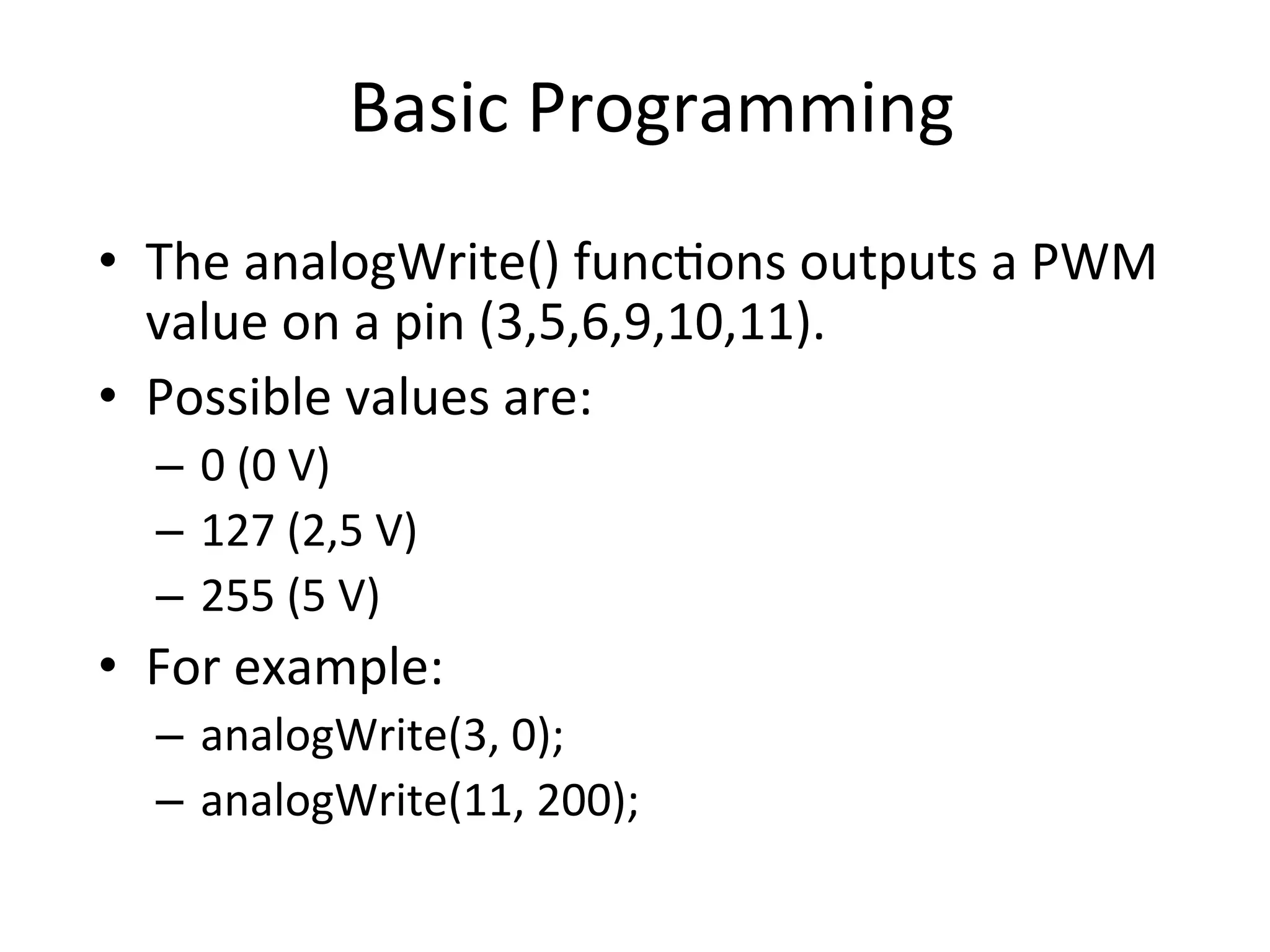
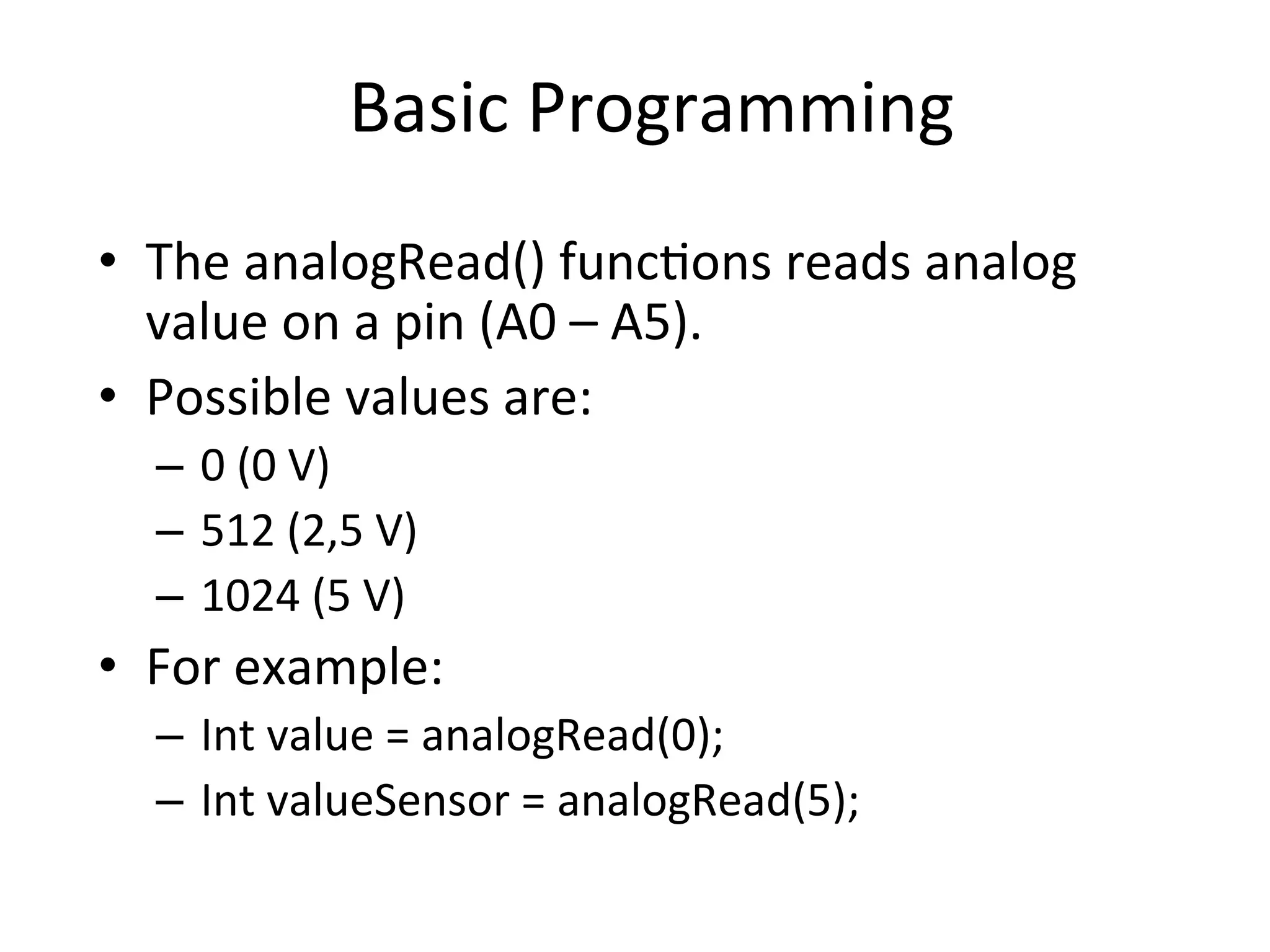
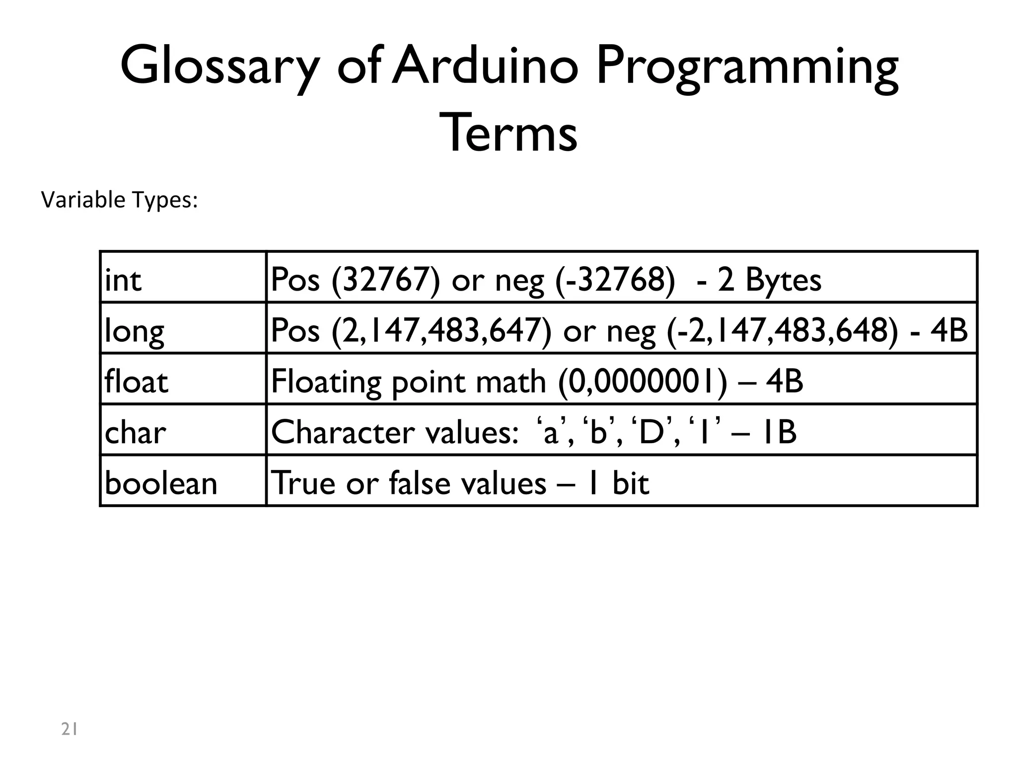
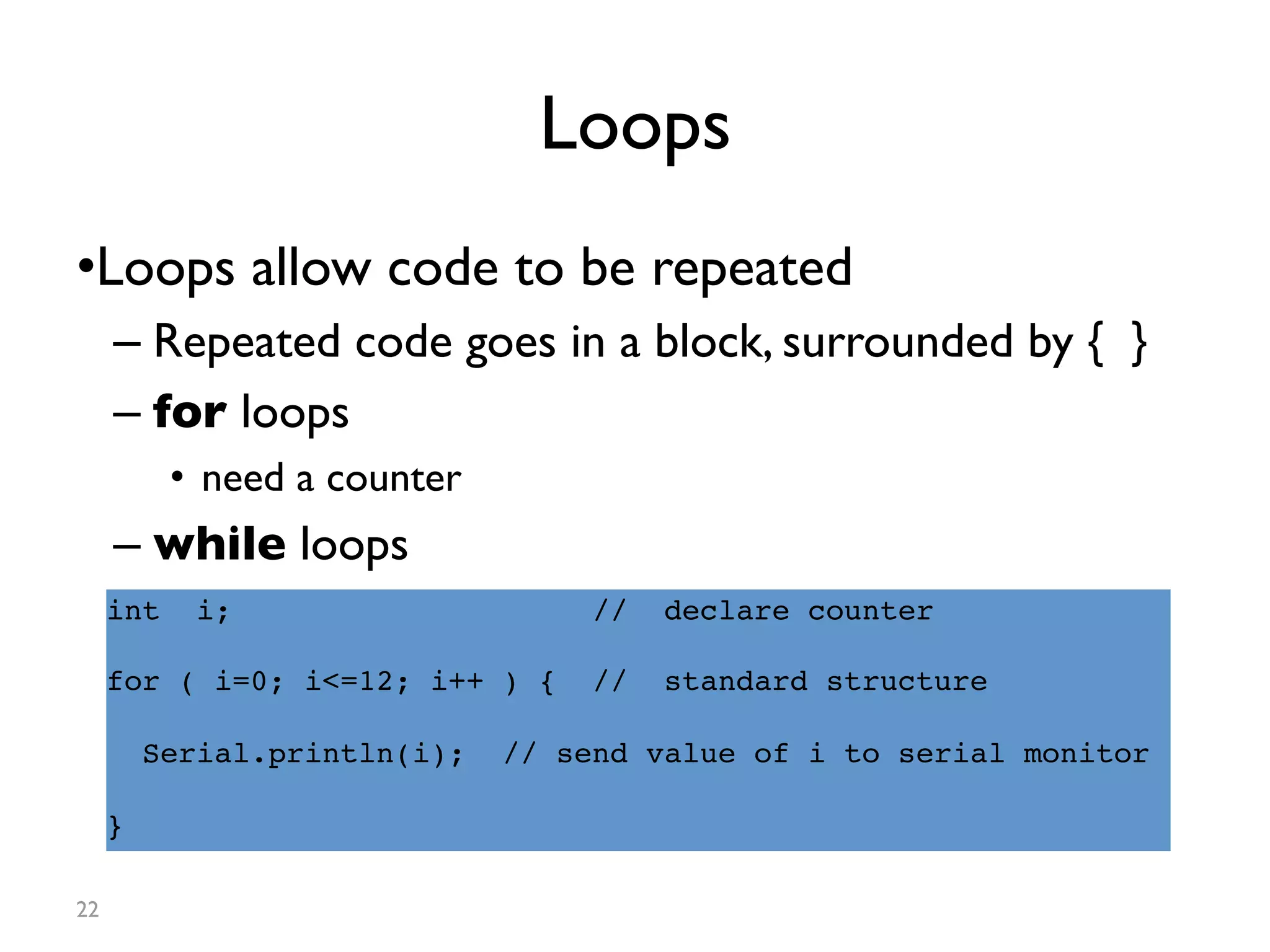
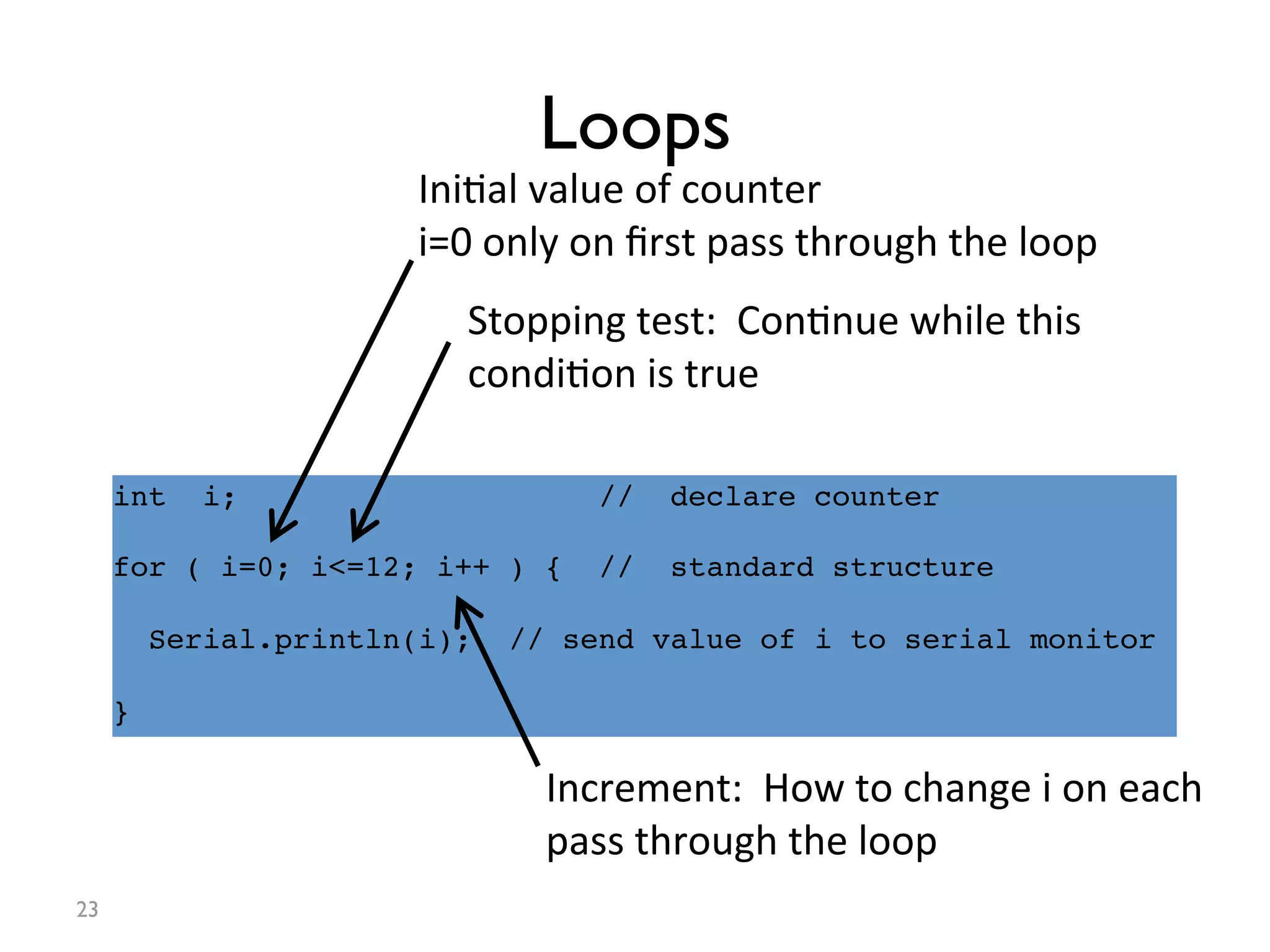
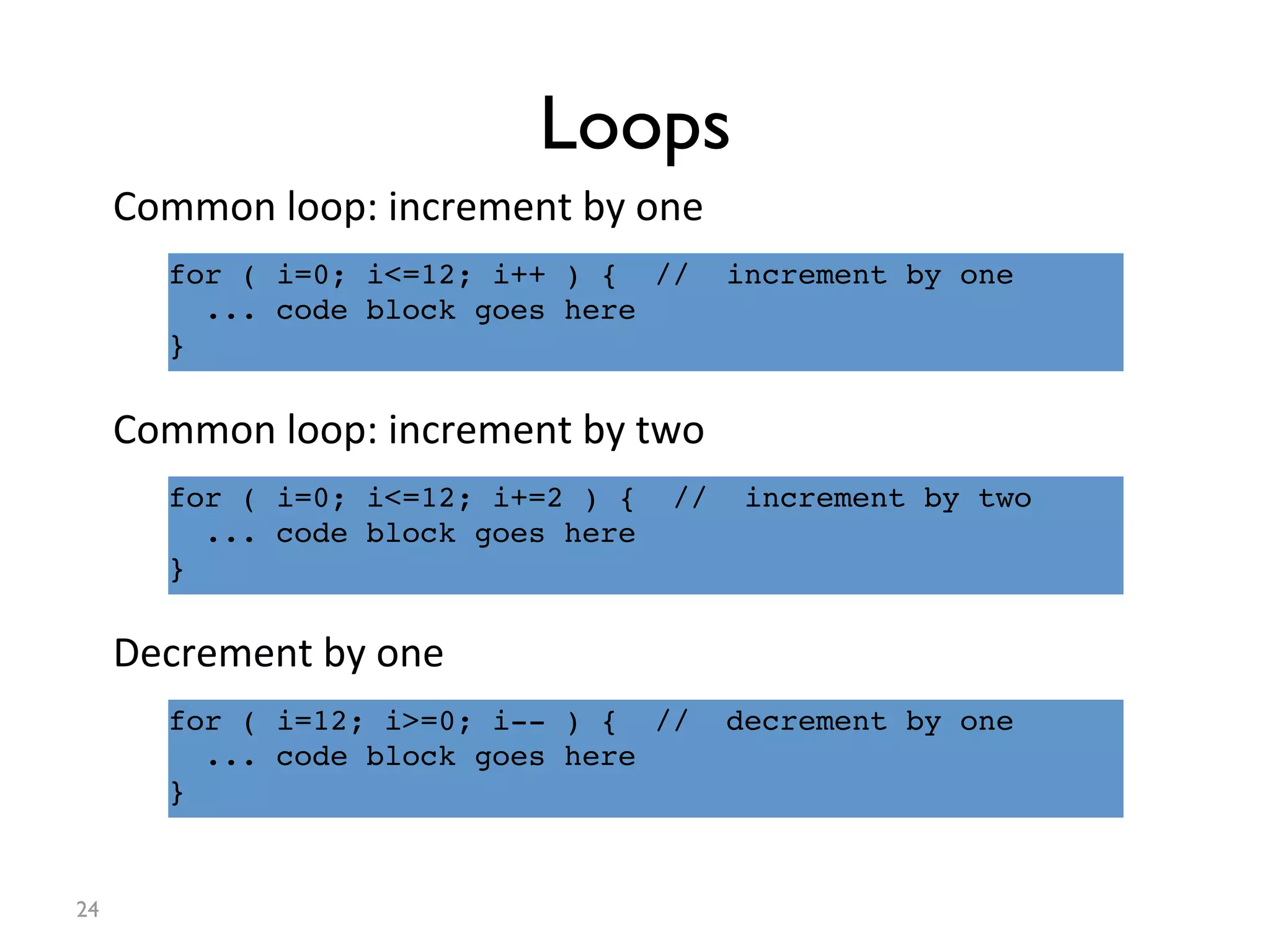
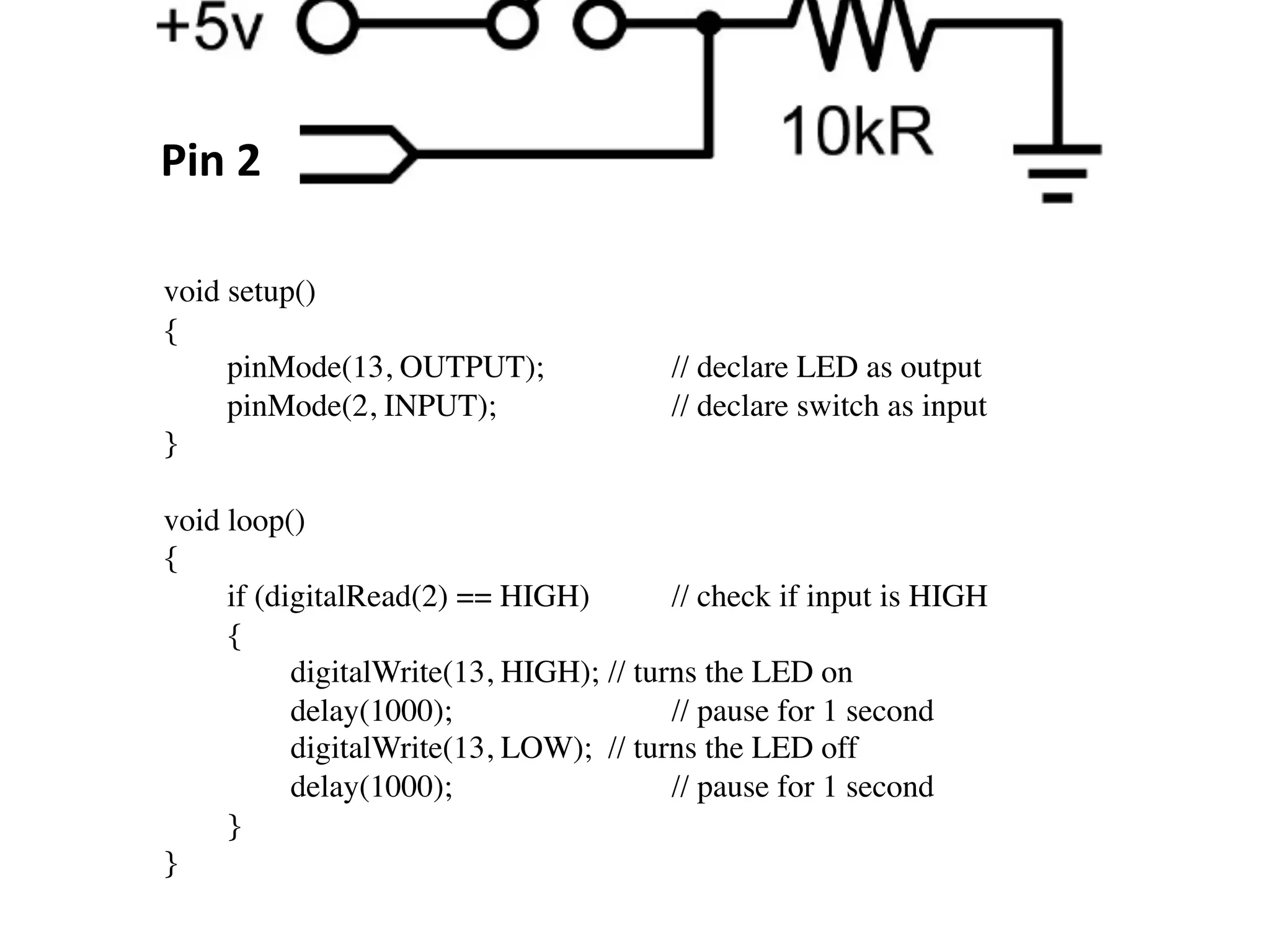
This document provides information about the Arduino workshop. It discusses Arduino boards and their components. It describes the Arduino IDE and basic code structure using functions like pinMode(), digitalWrite(), and delay(). It also explains programming concepts like variables, loops, and using sensors and actuators with digital and analog input/output pins.