Downloaded 37 times


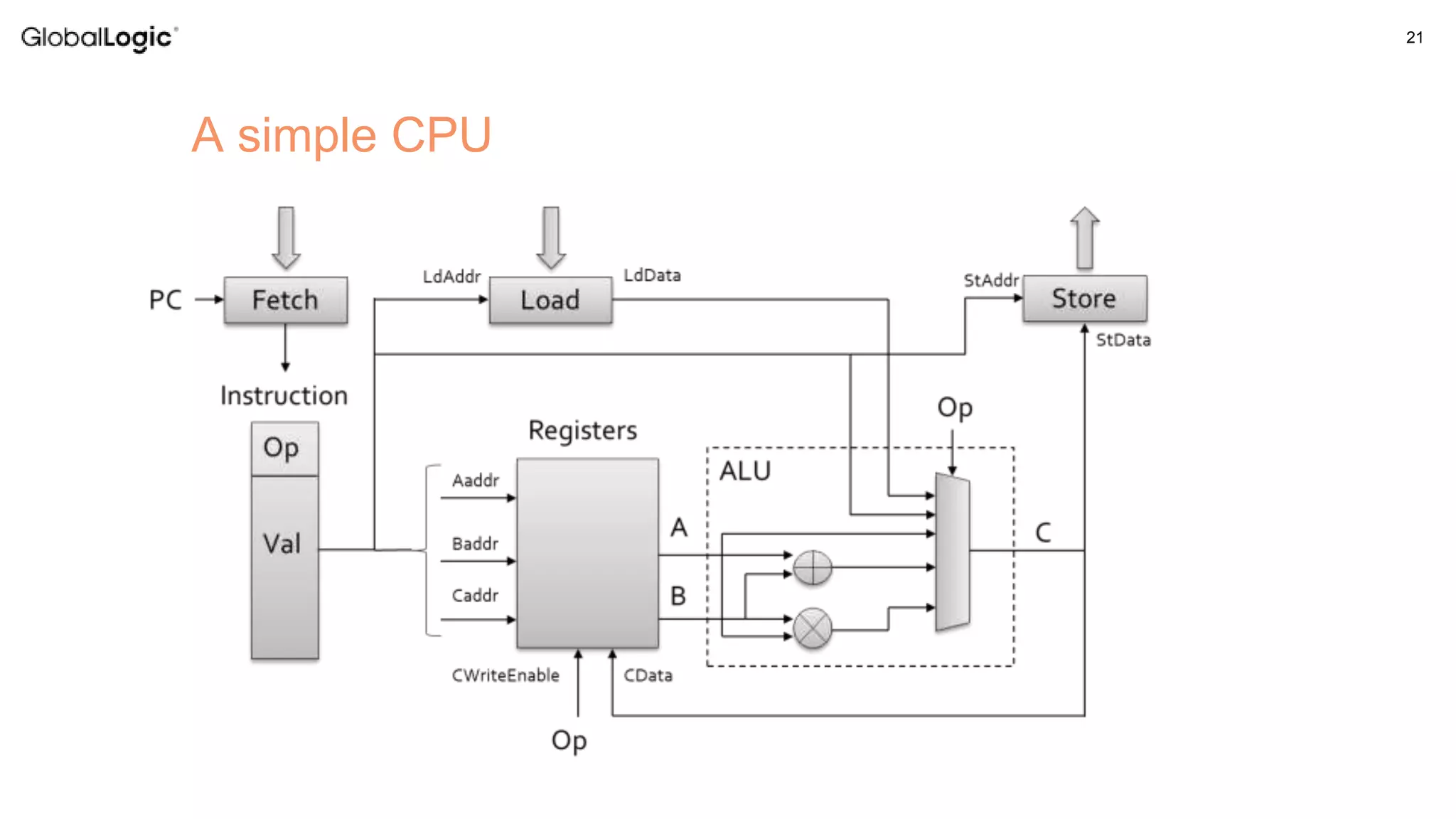
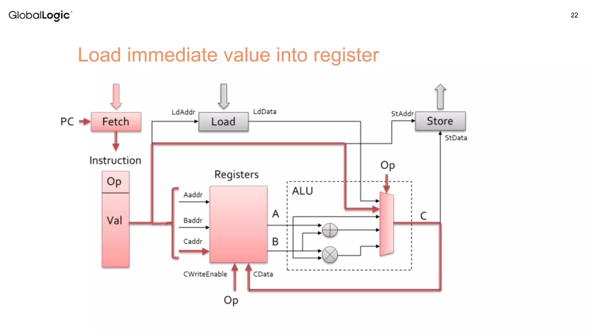
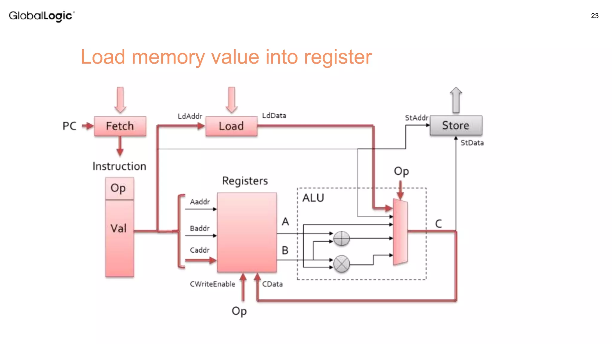
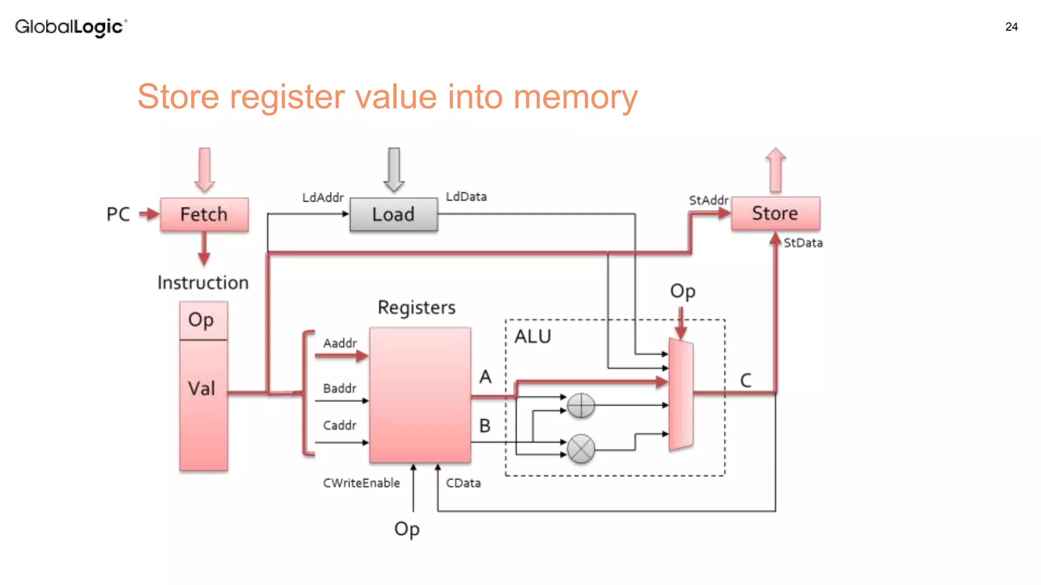
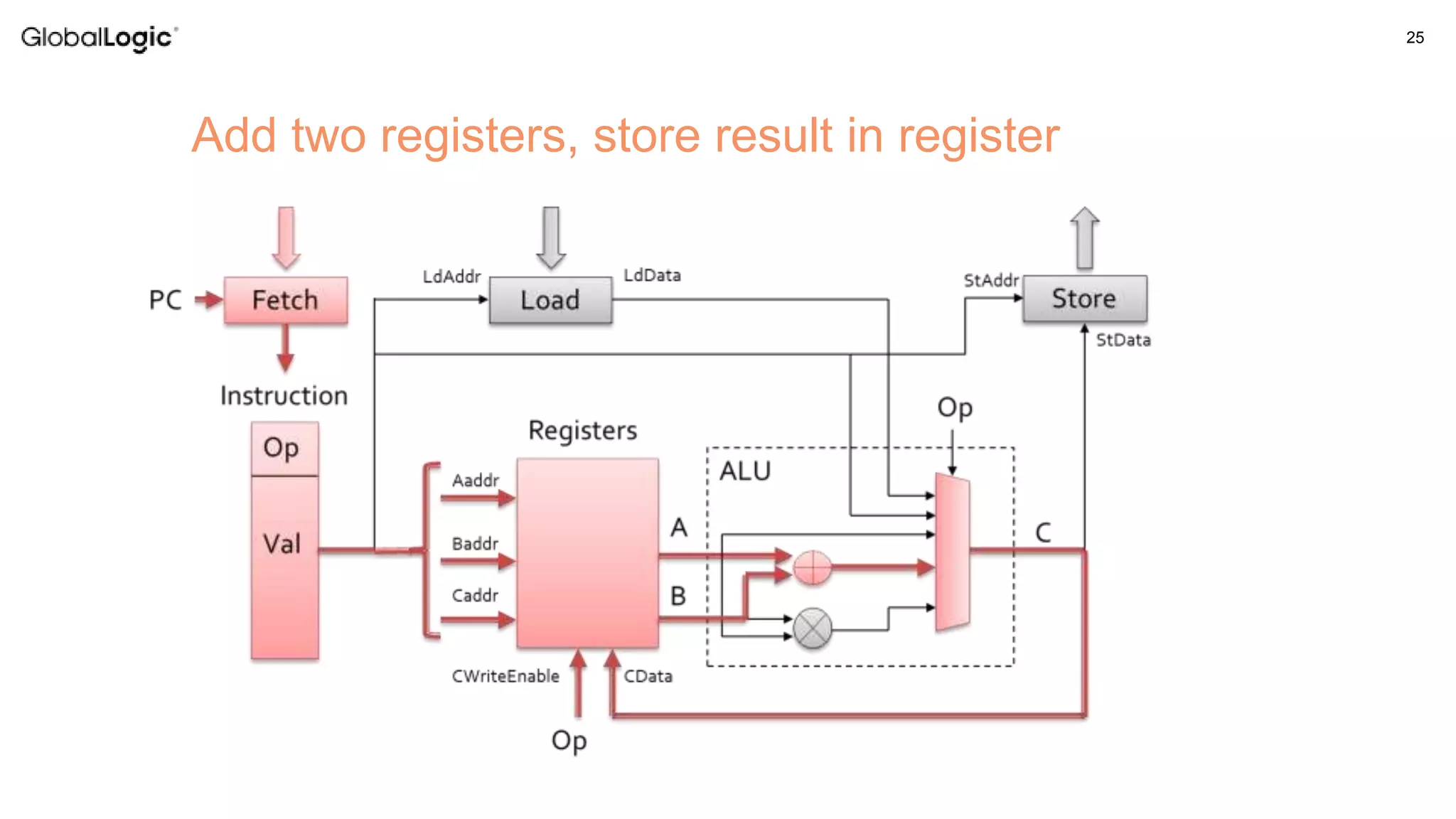
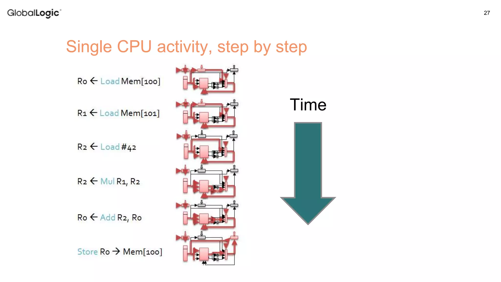
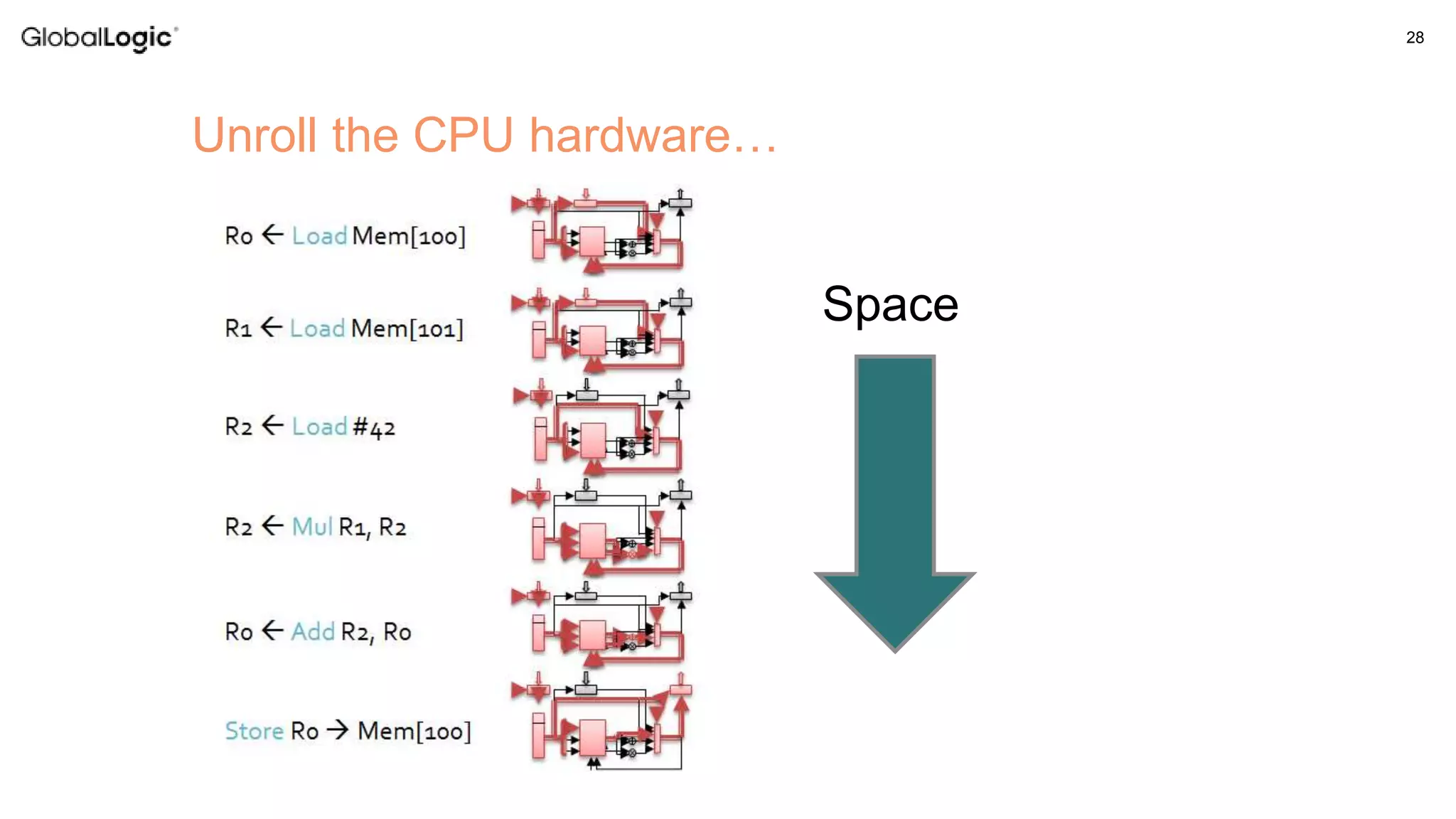
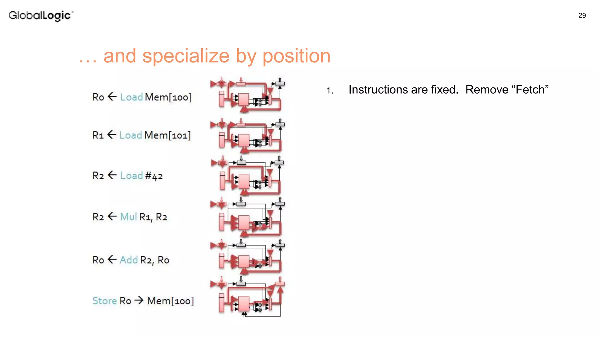
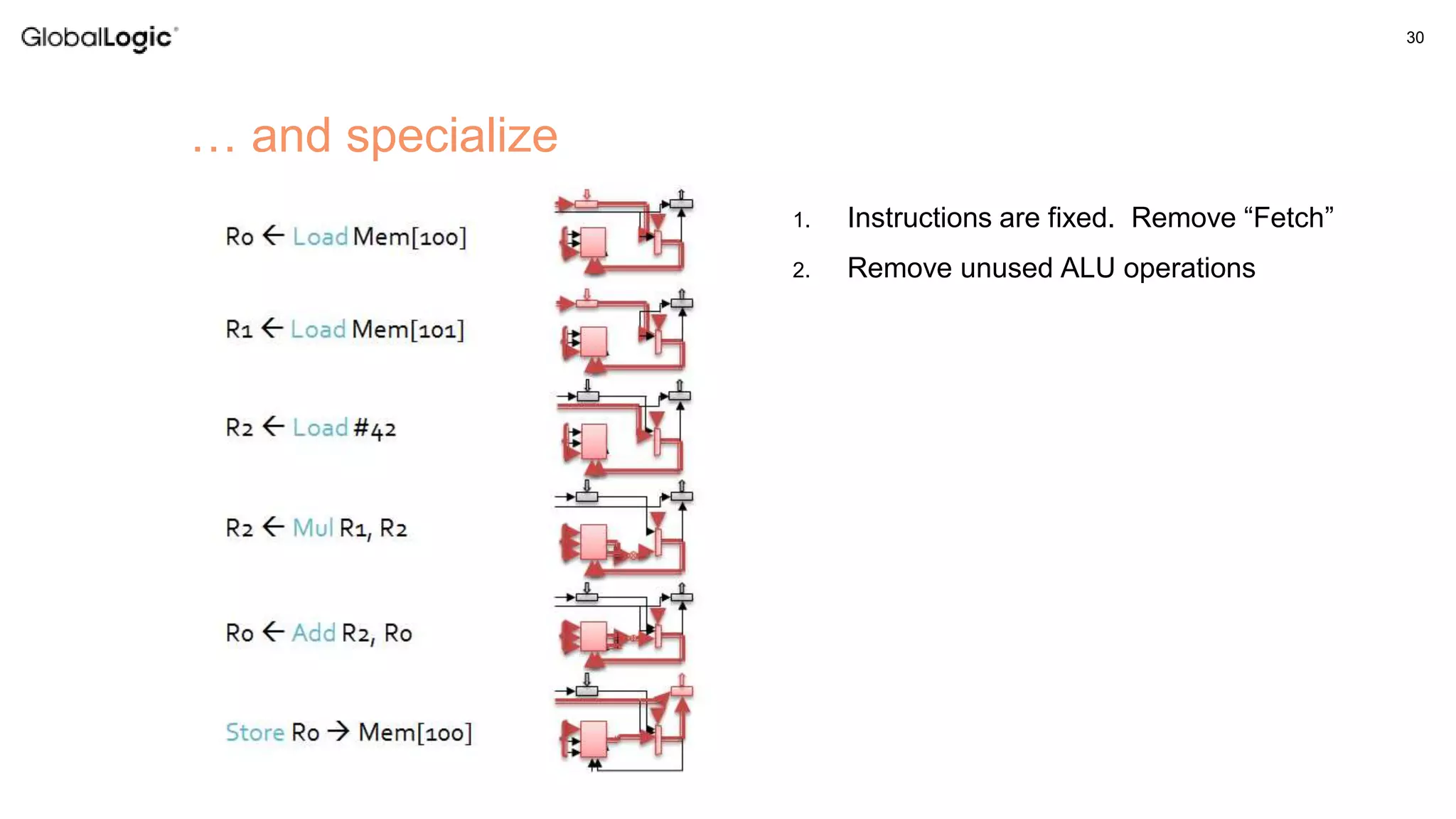
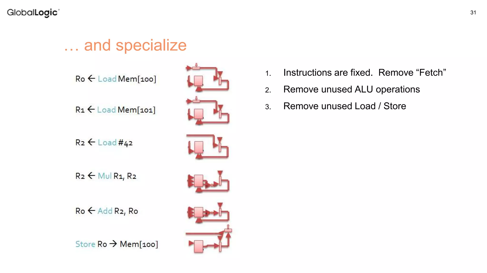
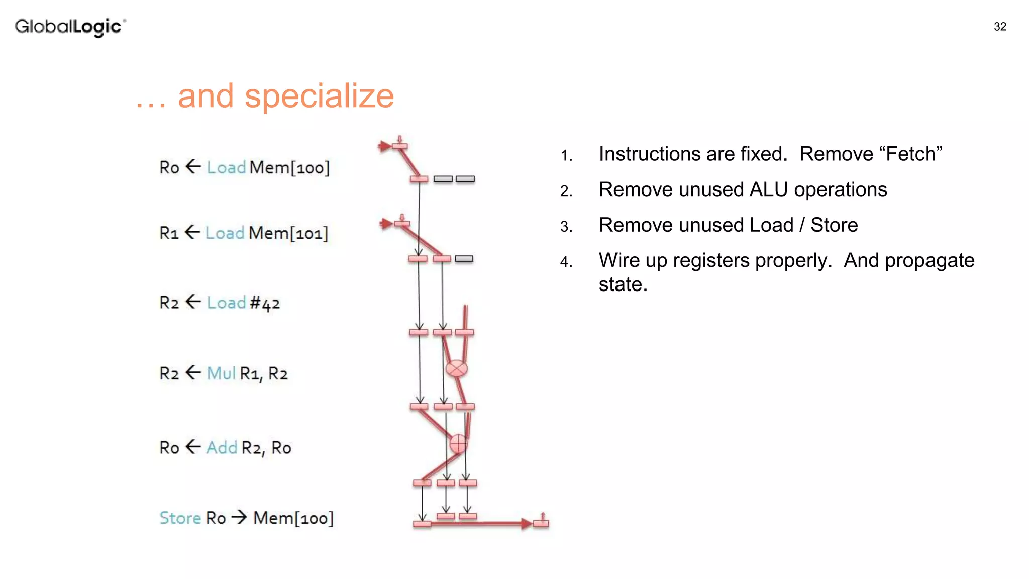
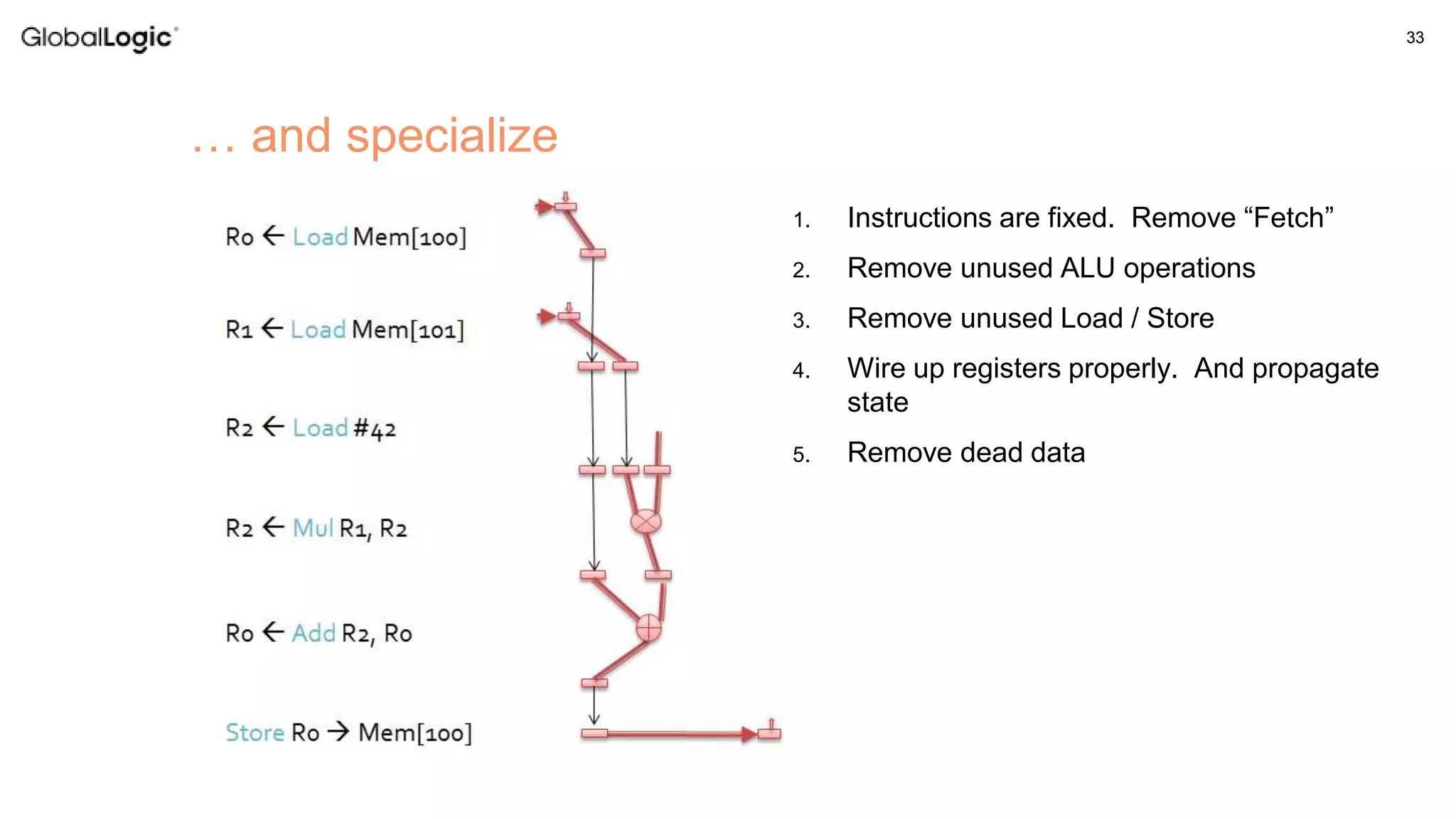
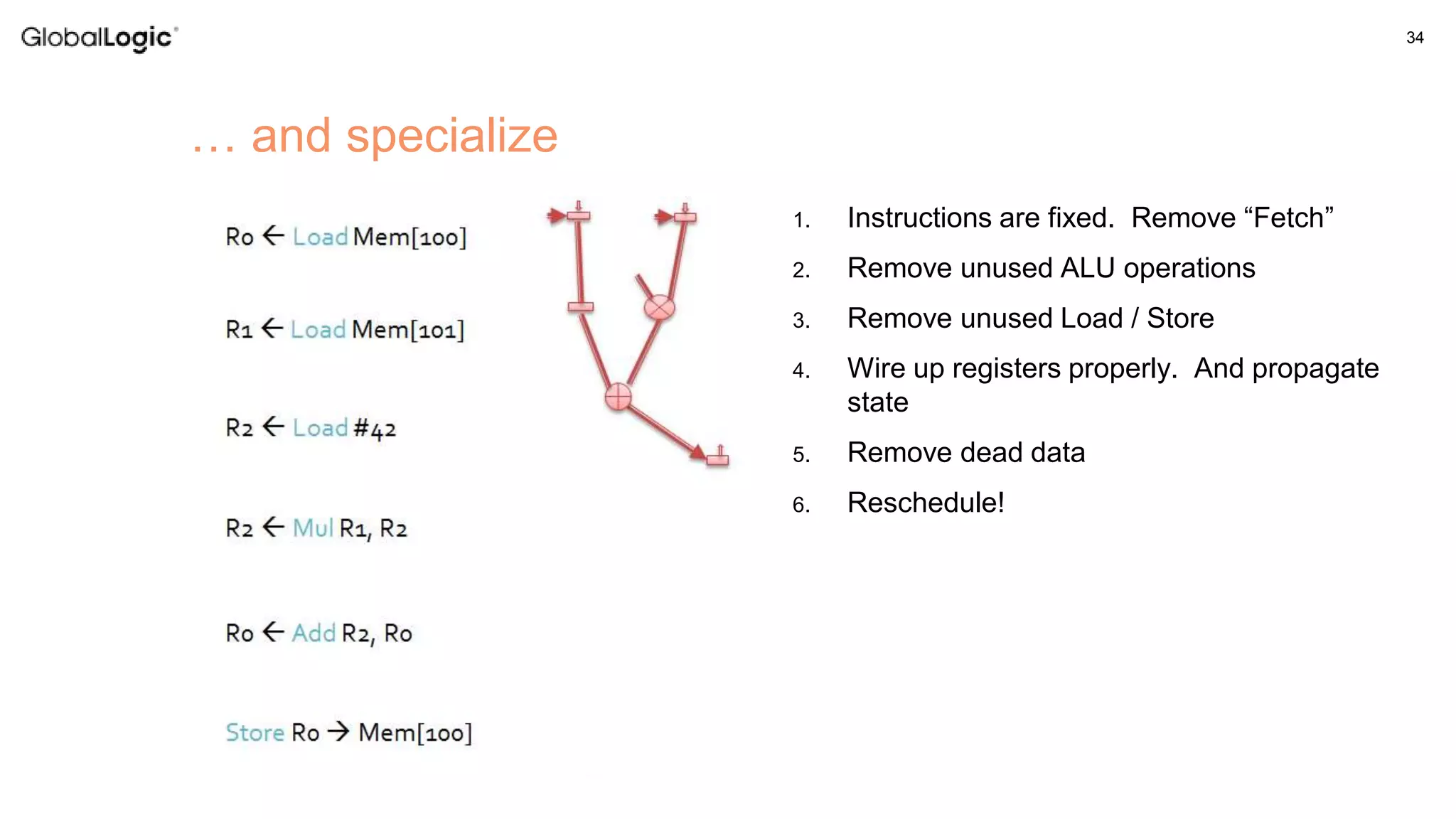
![26 A simple program Mem[100] += 42 * Mem[101] CPU instructions: R0 Load Mem[100] R1 Load Mem[101] R2 Load #42 R2 Mul R1, R2 R0 Add R2, R0 Store R0 Mem[100]](https://image.slidesharecdn.com/fpgainembeddeddevices-170410093652/75/Using-FPGA-in-Embedded-Devices-26-2048.jpg)
![36 OpenCL FPGA • Host + Accelerator Programming Model • Sequential Host program on microprocessor • Function offload onto a highly parallel accelerator device main() { read_data( … ); maninpulate( … ); clEnqueueWriteBuffer( … ); clEnqueueNDRange(…,sum,…); clEnqueueReadBuffer( … ); display_result( … ); } __kernel void sum(__global float *a, __global float *b, __global float *y) { int gid = get_global_id(0); y[gid] = a[gid] + b[gid]; } Host Code FPGA Design User Application Algorithm](https://image.slidesharecdn.com/fpgainembeddeddevices-170410093652/75/Using-FPGA-in-Embedded-Devices-36-2048.jpg)
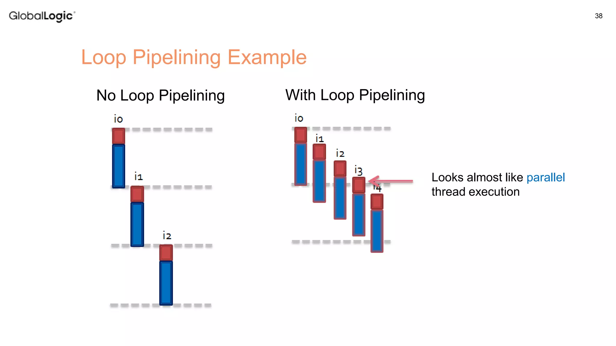
![37 Loop Pipelining • Analyze any dependencies between iterations • Schedule these operations • Launch the next iteration as soon as possible float array[M]; for (int i=0; i < n*numSets; i++) { for (int j=0; j < M-1; j++) array[j] = array[j+1]; array[M-1] = a[i]; for (int j=0; j < M; j++) answer[i] += array[j] * coefs[j]; } At this point, we can launch the next iteration](https://image.slidesharecdn.com/fpgainembeddeddevices-170410093652/75/Using-FPGA-in-Embedded-Devices-37-2048.jpg)


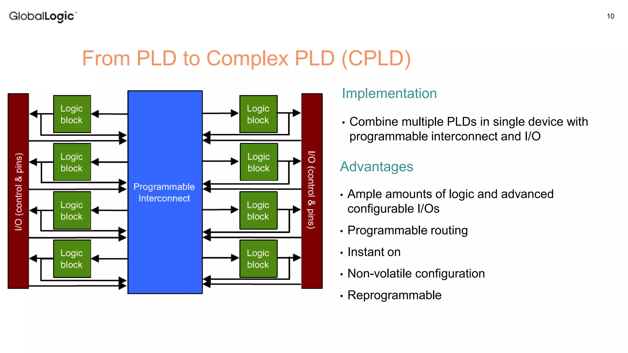
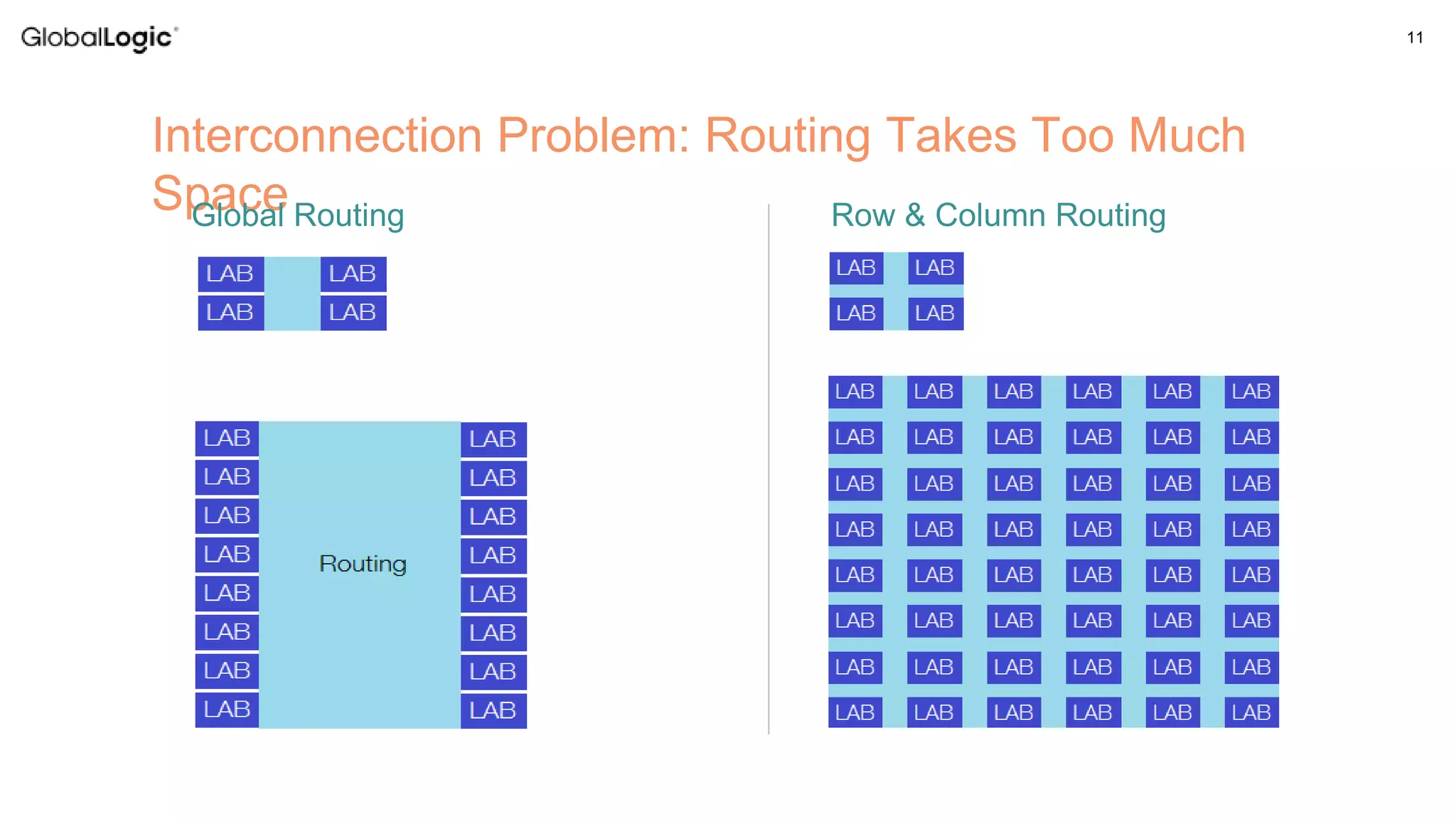
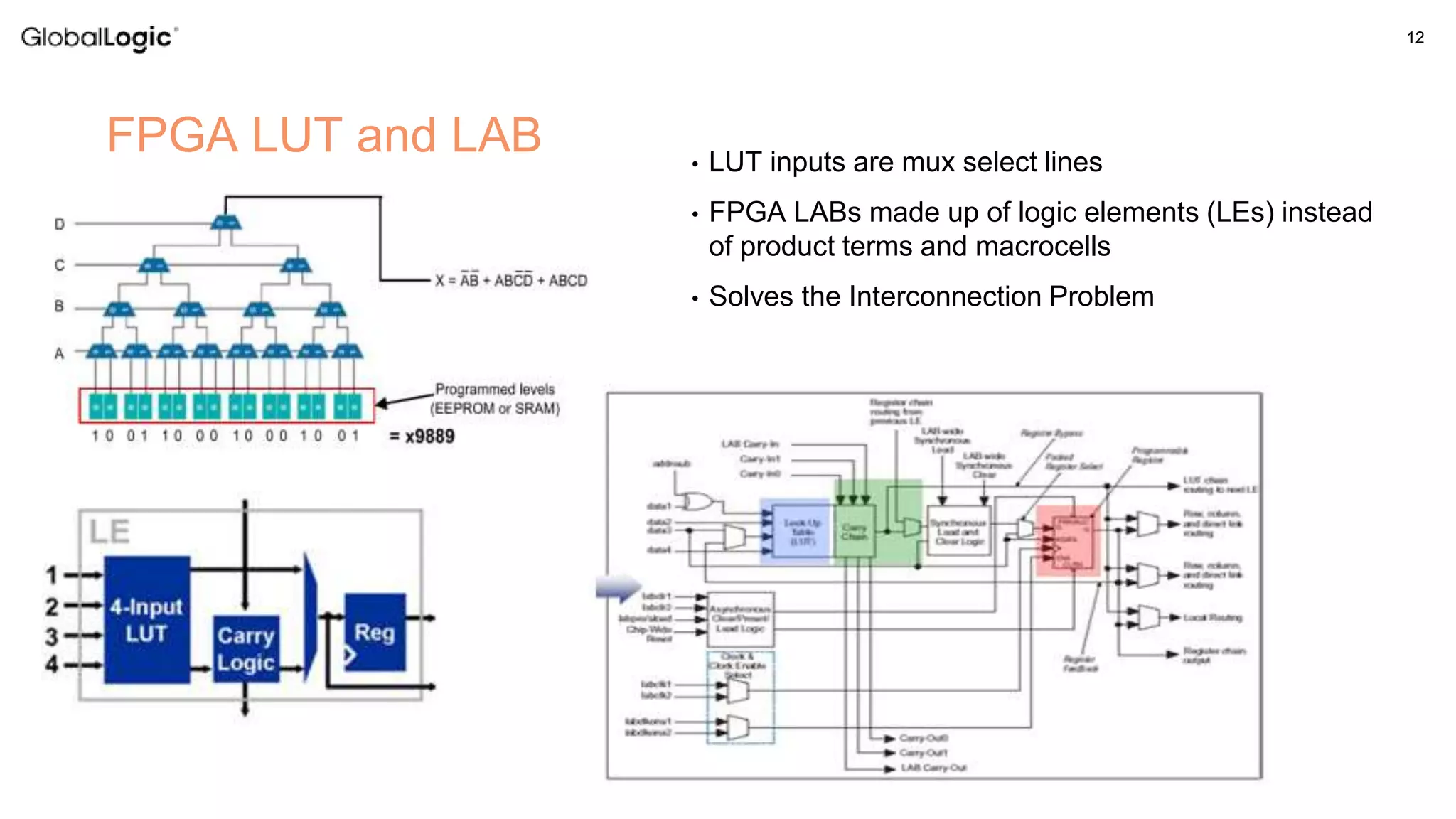
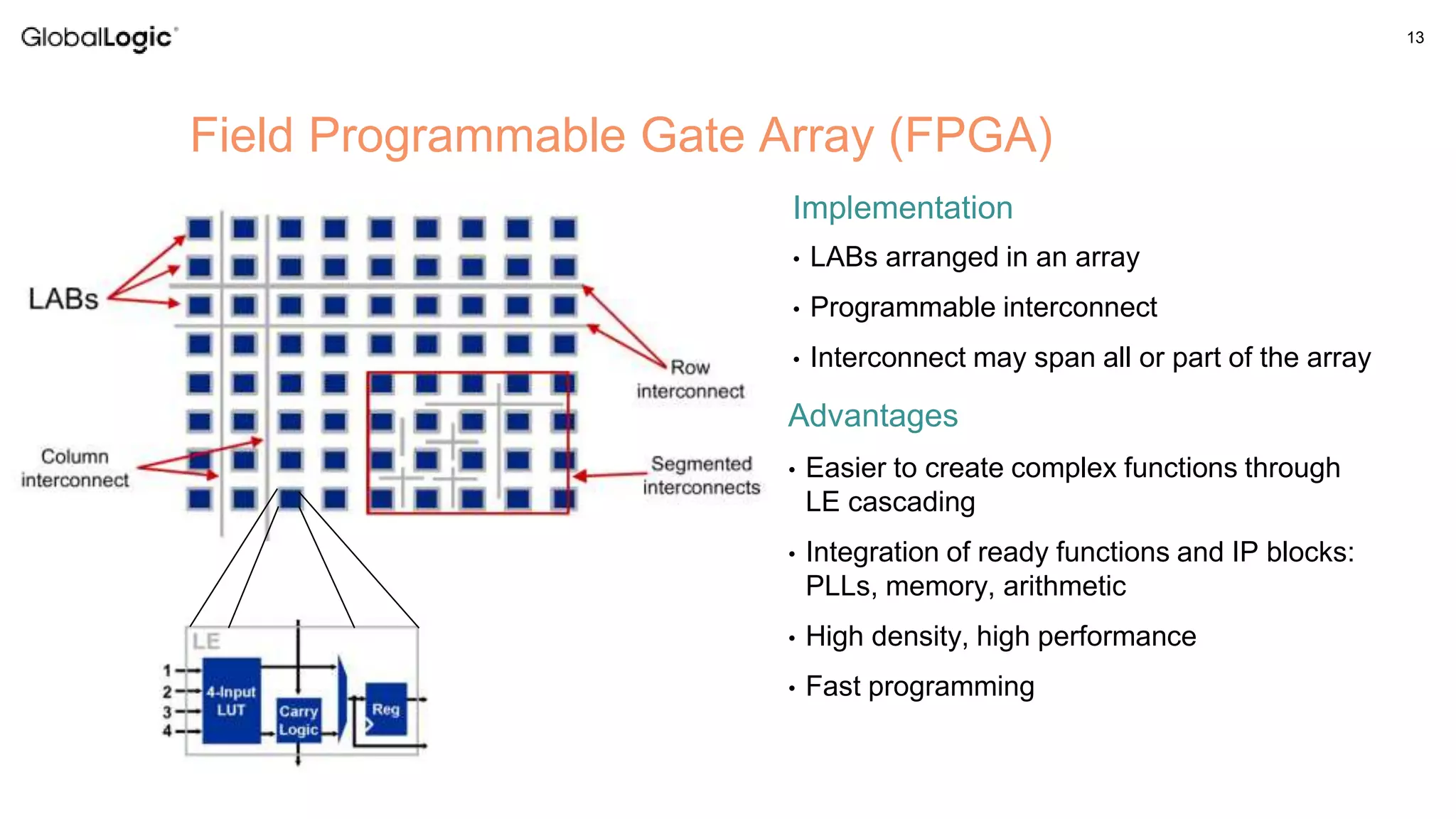
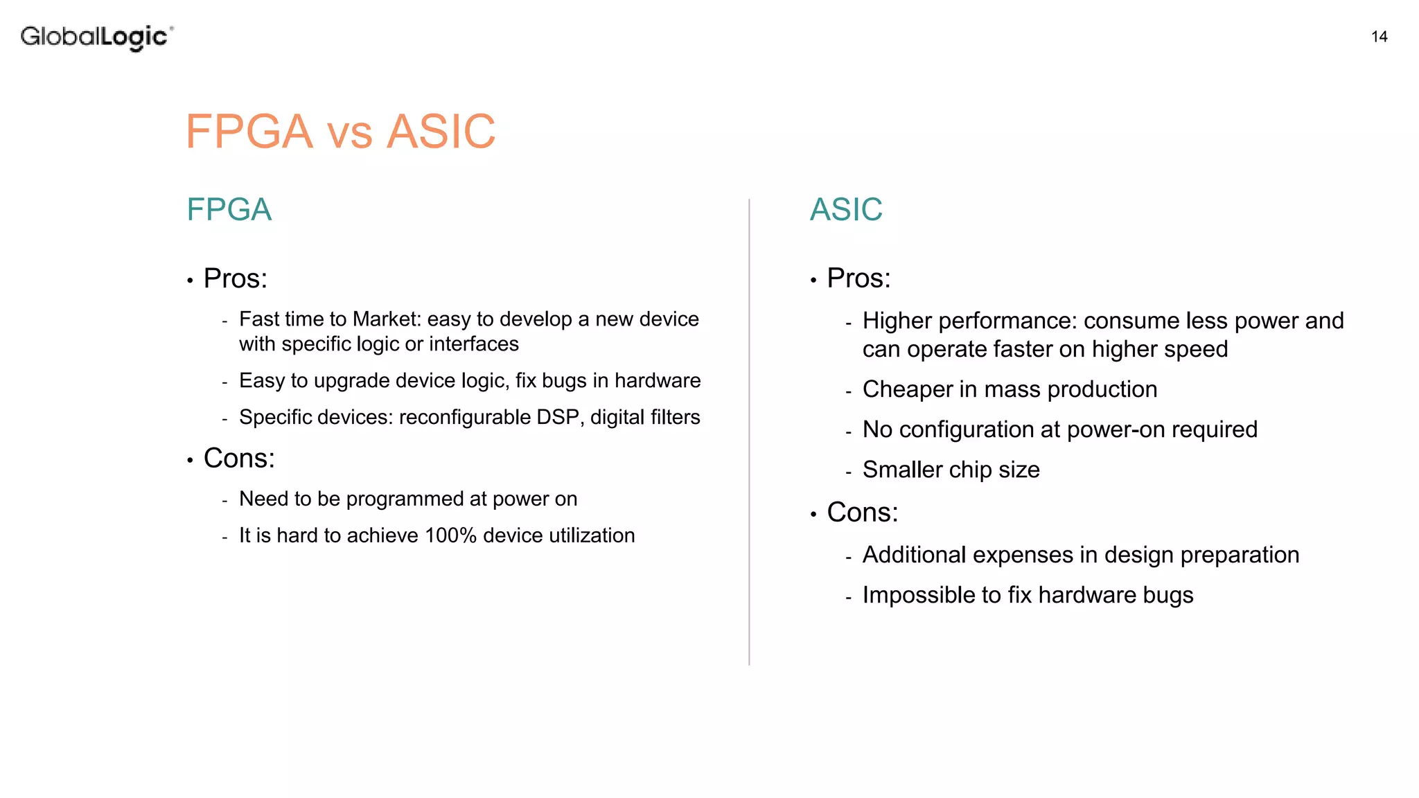
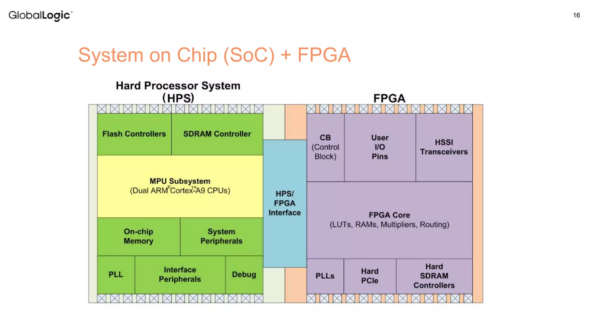
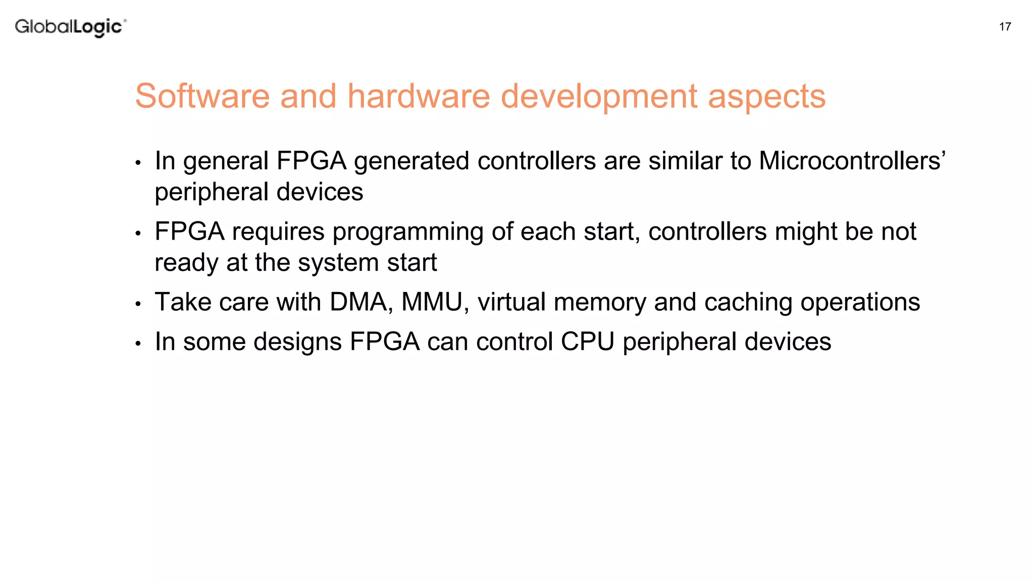
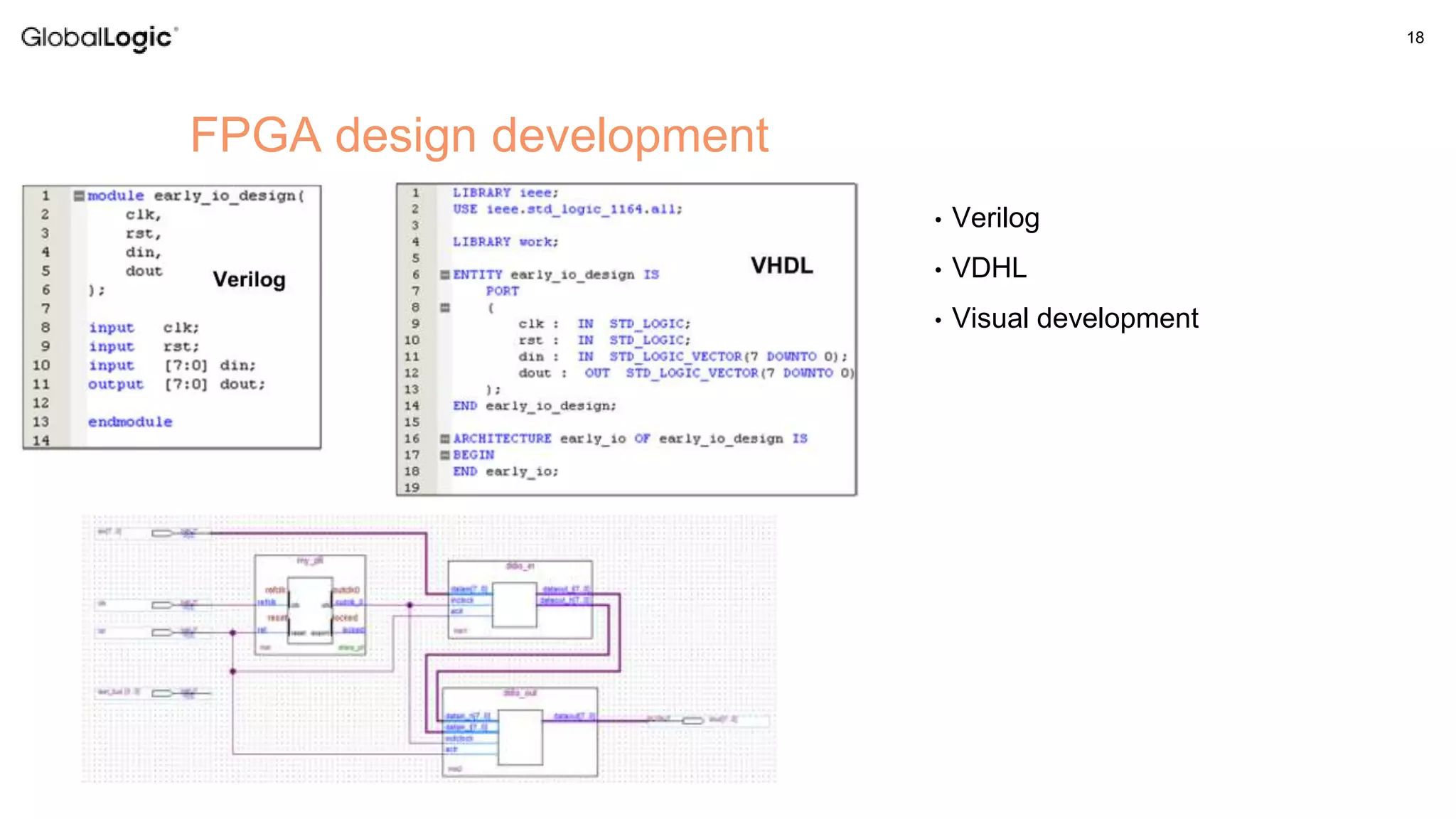
The document discusses the use of FPGAs in embedded devices, outlining their advantages over traditional logic devices like ASICs, including faster time to market and ease of upgrades. It covers the architecture of FPGAs, the programming aspects with languages such as Verilog and VHDL, and applications like high-speed data processing using OpenCL. Additionally, the document highlights design considerations and techniques for efficient FPGA utilization in embedded systems.