The document presents a workshop on building a Raspberry Pi game console, detailing the introduction to GPIO (General Purpose Input/Output) programming, circuit fundamentals, and practical projects. It includes step-by-step instructions for environment setup, coding examples in Python, and various projects like LED blinking and traffic light simulation. Additionally, it covers concepts such as event-driven programming, button inputs, and circuit design, aiming to equip participants with the skills to create their own hardware projects using Raspberry Pi.


![21 ● Dynamic typing # This is a comment i = 3 # assign 3 to variable i i = [1, 2, 3, 4, 5] # assign a list to i print(i[2]) # print the 3rd element i = "abcde" # assign a string to i print(i[2]) # print the 3rd character Variable, Object, Type, Comment](https://image.slidesharecdn.com/raspberry-pi-gpio-tutorial-en-190902223232/75/Raspberry-Pi-GPIO-Tutorial-Make-Your-Own-Game-Console-21-2048.jpg)
![24 ● Iterator for i in range(start, stop[, step]): process for i in range(0, 11, 5): print(i) Loop](https://image.slidesharecdn.com/raspberry-pi-gpio-tutorial-en-190902223232/75/Raspberry-Pi-GPIO-Tutorial-Make-Your-Own-Game-Console-24-2048.jpg)
![27 ● 1. Execute the script file ● $ nano test.py ● $ python3 test.py ● 2. Execute interactively ● $ python3 Python 3.5.3 (default, Sep 27 2018, 17:25:39) ● [GCC 6.3.0 20170516] on linux Type "help", "copyright", "credits" or "license" for more information. >>> Execution Modes](https://image.slidesharecdn.com/raspberry-pi-gpio-tutorial-en-190902223232/75/Raspberry-Pi-GPIO-Tutorial-Make-Your-Own-Game-Console-27-2048.jpg)


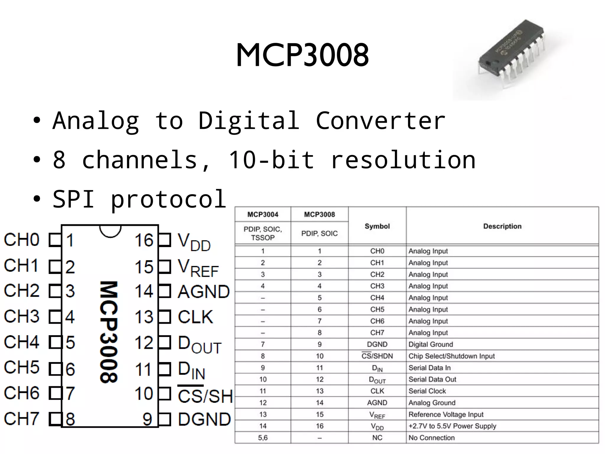
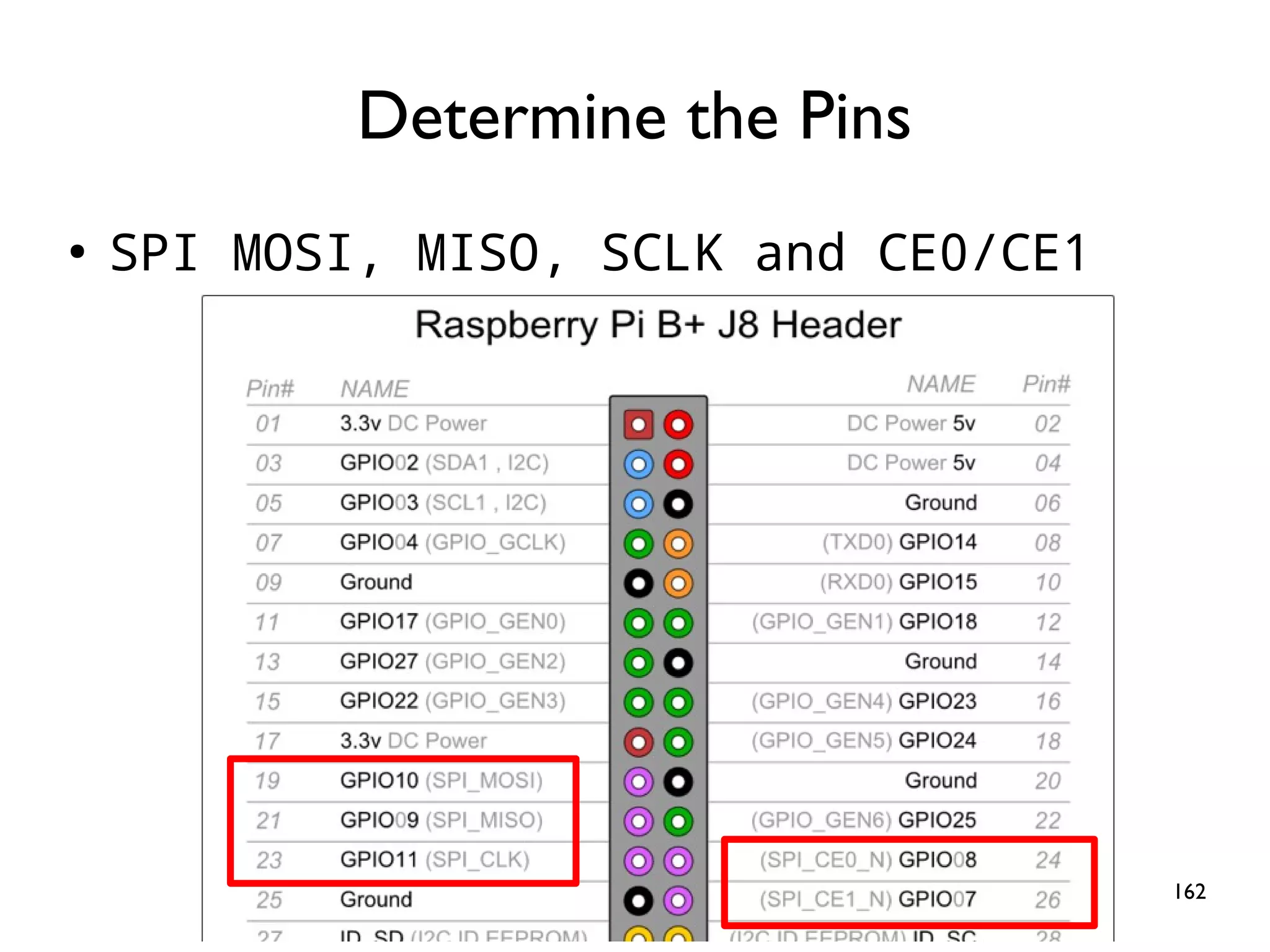
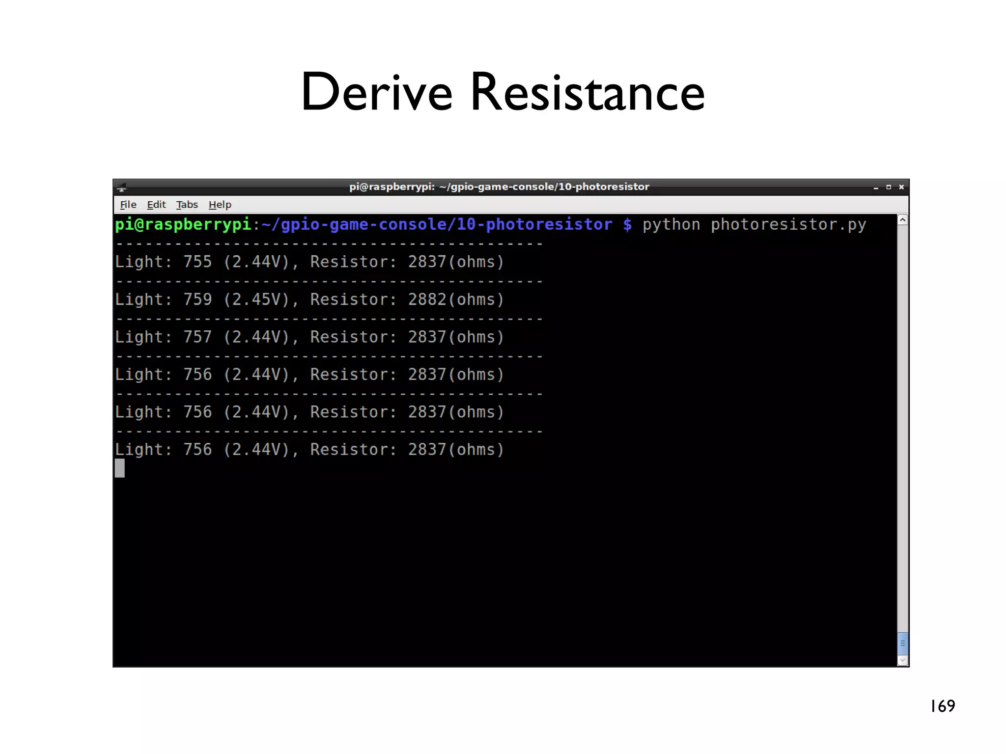
![163 spi = spidev.SpiDev() spi.open(0,0) # (0,0) indicates CE0 and /dev/spidev0.0 spi.max_speed_hz = 1800000 # 10kHz to 3.6 MHz ● ● def ReadChannel(channel): adc = spi.xfer2([1,(8+channel)<<4,0]) data = ((adc[1]&3) << 8) + adc[2] return data def ConvertVolts(data,places): volts = (data * 3.3) / float(1023) volts = round(volts,places) return volts light_channel = 0 delay = 1 while True: light_level = ReadChannel(light_channel) light_volts = ConvertVolts(light_level, 2) print("Light:{} ({}V)".format(light_level,light_volts)) time.sleep(delay)](https://image.slidesharecdn.com/raspberry-pi-gpio-tutorial-en-190902223232/75/Raspberry-Pi-GPIO-Tutorial-Make-Your-Own-Game-Console-163-2048.jpg)
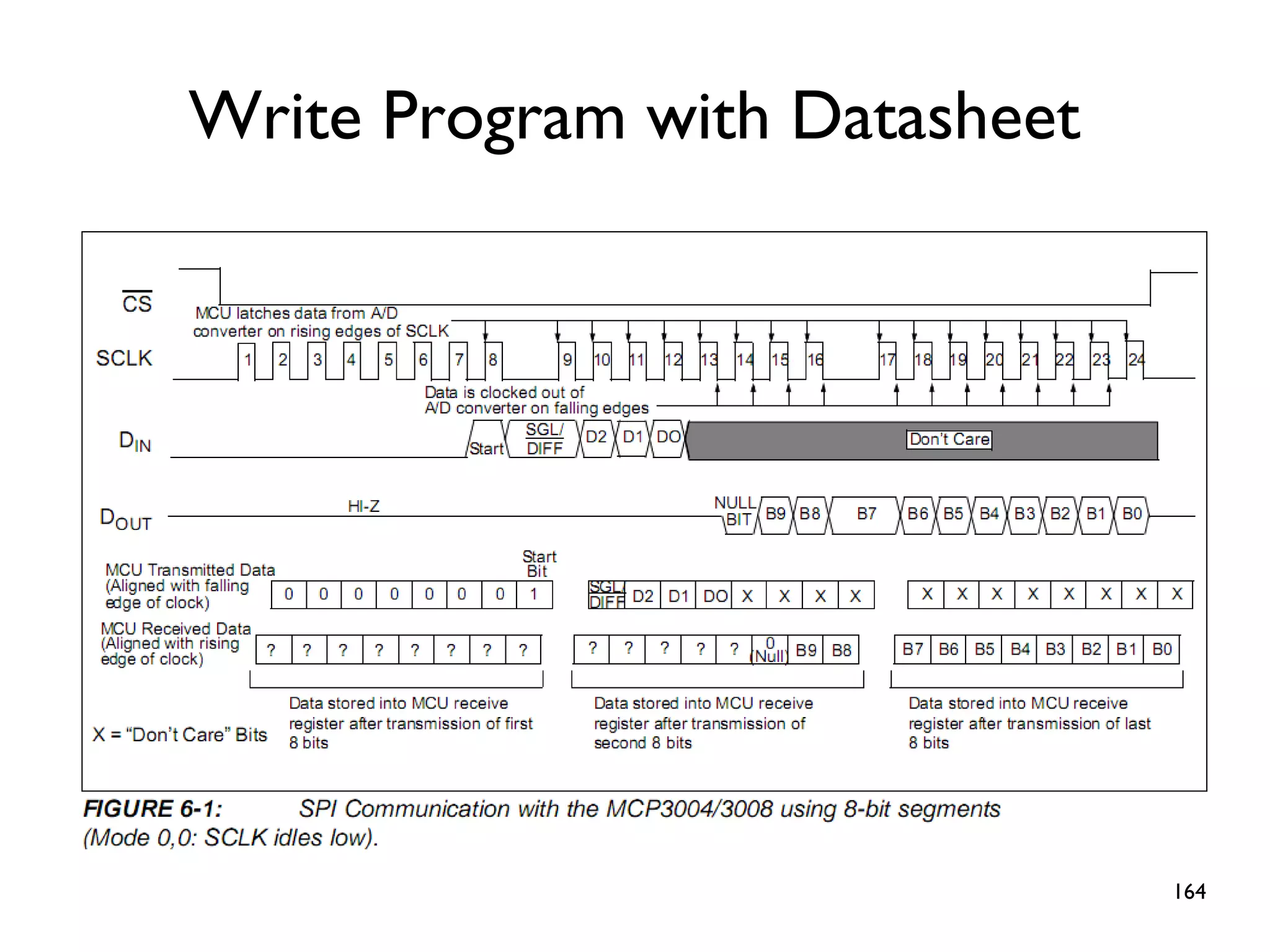
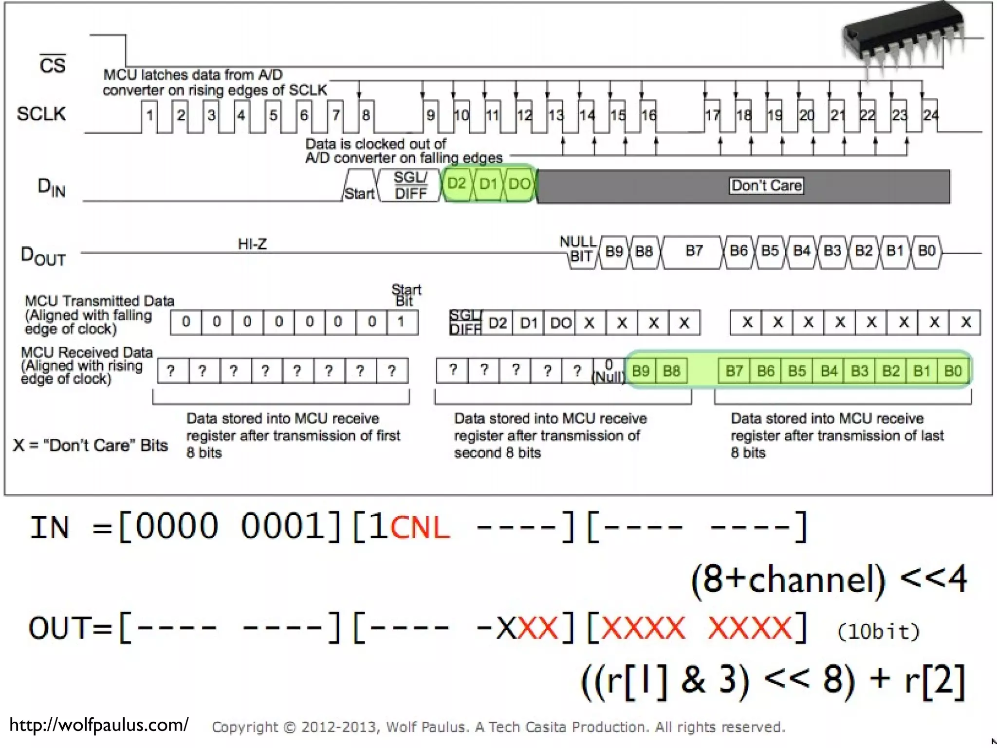
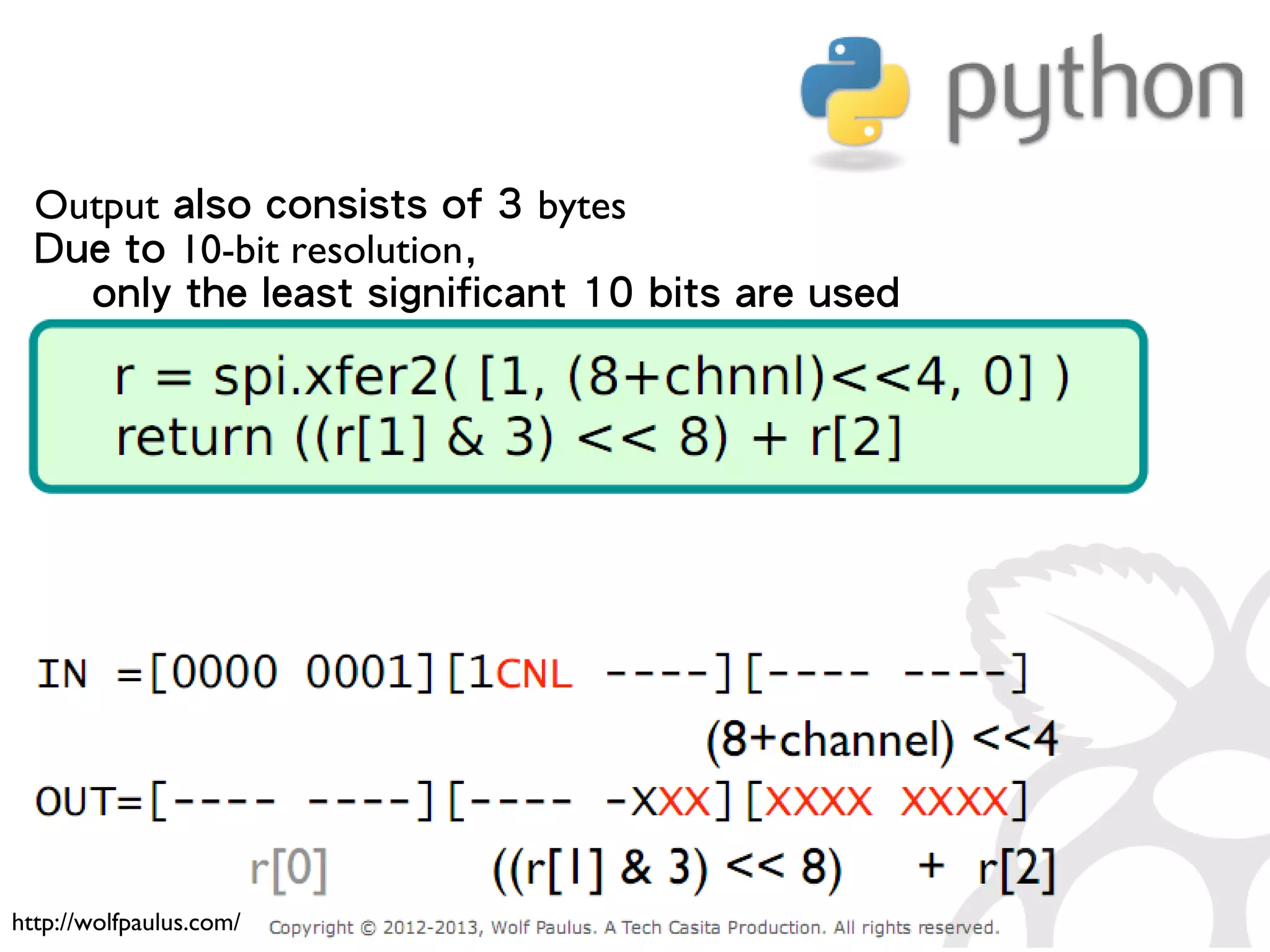
![165 ● Input consists of 3 bytes ● # byte 1: the start bit (always 0x01) ● # byte 2: configure bits ● # byte 3: don't care ● spi.xfer2([1,(8+channel)<<4,0]) ● Ch0 = 1000 0000 ● Ch1 = 1001 0000 Understand spi.xfer2() 0x01 don't careCh0/Ch1](https://image.slidesharecdn.com/raspberry-pi-gpio-tutorial-en-190902223232/75/Raspberry-Pi-GPIO-Tutorial-Make-Your-Own-Game-Console-165-2048.jpg)


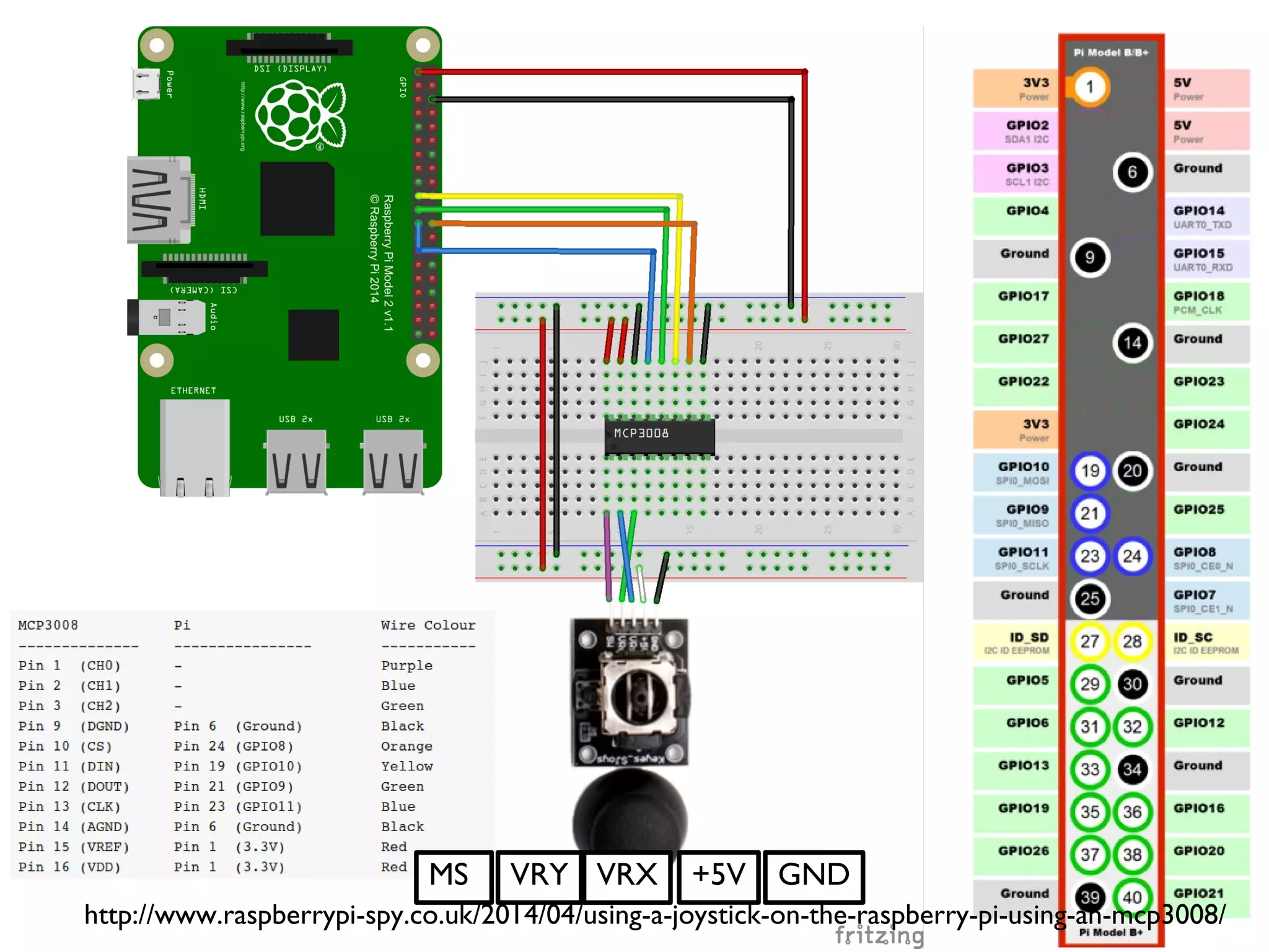
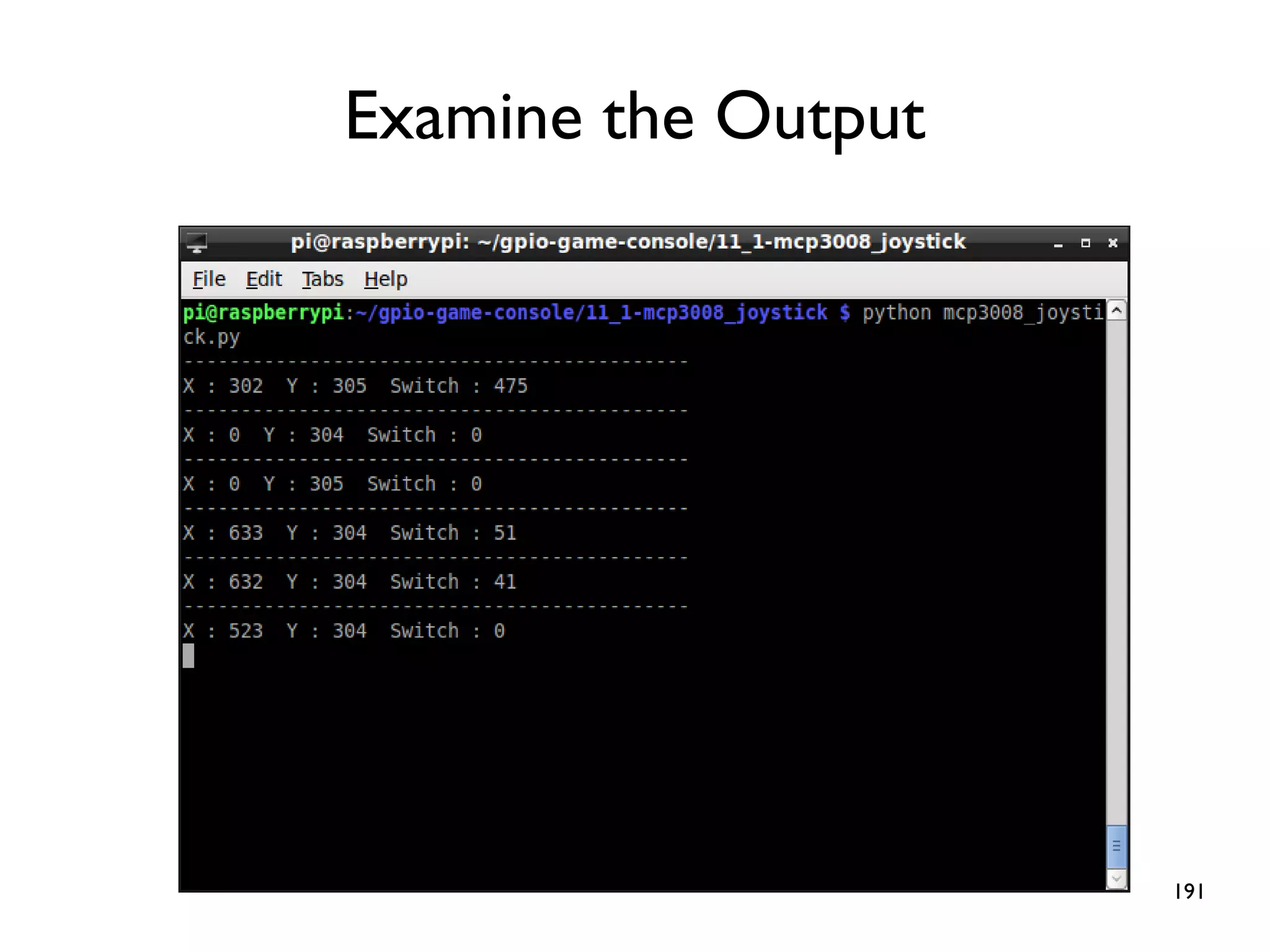
![189 spi = spidev.SpiDev() ● spi.open(0,0) ● spi.max_speed_hz = 1800000 ● ● def ReadChannel(channel): ● adc = spi.xfer2([1,(8+channel)<<4,0]) ● data = ((adc[1]&3) << 8) + adc[2] ● return data ● ● vrx_channel = 1 ● vry_channel = 2 ● ● while True: ● vrx_pos = ReadChannel(vrx_channel) ● vry_pos = ReadChannel(vry_channel) ● ● print("X : {} Y : {} ".format(vrx_pos,vry_pos)) ● ● time.sleep(0.5)](https://image.slidesharecdn.com/raspberry-pi-gpio-tutorial-en-190902223232/75/Raspberry-Pi-GPIO-Tutorial-Make-Your-Own-Game-Console-189-2048.jpg)


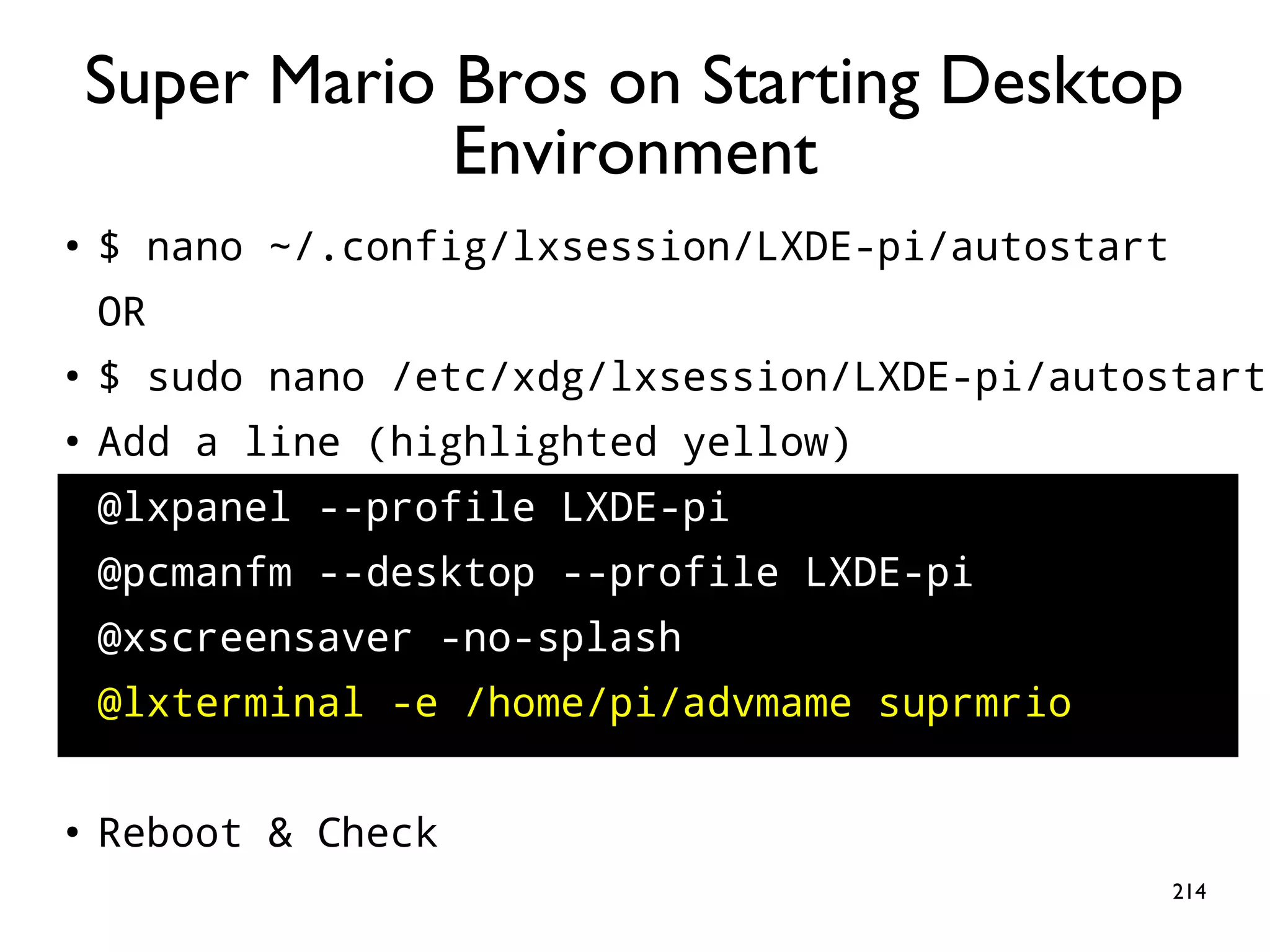
![213 ● Add a line (highlighted yellow) ● $ sudo nano /etc/rc.local sudo python /home/pi/gpio-game-console/13- gaming_console/gaming_console.py & # Print the IP address _IP=$(hostname -I) || true if [ "$_IP" ]; then printf "My IP address is %sn" "$_IP" fi exit 0 Key-press Mapper at Boot Note: a single line](https://image.slidesharecdn.com/raspberry-pi-gpio-tutorial-en-190902223232/75/Raspberry-Pi-GPIO-Tutorial-Make-Your-Own-Game-Console-213-2048.jpg)


![224 ● Set display resolution to 256x240x60 ● TAB-key to activate the menu, choose [Video Mode], ESC-key to leave My AdvanceMAME is Slooow](https://image.slidesharecdn.com/raspberry-pi-gpio-tutorial-en-190902223232/75/Raspberry-Pi-GPIO-Tutorial-Make-Your-Own-Game-Console-224-2048.jpg)
![225 ● Set display resolution to 256x240x60 ● TAB-key to activate the menu, choose [Video Mode], ESC-key to leave My AdvanceMAME is Slooow](https://image.slidesharecdn.com/raspberry-pi-gpio-tutorial-en-190902223232/75/Raspberry-Pi-GPIO-Tutorial-Make-Your-Own-Game-Console-225-2048.jpg)
![226 ● Set display resolution to 256x240x60 ● TAB-key to activate the menu, choose [Video Mode], ESC-key to leave My AdvanceMAME is Slooow](https://image.slidesharecdn.com/raspberry-pi-gpio-tutorial-en-190902223232/75/Raspberry-Pi-GPIO-Tutorial-Make-Your-Own-Game-Console-226-2048.jpg)