Downloaded 109 times
![Experiment No: 10 Name: Shyamveer Singh Regno: 11205816 Roll No:B54 Aim: To implement the sequence detector using behavioral modeling. Theory: A sequence detector accepts as input a string of bits: either 0 or 1. Its output goes to 1 when a target sequence has been detected. There are two basic types: overlap and nonoverlap. In an sequence detector that allows overlap, the final bits of one sequence can be the start of another sequence. Our example will be a 11011 sequence detector. It raises an output of 1 when the last 5 binary bits received are 11011. At this point, a detector with overlap will allow the last two 1 bits to serve at the first of a next sequence. By example we show the difference between the two detectors. Suppose an input string 11011011011. Sequence detector state transition diagram: For 1011 module seqdetector(clk,reset,inp,state,z); input clk,reset,inp; output reg [2:0]state; output reg z; parameter s0=2'b00, s1=2'b01, s2=2'b10, s3=2'b11; always@(clk or reset)](https://image.slidesharecdn.com/1120581613825111205816-150424063122-conversion-gate02/75/Sequence-detector-Verilog-Code-1-2048.jpg)
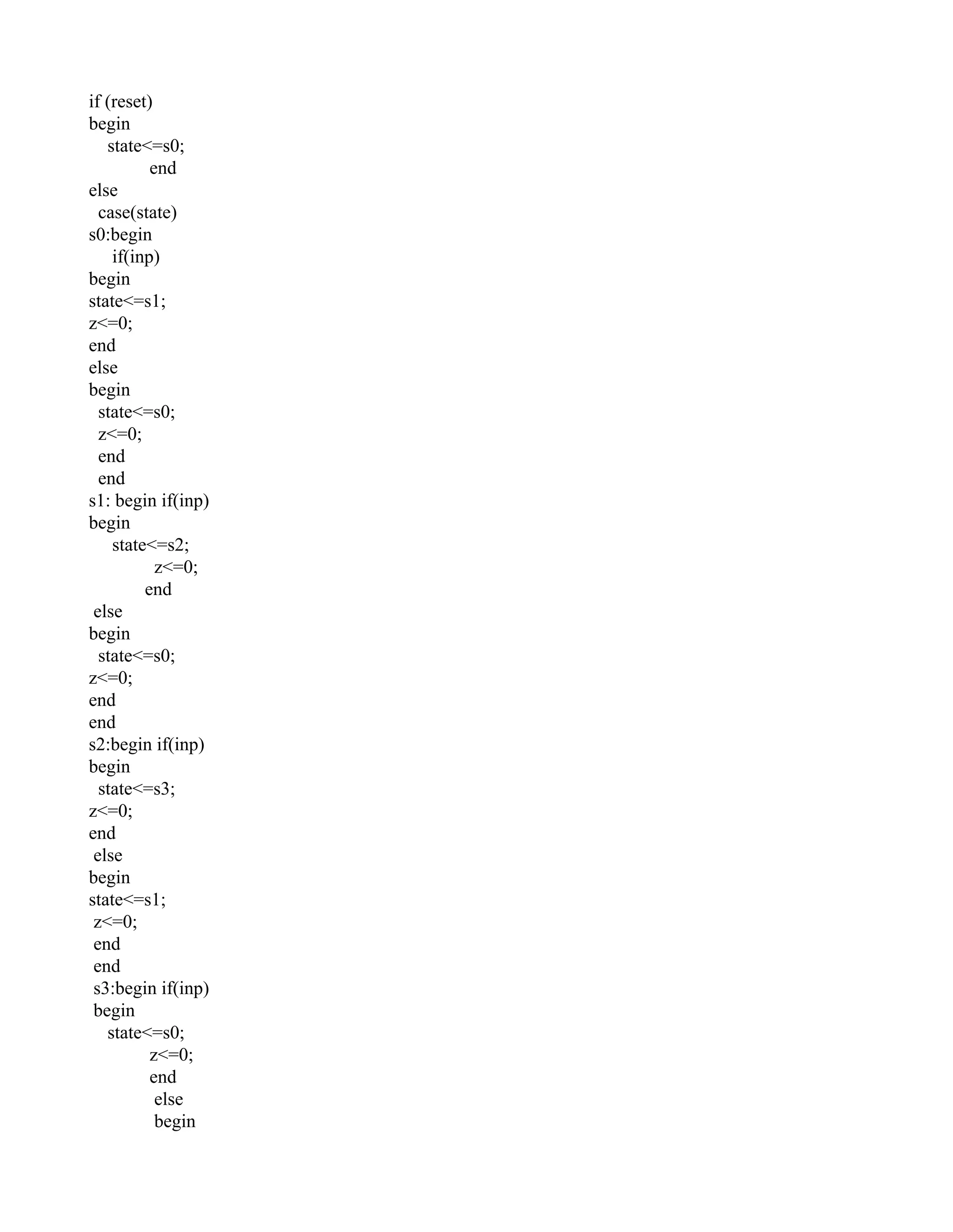

This document describes an experiment to implement a sequence detector using behavioral modeling. The sequence detector will output a 1 when it detects the input sequence of 11011. It includes the state transition diagram for detecting the 1011 sequence and the Verilog code for the sequence detector module. The code defines the different states like s0, s1, etc. and uses case statements to transition between the states based on the current input and update the output. The learning outcome is understanding how to detect a sequence step-by-step and learning Xilinx software commands.
This slide presents the aim of implementing a sequence detector using behavioral modeling and explains the working of overlap and non-overlap sequence detectors.
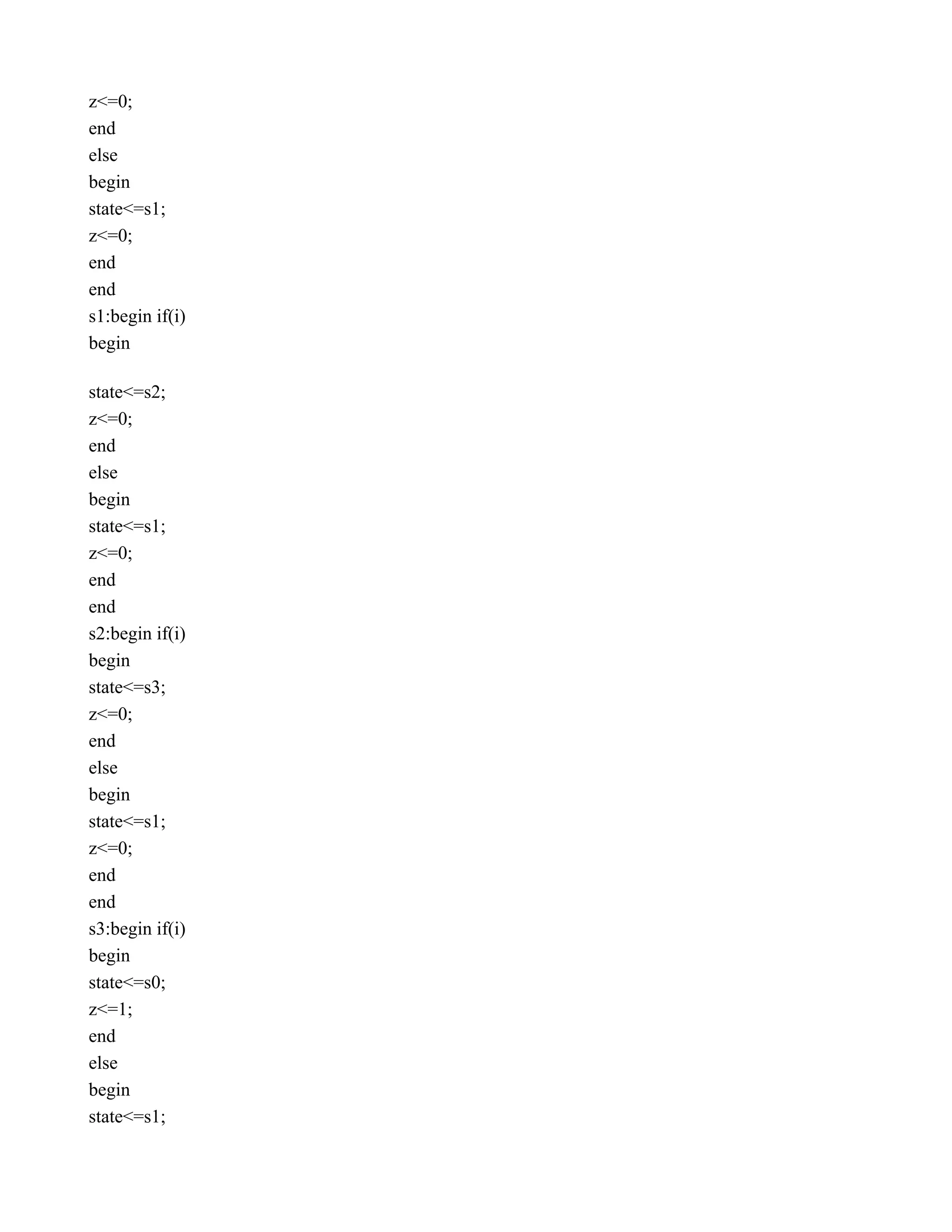
The slide outlines the state transition logic of the sequence detector, detailing the functionality of states s0 to s3 based on input.
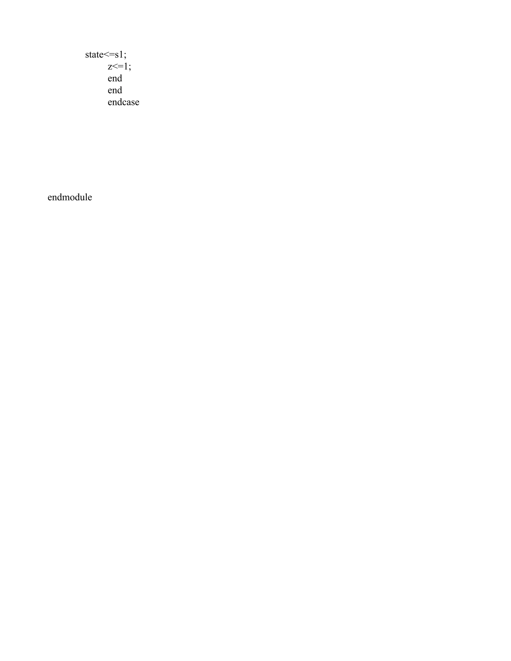
This slide continues with the logical structure of the sequence detector by completing the state transition descriptions.
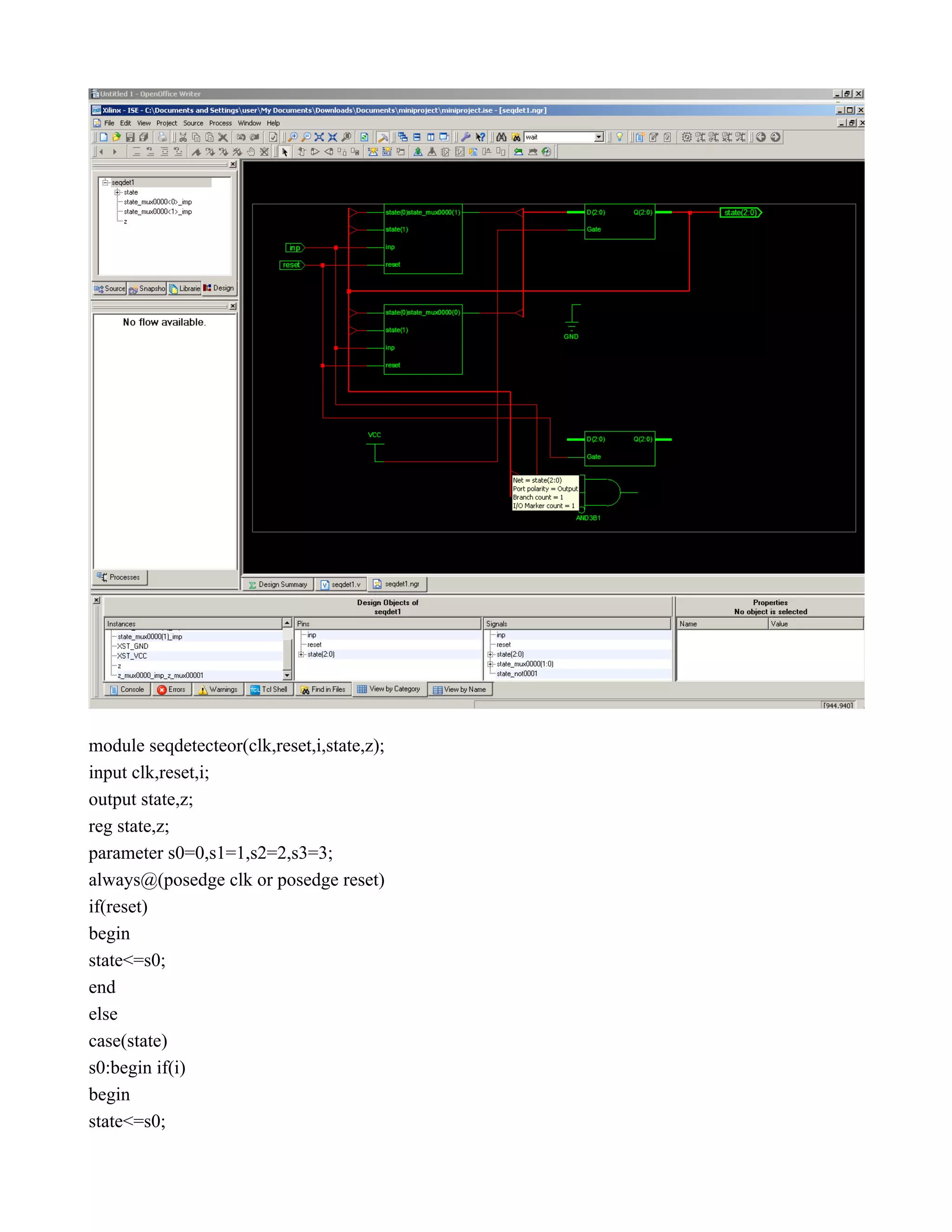
This slide introduces another module for the sequence detector, providing input parameters and initial state definitions.
Continues from the previous slide, detailing the code for state control logic of the sequence detector.
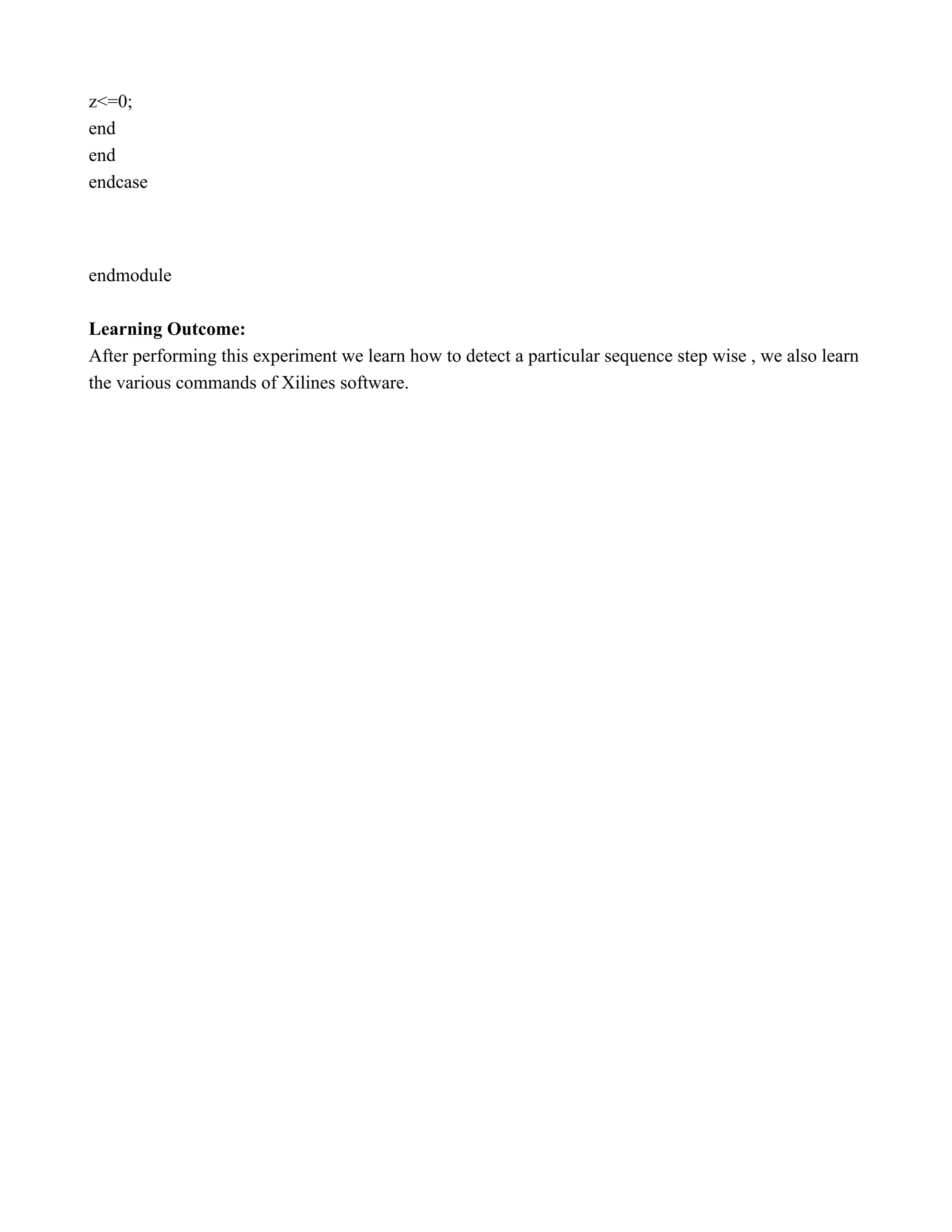
This slide completes the module description and outlines the learning outcome of the experiment focusing on sequence detection and usage of Xilinx software.