Downloaded 224 times
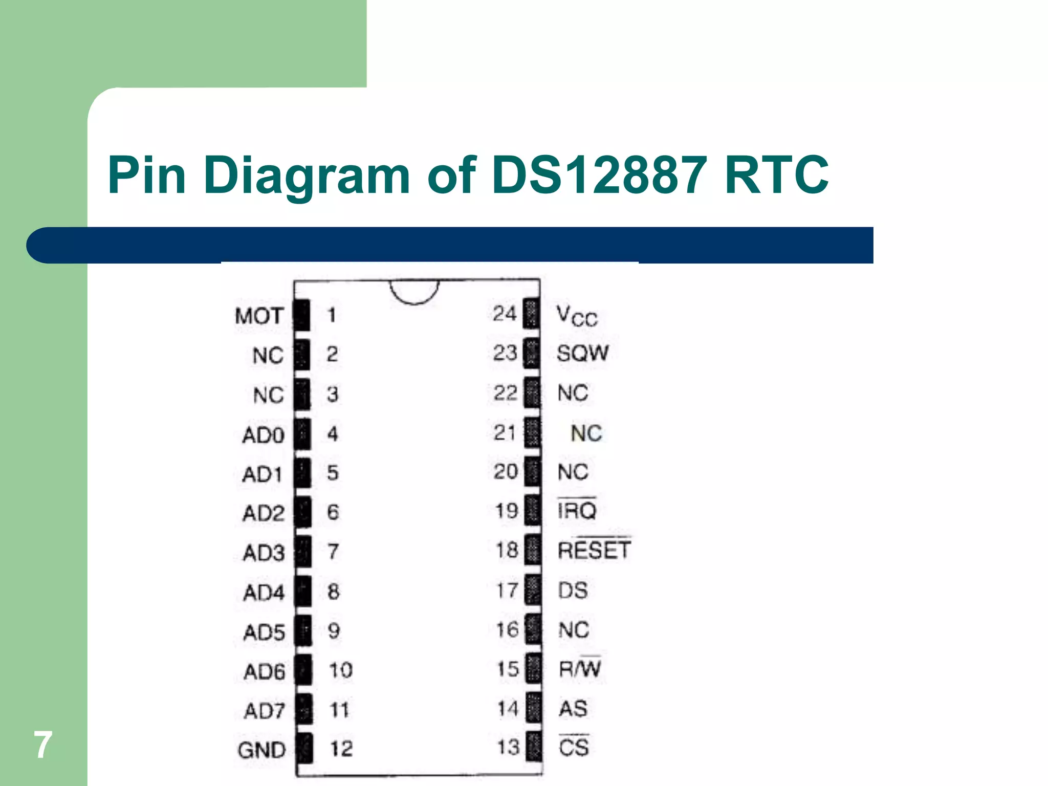
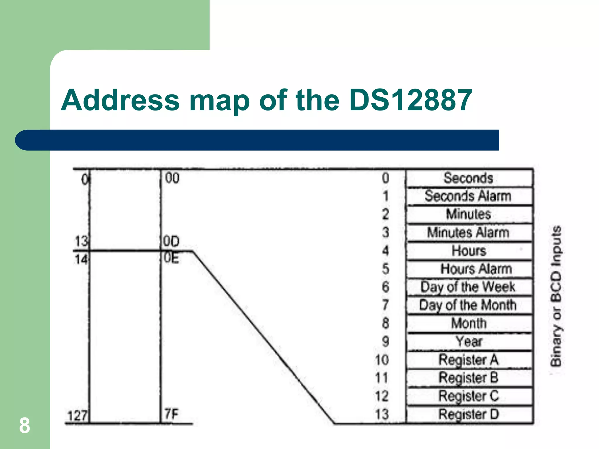
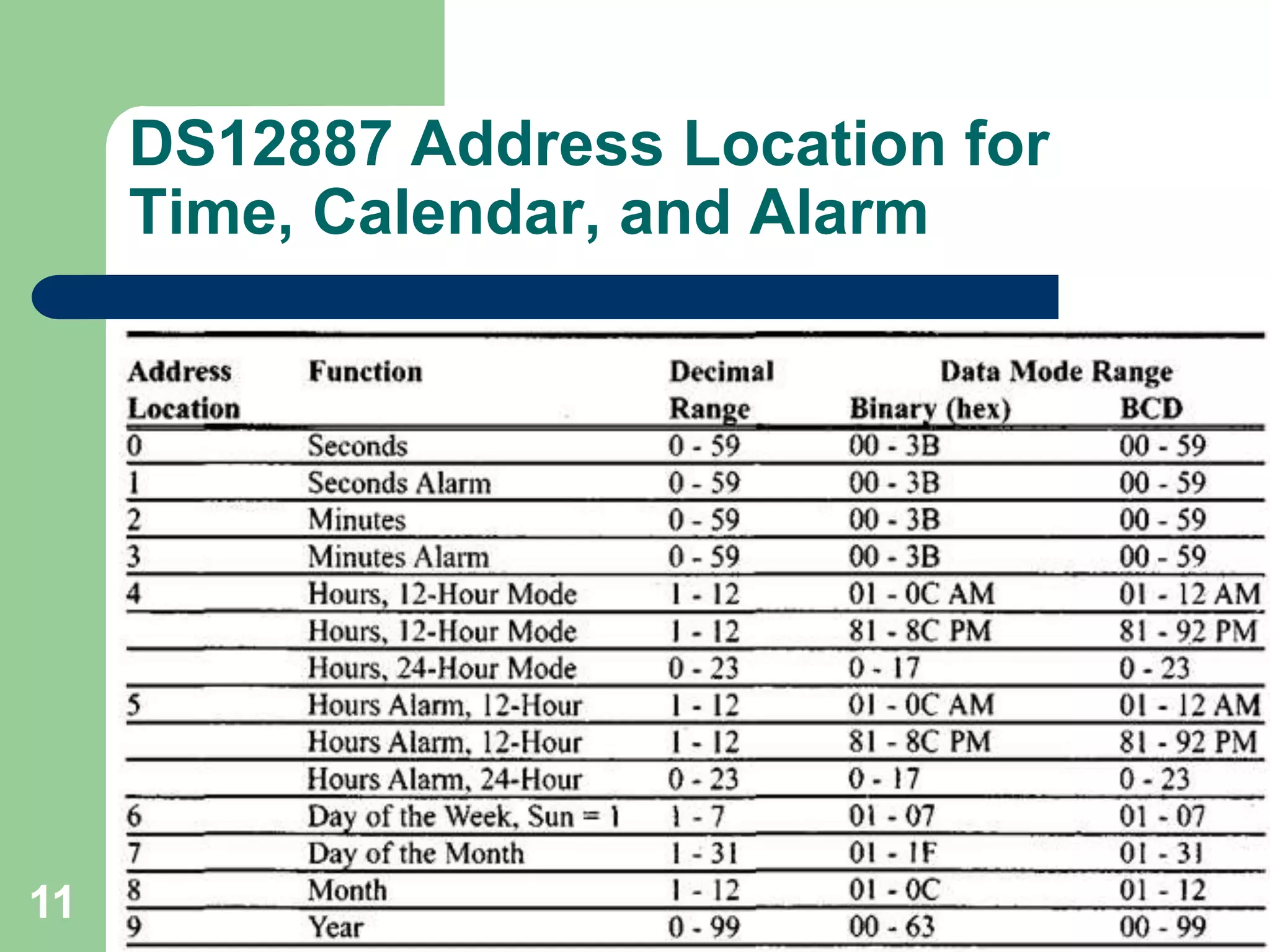
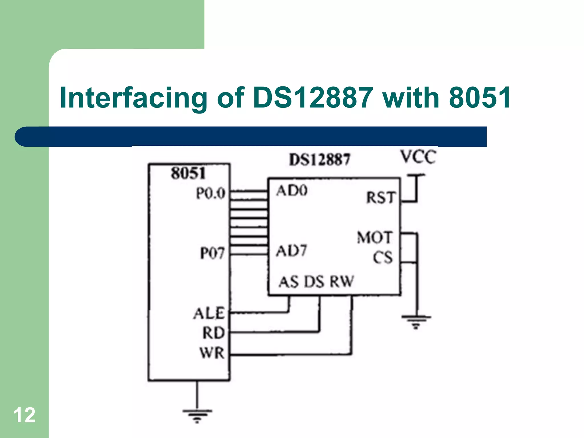


The document provides an overview of the DS12887 real-time clock (RTC) chip used in embedded systems, detailing its features such as timekeeping, alarms, and interfacing with microcontrollers. It explains the chip's internal architecture, memory allocation, and capabilities for handling time and date information, including leap year calculations. Additionally, it covers programming aspects for alarms and interrupt requests associated with the DS12887, facilitating efficient time management in various applications.