Downloaded 32 times


![LED Blinking Using RaspberryPI Blinking is done by connecting an LED to one [Here in our Program PIN 25] of GPIO pins of PI and turning it ON and OFF.](https://image.slidesharecdn.com/ledblinking-181102120413/75/LED-Blinking-Using-Raspberry-Pi-3-2048.jpg)


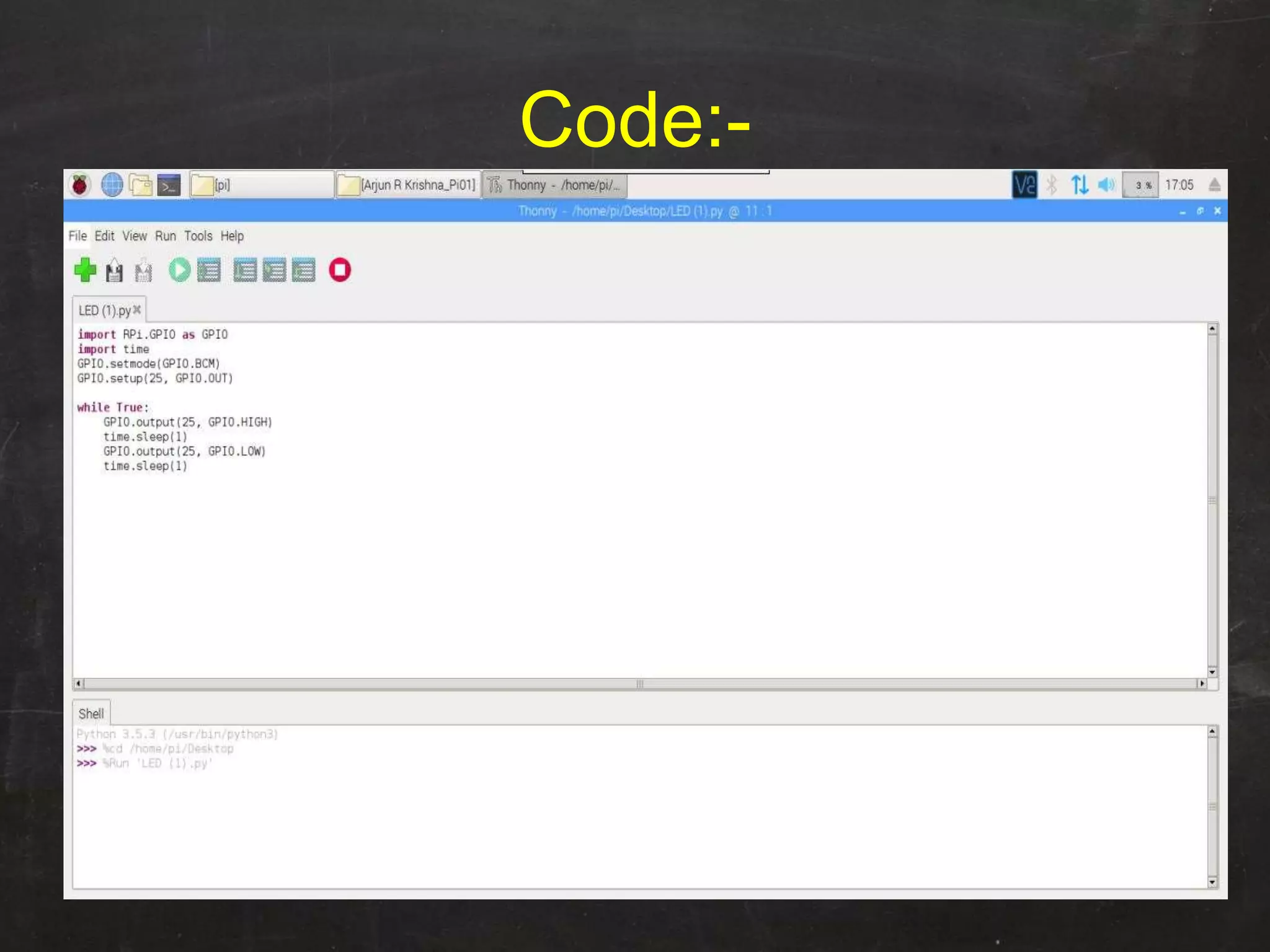


Raspberry Pi is used to blink an LED by connecting it to GPIO pin 25. A resistor is added in series to limit the current. Python code is written to import GPIO and time libraries, set pin 25 as output, and toggle it between high and low voltages with 1 second delays to turn the LED on and off repeatedly.