The document presents a VHDL design and FPGA implementation of a high data rate turbo decoder based on majority logic codes, aimed at enhancing digital transmission systems. It details the decoding process, architecture, and performance evaluation through simulations, achieving data rates exceeding 500 Mbps with reduced latency. The proposed decoder is validated through co-simulation and demonstrates significant improvements compared to existing architectures.
![International Journal of Electrical and Computer Engineering (IJECE) Vol. 7, No. 4, August 2017, pp. 1824~1832 ISSN: 2088-8708, DOI: 10.11591/ijece.v7i4.pp1824-1832 1824 Journal homepage: http://iaesjournal.com/online/index.php/IJECE VHDL Design and FPGA Implementation of a High Data Rate Turbo Decoder based on Majority Logic Codes A. Boudaoud, M. El Haroussi, E. Abdelmounim ASTI Laboratory, FST Settat, Hassan I University, Settat, Morocco Article Info ABSTRACT Article history: Received Jan 6, 2017 Revised Mar 10, 2017 Accepted Mar 27, 2017 This paper presents the electronic synthesis, VHDL design and implementation on FPGA of turbo decoders for Difference Set Codes (DSC) decoded by the majority logic (ML). The VHDL design is based on the decoding Equations that we have simplified, in order to reduce the complexity and is implemented on parallel process to increase the data rate. A co-simulation using the Dsp-Builder tool on a platform designed on Matlab/Simulink, allows the measurement of the performance in terms of BER (Bit Error Rate) as well as the decoder validation. These decoders can be a good choice for future digital transmission chains. For example, for the Turbo decoder based on the product code DSC (21.11)² with a quantization of 5 bits and for one complete iteration, the results show the possibility of integration of our entire turbo decoder on a single chip, with lower latency at 0.23 microseconds and data rate greater than 500 Mb/s. Keyword: Error correcting codes FPGA implementation Interleaver ML-DSC codes Turbo decoding VHDL language Copyright © 2017 Institute of Advanced Engineering and Science. All rights reserved. Corresponding Author: Abdelghani Boudaoud, ASTI Laboratory, FST Settat, Hassan I University, B.P: 577, Casablanca Road, Km 3, Settat, Morocco. Email: boudaoud586@gmail.com 1. INTRODUCTION The discovery, of Turbo-Codes by C.Berrou [1] in 1993, represents an essential step forward for information transmission systems. Indeed, most terrestrial and satellite transmission standards have also adopted them. Thus NASA uses it in all their space probes since 2003; similarly, the European Space Agency (ESA) lunar probe SMART-1. Turbo-codes are also used as in UMTS, ADSL-2 and in mobile networks 4G- LTE and LTE-Advanced [20]. Initially, the turbo codes were based on convolutional codes concatenated in parallel. R.Pyndiah in 1994 [2] proposed the turbo block codes (TBC), which are an alternative to turbo convolutional codes. These TBC used the decoding weighted inputs and outputs (SISO). The iterative decoding process that we use, follows the model proposed by Pyndiah and built from the “One Step Majority Logic Decodable Codes” (OSMLD) [3] using the soft-out extension threshold decoding classic of Massey [4-9], [14]. The majority decoding uses a linear combination of a reduced set of syndromes represented by the orthogonal Equations. The current digital systems and channel coding especially decoding, require high data rates. Decoding rate depends on the chosen architecture in the electronic design; the complexity of the circuit (ie its surface) is often considered as a critical parameter. In this context of very high throughput, the operating speed must be maximized while minimizing complexity.](https://image.slidesharecdn.com/v171604310mar176janboudaoud2vhdl-201019060320/75/VHDL-Design-and-FPGA-Implementation-of-a-High-Data-Rate-Turbo-Decoder-based-on-Majority-Logic-Codes-1-2048.jpg)
![IJECE ISSN: 2088-8708 VHDL Design and FPGA Implementation of a High Data Rate Turbo Decoder …. (A. Boudaoud) 1825 2. CODING AND DECODING OF PRODUCT CODES 2.1. Product Codes Construction Consider tow systematic block linear codes C1(n1, k1, d1) and C2(n2, k2, d2). Where ni, ki and di are, in order: the code word length, the information symbols number and the Hamming distance (i = 1,2). Product code CP=C2C1 built based on C1 and C2, which has the parameters (n1×n2, k1×k2, d1×d2), is obtained by encoding the k2×k1 information symbols by the C1 code and k2×n1 symbols by C2 code, see Figure 1. In this work, we choose C1=C2 and, DSC(7,3,1), DSC(21,11,2) and DSC(73,45,4) codes. 2.2. Turbo Decoding Principle A turbo decoder consists of SISO decoders (generally two decoders) and interleavers as shown in Figure 2. The channel symbols are received by line machine, by the first decoder which gives soft priori information, and then the channel information and the extrinsic information are interleaved and supplied column by column, to the input of the second decoder. A complete iteration consists of activating each decoder once. Thus, with more iteration, the decoder converges to the right solution, however it requires more time. Figure 1. Product code principle Figure 2. Structure of the turbo decoder 3. THE SISO DECODER 3.1. Threshold Decoding Algorithm The SISO (Soft In-Soft Out) decoder is the base element of the turbo decoding. We used SISO decoder for which the threshold decoding algorithm [3], [4], [13] is given below: For each j = n to 1 a. Calculate the terms Bi and ωi with iє {1,..,M} b. Calculate B0 and w0 c. Calculate the extrinsic information M i iij ByW 1 )21()( d. Calculate jjj Wyy Es yLLR N 0 4 )( e. If (LLR(yj)>0) Hard Decision =1 else Hard Decision =0 Where: a. n: Code length;](https://image.slidesharecdn.com/v171604310mar176janboudaoud2vhdl-201019060320/75/VHDL-Design-and-FPGA-Implementation-of-a-High-Data-Rate-Turbo-Decoder-based-on-Majority-Logic-Codes-2-2048.jpg)
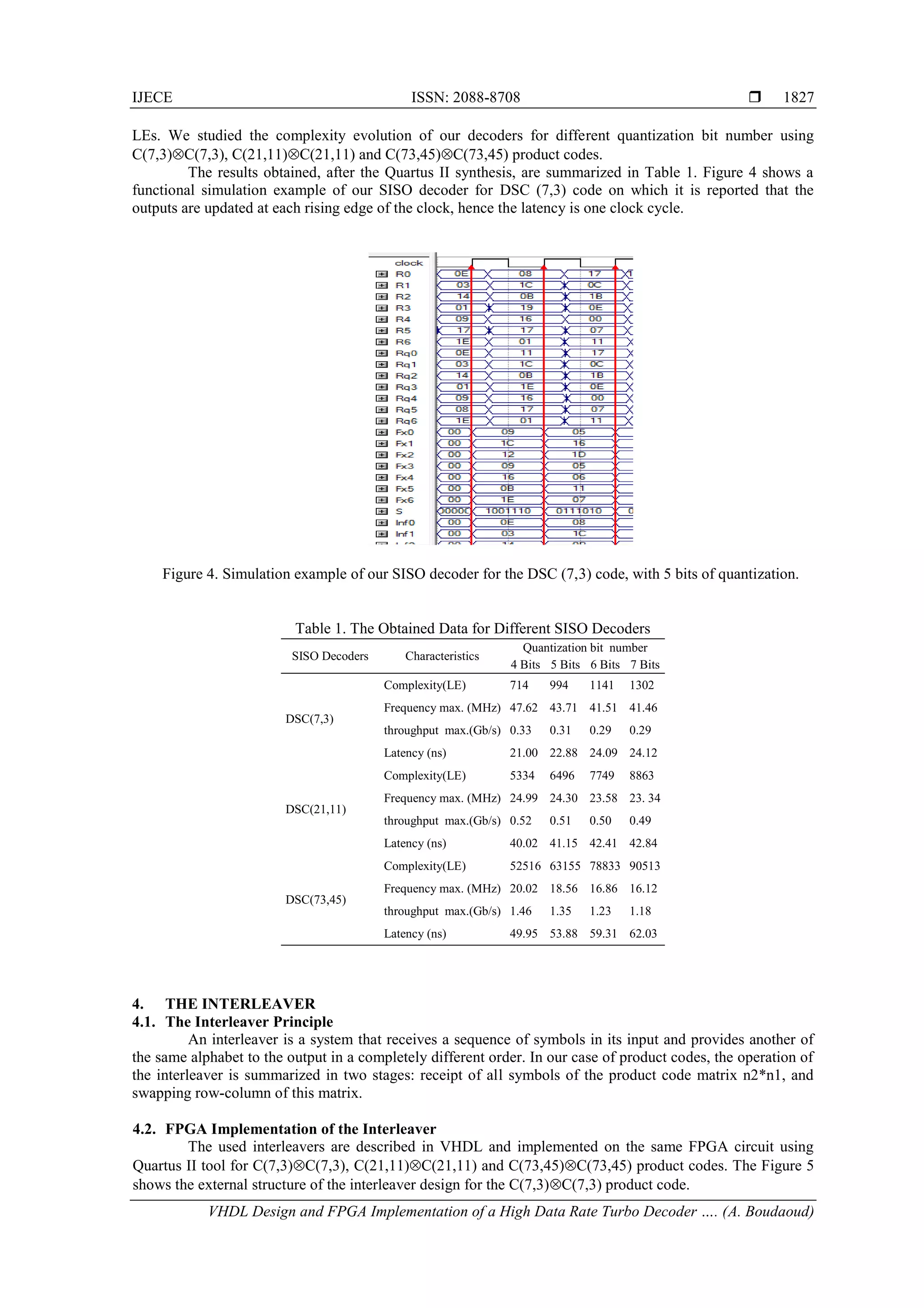
![ ISSN: 2088-8708 IJECE Vol. 7, No. 4, August 2017 : 1824 – 1832 1826 b. M: number of orthogonal Equations; c. Bi: the orthogonal Equation on the ith bit, after remove of ith bit; d. ωi: proportional to the reliability of ith parity Equation, e. W (yj): extrinsic information representing the estimated orthogonal Equations on the symbol yj; f. LLR (yi) the decision function on the symbol yj; And: nik kik ik nik kik ik L L i ,1 ,1 ) 2 tanh(1 ) 2 tanh(1 ln (1) 3.2. Structural Diagram of SISO Decoder We have designed, in VHDL, a SISO decoder, which can be used in an iterative process. This iterative process we use follows the model proposed by Pyndiah [3]; See Figure 3. The soft input and respectively the soft output of the qth step (half-iteration) of the iterative decoding are given by: )()()1( qWqRqR )()(4)( 0 qWqR N E qLLR s Where R represents the lines or columns of the received and quantified word, W(q) the extrinsic information calculated by the previous decoder and α is a coefficient which varies with each iteration. In addition to its threshold output, the decoder has a hard decision output that we used for its validation. Figure 3. SISO Decoder (elementary cell of turbo decoding) 3.3 FPGA Implementation of the SISO Decoder To reduce the complexity of the algorithm, we used, to simplify the expression (1), the Equation (2) below proposed by [12] and applied to the majority logic codes by [13], [11], [21]. The simplified expression of our decoder becomes: (2) The architecture of the proposed SISO decoder was described in VHDL and implemented on FPGA using Quartus II tool from Altera. We used The EPC4CE115F29C7 FPGA type, containing about 115,000 n k ikik ni k LsignLi 1 1 )(*min](https://image.slidesharecdn.com/v171604310mar176janboudaoud2vhdl-201019060320/75/VHDL-Design-and-FPGA-Implementation-of-a-High-Data-Rate-Turbo-Decoder-based-on-Majority-Logic-Codes-3-2048.jpg)
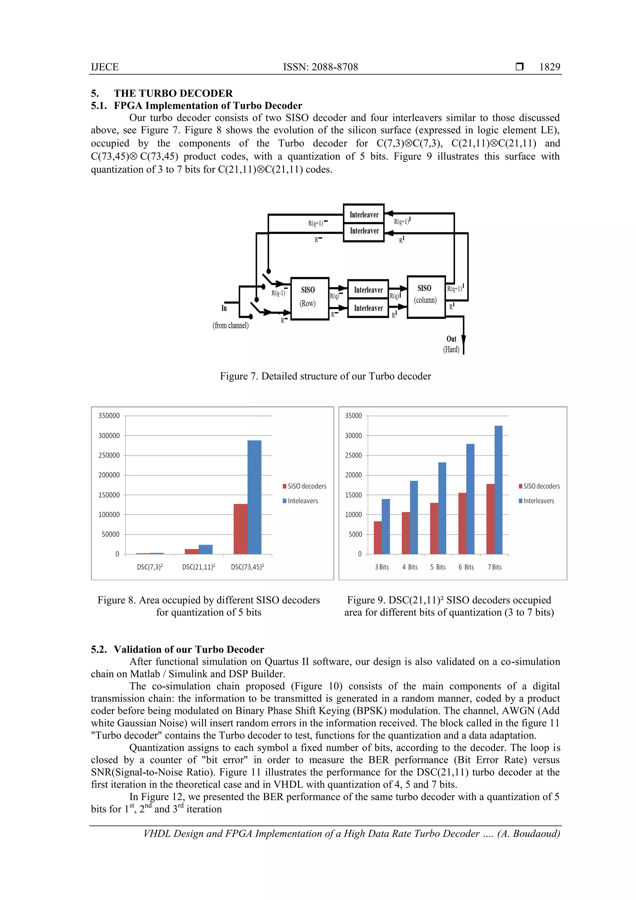
![ ISSN: 2088-8708 IJECE Vol. 7, No. 4, August 2017 : 1824 – 1832 1830 Figure 10: the proposed co-simulation chain for the BER performance measurement of the turbo decoder Figure 12. BER performances of Turbo decoder for 1st , 2nd and 3rd iteration 5.3. Performances of our Turbo Decoder Our turbo decoder designed and implemented on the EPC4CE115F29C7 FPGA circuit presents the performances summarized in Table 3. It is evident from Table 4, that the proposed design has a good performance compared to other recent architectures; and especially the latency that is nine times lower than the least one in the other designs. Table 3. Summary of DSC (21, 11) Turbo Decoder Performances With a Quantization of 5 Bits. IterationPath* Throughput max. (Mb/s) Latency min. (µs) Complexity (LE) Occupation (%) BER at SNR=3dB 1 2S+I 510 0.224 24 590 21.38% 4.72 10-2 2 4S+3I 255 0.590 36 188 31.46% 9.91 10-4 3 6S+5I 170 0.956 36 188 31.46% 5.62 10-5 (*) Information path: S for SISO decoder and I for Interleaver Table 4. Comparaison With Others Turbo Decoder Design This work [18] 2010 [15] 2005 [16] 2003 [17] 20132nd iter. 3rd iter. Number of Iterations 2 3 5 6 4 NA Throughput (Mb/s) 255 170 930 758 75.6 346 Latency(µs) 0.59 0.956 5.5 10.5 5.35 NA Frame length 441 441 5120 5120 432 NA BER at SNR=3dB 9.9 10-4 5.6 10-5 4 10-6 NA 4 10-7 2 10-3 Modulation BPSK BPSK BPSK NA NA BPSK Channel type AWGN AWGN AWGN NA NA AWGN Code rate 0.274 0.274 NA NA 0.33 0.33](https://image.slidesharecdn.com/v171604310mar176janboudaoud2vhdl-201019060320/75/VHDL-Design-and-FPGA-Implementation-of-a-High-Data-Rate-Turbo-Decoder-based-on-Majority-Logic-Codes-7-2048.jpg)
![IJECE ISSN: 2088-8708 VHDL Design and FPGA Implementation of a High Data Rate Turbo Decoder …. (A. Boudaoud) 1831 6. CONCLUSION The approach of the VHDL design using a parallel mode and the FPGA implementation of the proposed turbo decoder has allowed us a high data rate, low complexity and very low latency. This will justify its use in future communication channels. Use of a FPGA circuit with better “Speedgrad” could further increase data rate and reduce latency. In addition, a review of the interleaver architecture is necessary to reduce more its complexity. REFERENCES [1] C Berrou, A. Glavieux, P. Thitimajshima, “Near Shannon Limit Error Correcting Coding and Decoding: Turbo Codes”, IEEE International Conference on Communication ICC93, vol. 2/3, May 1993. [2] R. Pyndiah, A. Glavieux, A. Picart, S. Jacq, “Near Optimum Decoding of Product Codes”, Globecom'94, San Fransisco,1994. [3] M. Belkasmi, M. Lahmer, F. Ayoub, “Iterative Threshold Decoding of Product Codes Constructed from Majority Logic Decodable Codes”, ICCTA conf, Damascus,Syria, pp. 2376- 2381, April 2006. [4] J. L. Massey, “Threshold Decoding”, M.I.T. Press, Cambridge, Massachusetts, 1963. [5] E. J.. Weldon Jr, “Difference-Set Cyclic Codes”, Bell System Technical Journal, Vol.45, pp. 1045_1055, sep 1966. [6] R. L. Graham, F. J. MacWilliams, “On the Number of Information Symbols in Difference-Set Cyclic Codes”, Bell System Technical Journal, vol. 45, pp. 1057-1070, Sep 1966. [7] J. Singer, “A Theorem in Finite Projective Geometry and Some Applications to Numbers Theory”, AMS Trans., vol. 43, pp. 377-385, 1938. [8] F. J. MacWilliams, “A Table of Primitive Binary Idempotents of odd Length n, 7 ≤n ≤511”, IEEE Trans. Inform. Theory, vol. IT-25, pp. 118–123, Jan. 1979. [9] F. J. MacWilliams, J. Seery, “The weight Distributions of some minimal Cyclic Codes,” IEEE Trans. Inform. Theory, vol. IT-27, pp. 796–806, Nov. 1981 [10] C. Clarck, B. Cain, “Error-Correction Coding for Digital Communications,” Plenum Press, 1983. [11] M. Elharoussi, M. Belkasmi, “VHDL Design and FPGA Implementation of a Fully Parallel Architecture for Iterative Decoder of Majority Logic Codes for High Data Rate Applications”, Journal of Wireless Networking and Communications (JWNC), 2(4), pp. 35-42, 2012 [12] J. Hagenauer, E. Offer, L. Papke, “Iterative Decoding of Binary Block and Convolutional Codes”, IEEE Trans. Inform. Theory, Mars 1996, Vol. 42, pp. 429-446. [13] A.Boudaoud, E.Abdelmounim, A. Barazzouk, J. Zbitou, M.Belkasmi, “FPGA Implementation of HIHO and SIHO Decoders for DSC Codes”, IEEE explorer, pp. 1461 – 1464, April 2014 [14] L. D. Rudolph, “Geometric Configuration and Majority Logic Decodable Codes”, PhD thesis, University of Oklahoma, Norman, 1964. [15] G. Prescher, T. Gemmeke, T.G. Noll, “A parametrizable Lowpower High-throughput Turbo-decoder,” in IEEE Int. Conf. Acoustics, Speech, and Signal Processing (ICASSP), volume 5, pages 25-28, Mar. 2005. [16] B. Bougard, A. Giulietti, V. Derudder, J. Willem, S. Dupont, F. Catthoor, L. Hollevoet, L. V. der Perre, H. D. Man, R. Lauwereins, “A scalable 8.7 nj/bit 75.6 Mb/s parallel concatenated convolutional (turbo-)codec,” in IEEE Int. Solid-State Circuit Conf., pp. 152–484, Feb. 2003. [17] Rahul Shrestha, Roy P Paily, “Design and Implementation of a High Speed MAP Decoder Architecture for Turbo Decoding”, 26th IEEE International Conference on VLSI Design and the 12th IEEE International Conference on Embedded Systems, pp. 86-91, 2013. [18] S. M. Karim, I. Chakrabarti, “An Improved Low-power High-throughput log-MAP Turbo Decoder", IEEE Trans. Consum. Electron., vol. 56, no. 2, pp. 450-457, 2010 [19] A. Z. Jidin, T. Sutikno, “FPGA Implementation of Low-Area Square Root Calculator”, TELKOMNIKA Telecommunication, Computing, Electronics and Control, 2015; 13(4): 1145-1152. [20] Yi Bo-nian, “Turbo Code Design and Implementation of High-Speed Parallel Decoder”, TELKOMNIKA, Vol. 11, no. 4, April 2013, pp. 2116~2123 [21] M. Elharoussi, M. Belkasmi, “Design and FPGA Implementation of a Fully Parallel Architecture for Turbo decoding of majority logic codes For High data rate Applications”, International Journal of Computing and Information Technology (IJCIT), Vol. 3, N_2, pp. 81-95, 2011](https://image.slidesharecdn.com/v171604310mar176janboudaoud2vhdl-201019060320/75/VHDL-Design-and-FPGA-Implementation-of-a-High-Data-Rate-Turbo-Decoder-based-on-Majority-Logic-Codes-8-2048.jpg)