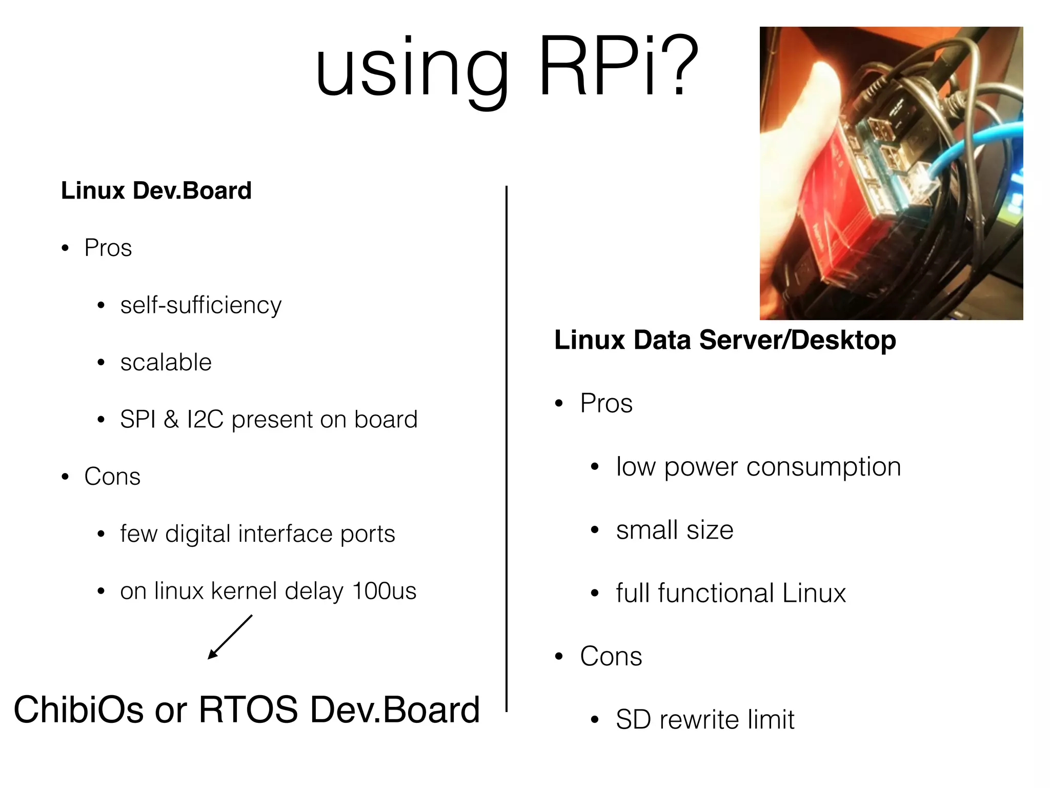
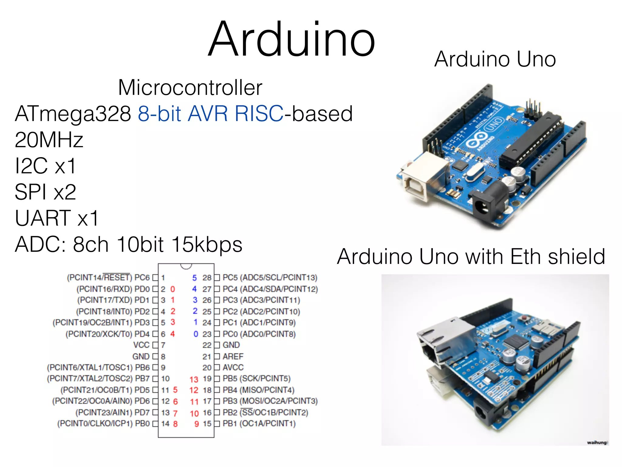
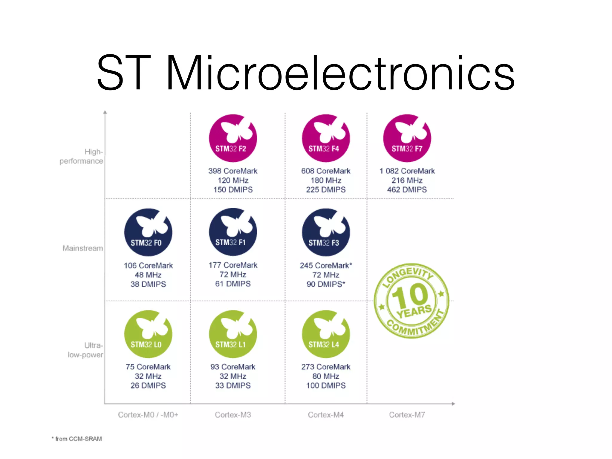
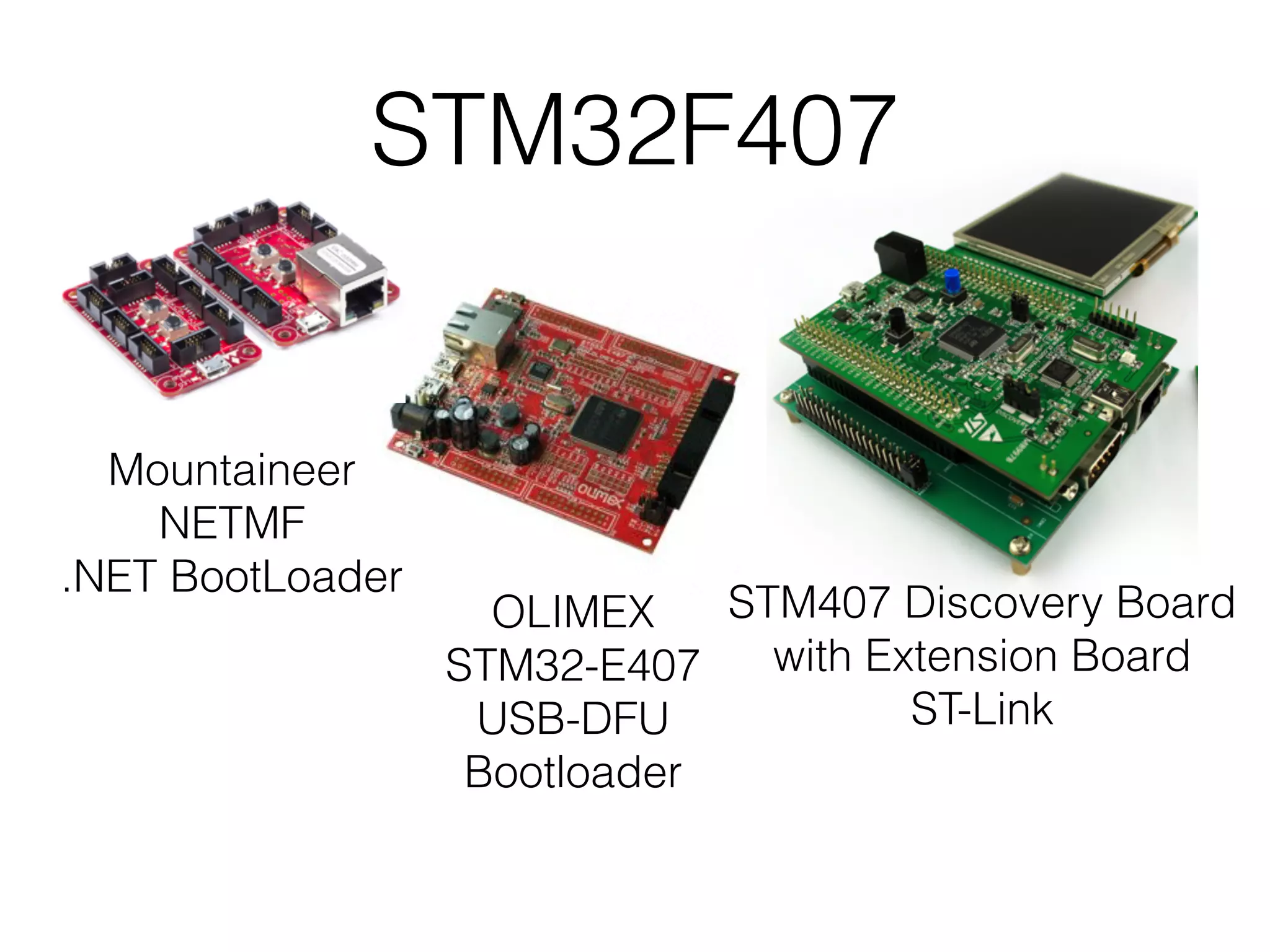
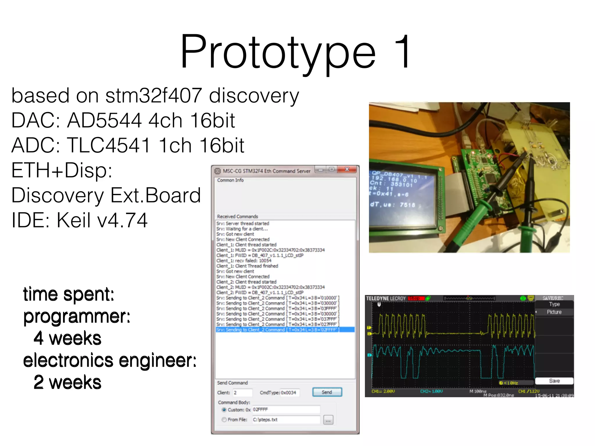
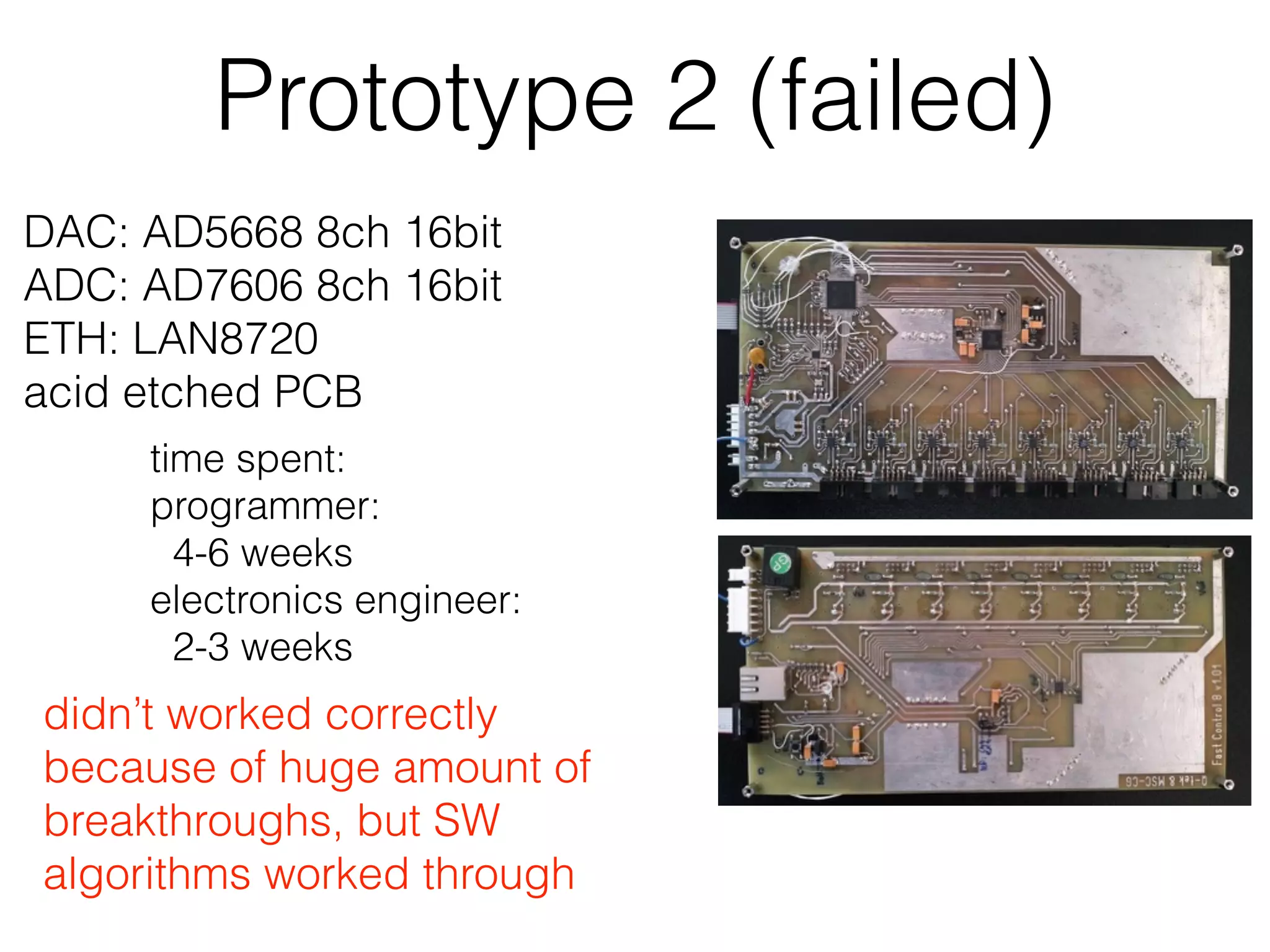
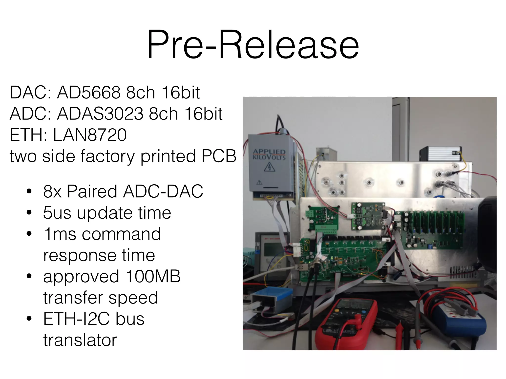
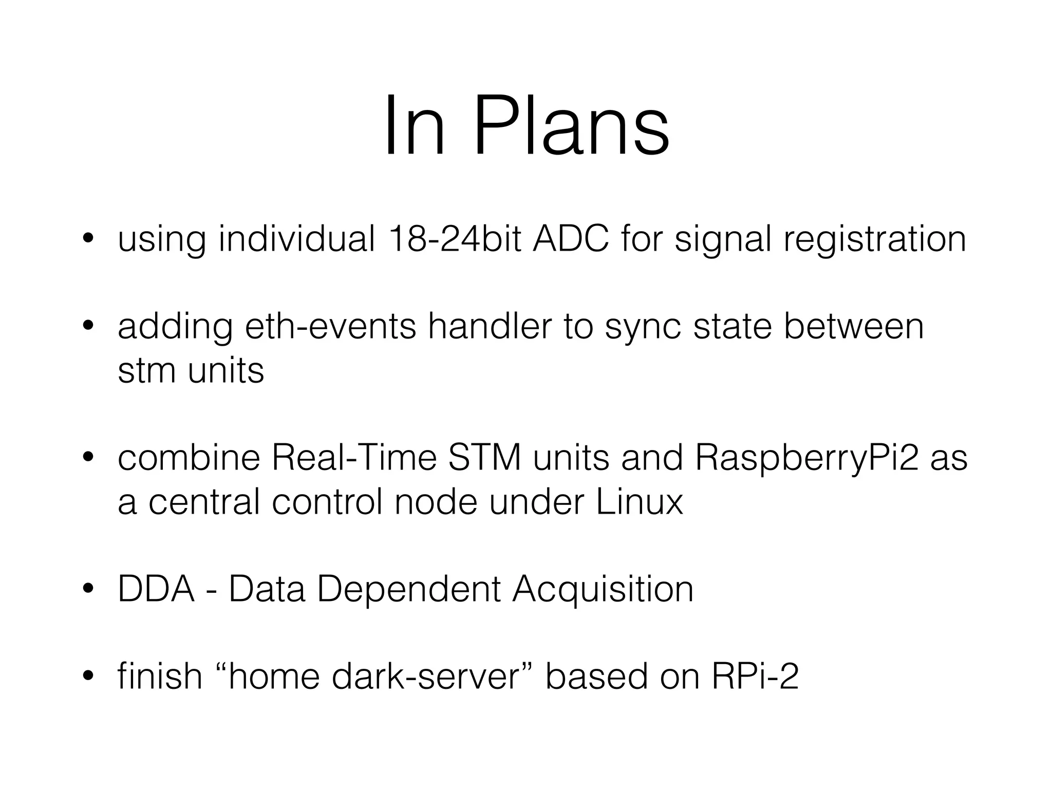
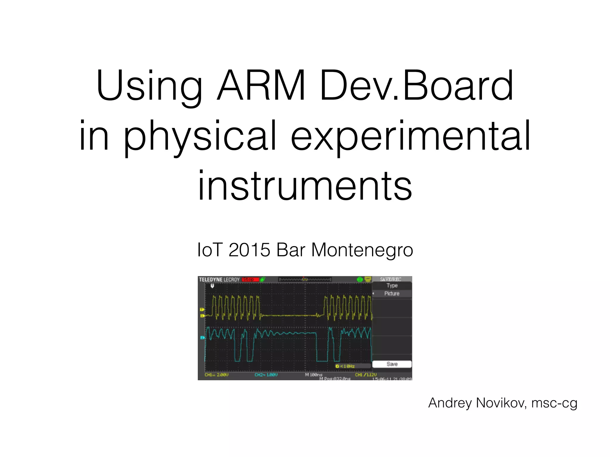
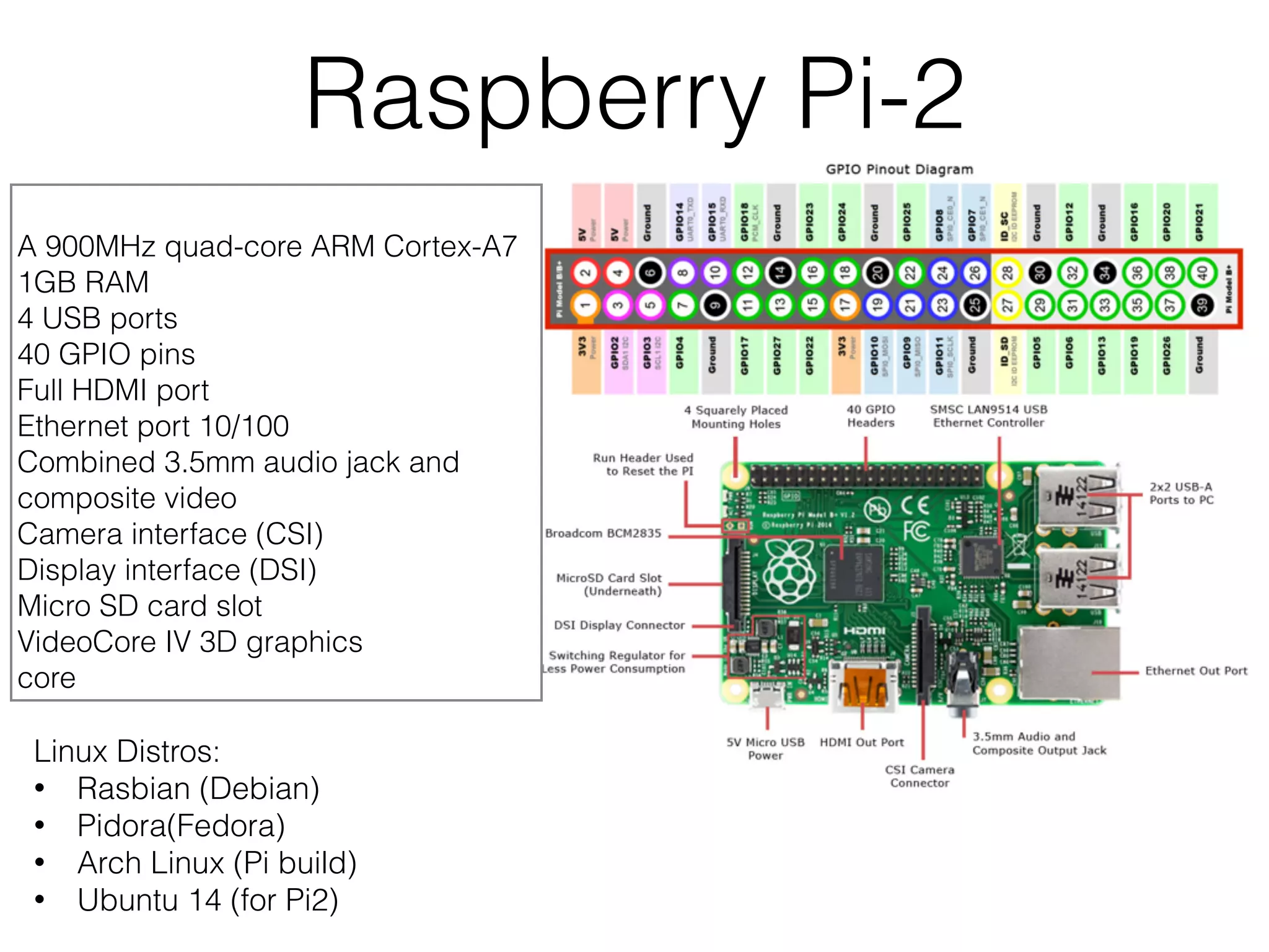
Using ARM Dev.Board in physical experimental instruments IoT 2015 Bar Montenegro Andrey Novikov, msc-cg
mass spectrometry Sector MS (1936) Time of Flight MS (1948) Quadrupole (1970) deflection
Sector Mass-Spectrometer
ToF MS
Quadrupole
What we had before • static voltages on lenses • FTDI USB-I2C bus • 2-20ms per command • 1-2% of lost commands • update frequency 5-10Hz
Requested Specification • Change Voltage 2-4 channels every 10-20us (precision 16bit 0.1mV/10V) • Measure 1 Voltage (16-24bit) channel on each step. • measured data samples without time gaps for 1s (100000 samples on that frequency) • transfer all acquired data less then 10ms to the PC. • be ready for new cycle. • should be easily scalable
Interfaces microcontroller layer digital Interfaces • GPIO - General Purpose Input Output • SPI - Serial Peripheral Interface • I2C(TWI) - two ware interface PC layer connection data transfer interface • Ethernet 10/100Mb • RS-232 • RS-485
Development Boards • Raspberry Pi • Arduino • ST32F • STM discovery dev board • Mountaineer • OLIMEX
Raspberry Pi-2 A 900MHz quad-core ARM Cortex-A7 1GB RAM 4 USB ports 40 GPIO pins Full HDMI port Ethernet port 10/100 Combined 3.5mm audio jack and composite video Camera interface (CSI) Display interface (DSI) Micro SD card slot VideoCore IV 3D graphics core Linux Distros: • Rasbian (Debian) • Pidora(Fedora) • Arch Linux (Pi build) • Ubuntu 14 (for Pi2)
Raspberry Pi code example #Python import RPi.GPIO as GPIO import time def main(): # Main program block GPIO.setmode(GPIO.BCM) # GPIO.setup(LCD_E, GPIO.OUT) # E GPIO.setup(LCD_RS, GPIO.OUT) # RS GPIO.setup(LCD_D4, GPIO.OUT) # DB4 GPIO.setup(LCD_D5, GPIO.OUT) # DB5 GPIO.setup(LCD_D6, GPIO.OUT) # DB6 GPIO.setup(LCD_D7, GPIO.OUT) # DB7 #etc… def lcd_byte(bits, mode): # Send byte to data pins # bits = data # mode = True for character # False for command GPIO.output(LCD_RS, mode) # RS # High bits GPIO.output(LCD_D4, False) GPIO.output(LCD_D5, False) GPIO.output(LCD_D6, False) GPIO.output(LCD_D7, False) #etc… //C int mcp3008Spi::spiOpen(std::string devspi){ int statusVal = -1; this->spifd = open(devspi.c_str(), O_RDWR); if(this->spifd < 0){ perror("could not open SPI device"); exit(1); } statusVal = ioctl (this->spifd, SPI_IOC_WR_MODE, &(this->mode)); if(statusVal < 0){ perror("Could not set SPIMode (WR)...ioctl fail"); exit(1); } //etc… // Transfer data with SPI: one spi transfer for each byte for (i = 0 ; i < length ; i++){ spi[i].tx_buf = (unsigned long)(data + i); // transmit from "data" spi[i].rx_buf = (unsigned long)(data + i) ; // receive into "data" spi[i].len = sizeof(*(data + i)) ; spi[i].delay_usecs = 0 ; spi[i].speed_hz = this->speed ; spi[i].bits_per_word = this->bitsPerWord ; spi[i].cs_change = 0; } retVal = ioctl (this->spifd, SPI_IOC_MESSAGE(length), &spi) ;
using RPi? Linux Data Server/Desktop • Pros • low power consumption • small size • full functional Linux • Cons • SD rewrite limit Linux Dev.Board • Pros • self-sufficiency • scalable • SPI & I2C present on board • Cons • few digital interface ports • on linux kernel delay 100us ChibiOs or RTOS Dev.Board
Arduino Arduino Uno Microcontroller ATmega328 8-bit AVR RISC-based 20MHz I2C x1
 SPI x2 UART x1
 ADC: 8ch 10bit 15kbps Arduino Uno with Eth shield
ST Microelectronics
STM32F407 STM407 Discovery Board with Extension Board ST-Link Mountaineer NETMF .NET BootLoader OLIMEX STM32-E407 USB-DFU Bootloader
IDE • Keil http://www.keil.com • CooCox CoIDE http://www.coocox.org • .NET MicroFramework http://www.netmf.com • Arduino IDE https://www.arduino.cc/en/Main/ Software • GNU C Compiler
STM SDK Open Source SDK includes: • Easy to use and well documented periphery functions. GPIO, I2C, SPI • Very difficult to use(based on callbacks) LwIP library - so sth-stack in STM is a pain • RTOS library: • have tcp-ip socket • but task scheduler some times freezes all tasks up to 10ms • it’s “ortodox” Ansi C 99
STM32F4Cube Resolving Pin Conflict Generating Pin Report Template Projects: • EWARM • MDK-ARM V4 • MDK-ARM V5 • TrueStudio • SW4STM32
Prototype 1 based on stm32f407 discovery DAC: AD5544 4ch 16bit ADC: TLC4541 1ch 16bit ETH+Disp: Discovery Ext.Board IDE: Keil v4.74 time spent: programmer: 4 weeks electronics engineer: 2 weeks time spent: programmer: 4 weeks electronics engineer: 2 weeks time spent: programmer: 4 weeks electronics engineer: 2 weeks
Prototype 2 (failed) DAC: AD5668 8ch 16bit ADC: AD7606 8ch 16bit ETH: LAN8720 acid etched PCB didn’t worked correctly because of huge amount of breakthroughs, but SW algorithms worked through time spent: programmer: 4-6 weeks electronics engineer: 2-3 weeks
Pre-Release • 8x Paired ADC-DAC • 5us update time • 1ms command response time • approved 100MB transfer speed • ETH-I2C bus translator DAC: AD5668 8ch 16bit ADC: ADAS3023 8ch 16bit ETH: LAN8720 two side factory printed PCB
PC-end software
In Plans • using individual 18-24bit ADC for signal registration • adding eth-events handler to sync state between stm units • combine Real-Time STM units and RaspberryPi2 as a central control node under Linux • DDA - Data Dependent Acquisition • finish “home dark-server” based on RPi-2
Conclusions Modern Microelectronics is: • Easy to understand (entrance threshold is very low) • Easy scale (a lot of standard interfaces that you can just use) • easy to buy (cheap and wide choice) • really fun and interesting

Using ARM Dev.Board in physical experimental instruments

  • 1.
    Using ARM Dev.Board inphysical experimental instruments IoT 2015 Bar Montenegro Andrey Novikov, msc-cg
  • 2.
    mass spectrometry Sector MS(1936) Time of Flight MS (1948) Quadrupole (1970) deflection
  • 3.
  • 4.
  • 5.
  • 6.
    What we hadbefore • static voltages on lenses • FTDI USB-I2C bus • 2-20ms per command • 1-2% of lost commands • update frequency 5-10Hz
  • 7.
    Requested Specification • ChangeVoltage 2-4 channels every 10-20us (precision 16bit 0.1mV/10V) • Measure 1 Voltage (16-24bit) channel on each step. • measured data samples without time gaps for 1s (100000 samples on that frequency) • transfer all acquired data less then 10ms to the PC. • be ready for new cycle. • should be easily scalable
  • 8.
    Interfaces microcontroller layer digitalInterfaces • GPIO - General Purpose Input Output • SPI - Serial Peripheral Interface • I2C(TWI) - two ware interface PC layer connection data transfer interface • Ethernet 10/100Mb • RS-232 • RS-485
  • 9.
    Development Boards • RaspberryPi • Arduino • ST32F • STM discovery dev board • Mountaineer • OLIMEX
  • 10.
    Raspberry Pi-2 A 900MHzquad-core ARM Cortex-A7 1GB RAM 4 USB ports 40 GPIO pins Full HDMI port Ethernet port 10/100 Combined 3.5mm audio jack and composite video Camera interface (CSI) Display interface (DSI) Micro SD card slot VideoCore IV 3D graphics core Linux Distros: • Rasbian (Debian) • Pidora(Fedora) • Arch Linux (Pi build) • Ubuntu 14 (for Pi2)
  • 11.
    Raspberry Pi codeexample #Python import RPi.GPIO as GPIO import time def main(): # Main program block GPIO.setmode(GPIO.BCM) # GPIO.setup(LCD_E, GPIO.OUT) # E GPIO.setup(LCD_RS, GPIO.OUT) # RS GPIO.setup(LCD_D4, GPIO.OUT) # DB4 GPIO.setup(LCD_D5, GPIO.OUT) # DB5 GPIO.setup(LCD_D6, GPIO.OUT) # DB6 GPIO.setup(LCD_D7, GPIO.OUT) # DB7 #etc… def lcd_byte(bits, mode): # Send byte to data pins # bits = data # mode = True for character # False for command GPIO.output(LCD_RS, mode) # RS # High bits GPIO.output(LCD_D4, False) GPIO.output(LCD_D5, False) GPIO.output(LCD_D6, False) GPIO.output(LCD_D7, False) #etc… //C int mcp3008Spi::spiOpen(std::string devspi){ int statusVal = -1; this->spifd = open(devspi.c_str(), O_RDWR); if(this->spifd < 0){ perror("could not open SPI device"); exit(1); } statusVal = ioctl (this->spifd, SPI_IOC_WR_MODE, &(this->mode)); if(statusVal < 0){ perror("Could not set SPIMode (WR)...ioctl fail"); exit(1); } //etc… // Transfer data with SPI: one spi transfer for each byte for (i = 0 ; i < length ; i++){ spi[i].tx_buf = (unsigned long)(data + i); // transmit from "data" spi[i].rx_buf = (unsigned long)(data + i) ; // receive into "data" spi[i].len = sizeof(*(data + i)) ; spi[i].delay_usecs = 0 ; spi[i].speed_hz = this->speed ; spi[i].bits_per_word = this->bitsPerWord ; spi[i].cs_change = 0; } retVal = ioctl (this->spifd, SPI_IOC_MESSAGE(length), &spi) ;
  • 12.
    using RPi? Linux DataServer/Desktop • Pros • low power consumption • small size • full functional Linux • Cons • SD rewrite limit Linux Dev.Board • Pros • self-sufficiency • scalable • SPI & I2C present on board • Cons • few digital interface ports • on linux kernel delay 100us ChibiOs or RTOS Dev.Board
  • 13.
    Arduino Arduino Uno Microcontroller ATmega3288-bit AVR RISC-based 20MHz I2C x1
 SPI x2 UART x1
 ADC: 8ch 10bit 15kbps Arduino Uno with Eth shield
  • 14.
  • 15.
    STM32F407 STM407 Discovery Board withExtension Board ST-Link Mountaineer NETMF .NET BootLoader OLIMEX STM32-E407 USB-DFU Bootloader
  • 16.
    IDE • Keil http://www.keil.com •CooCox CoIDE http://www.coocox.org • .NET MicroFramework http://www.netmf.com • Arduino IDE https://www.arduino.cc/en/Main/ Software • GNU C Compiler
  • 17.
    STM SDK Open SourceSDK includes: • Easy to use and well documented periphery functions. GPIO, I2C, SPI • Very difficult to use(based on callbacks) LwIP library - so sth-stack in STM is a pain • RTOS library: • have tcp-ip socket • but task scheduler some times freezes all tasks up to 10ms • it’s “ortodox” Ansi C 99
  • 18.
    STM32F4Cube Resolving Pin Conflict GeneratingPin Report Template Projects: • EWARM • MDK-ARM V4 • MDK-ARM V5 • TrueStudio • SW4STM32
  • 19.
    Prototype 1 based onstm32f407 discovery DAC: AD5544 4ch 16bit ADC: TLC4541 1ch 16bit ETH+Disp: Discovery Ext.Board IDE: Keil v4.74 time spent: programmer: 4 weeks electronics engineer: 2 weeks time spent: programmer: 4 weeks electronics engineer: 2 weeks time spent: programmer: 4 weeks electronics engineer: 2 weeks
  • 20.
    Prototype 2 (failed) DAC:AD5668 8ch 16bit ADC: AD7606 8ch 16bit ETH: LAN8720 acid etched PCB didn’t worked correctly because of huge amount of breakthroughs, but SW algorithms worked through time spent: programmer: 4-6 weeks electronics engineer: 2-3 weeks
  • 21.
    Pre-Release • 8x PairedADC-DAC • 5us update time • 1ms command response time • approved 100MB transfer speed • ETH-I2C bus translator DAC: AD5668 8ch 16bit ADC: ADAS3023 8ch 16bit ETH: LAN8720 two side factory printed PCB
  • 22.
  • 23.
    In Plans • usingindividual 18-24bit ADC for signal registration • adding eth-events handler to sync state between stm units • combine Real-Time STM units and RaspberryPi2 as a central control node under Linux • DDA - Data Dependent Acquisition • finish “home dark-server” based on RPi-2
  • 24.
    Conclusions Modern Microelectronics is: •Easy to understand (entrance threshold is very low) • Easy scale (a lot of standard interfaces that you can just use) • easy to buy (cheap and wide choice) • really fun and interesting