Touch Switch (Smart Switches) by arduino Project report file
The document provides details about the Arduino Mega 2560 microcontroller board. It has an ATmega2560 microcontroller, 54 digital input/output pins, 16 analog inputs, and is commonly used for beginner electronic projects and prototyping. The board can be powered via USB or an external power supply. It has 256KB of flash memory for storing code, 8KB of SRAM for variables, and communicates using serial communication and protocols like I2C and SPI. Programming the board involves using the Arduino IDE to compile code and upload it via the micro-USB connection.
Touch Switch (Smart Switches) by arduino Project report file
1.
1 Chapter 1 Introduction 1.1 Aimof the Project: This project is an implementation to the idea of touch based technology in the home appliances. The touch based technology is used in all over the world in now days so in the home appliances, this technology is used for make our home to a smart home. Smart home consist the home appliances like switch board and panel are with smart technology. The general home appliances switch is made with direct connection of AC supply to the switch so the danger of short circuit and shock of electricity. With the help of touch switch AC supply is not directly given to the switch but the DC supply is given to the switch/ touch screen. In touch switch the TFT touch shield is connected to the Arduino mega and the programming is saved in the Arduino. The Arduino is works on the 5V DC supply so no chance of shock in screen. The AC supply is given through the relay module and relay is operated through Arduino. 1.2 Organization of Report The chapter 2 gives detailed literature explanation regarding to Arduino mega 2560 and various concepts of Arduino mega. The chapter 3 deals with the TFT shield and give the idea about it. The chapter 4 gives the idea about the relay module. The chapter 5 gives the idea of advantages of this project.
2.
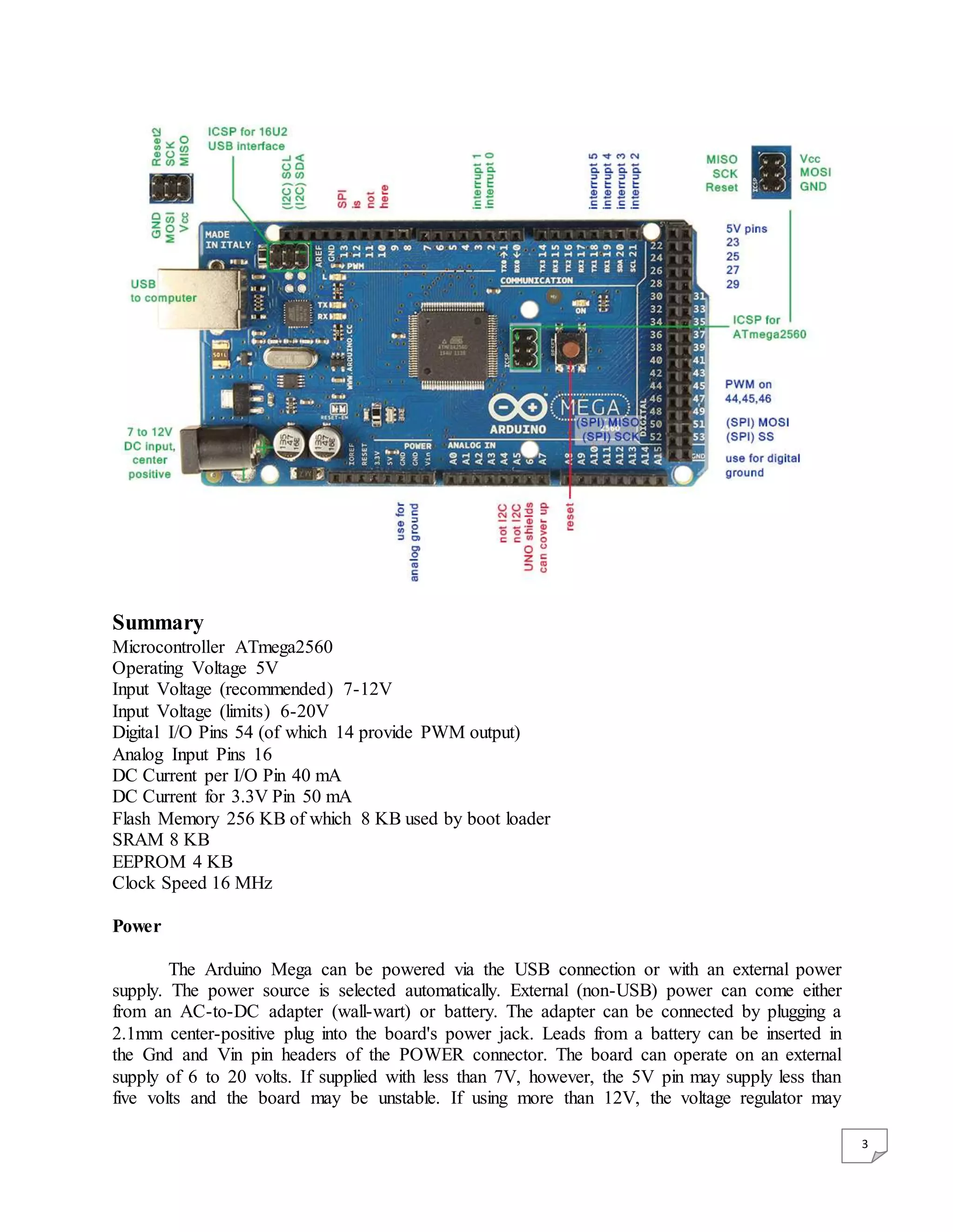
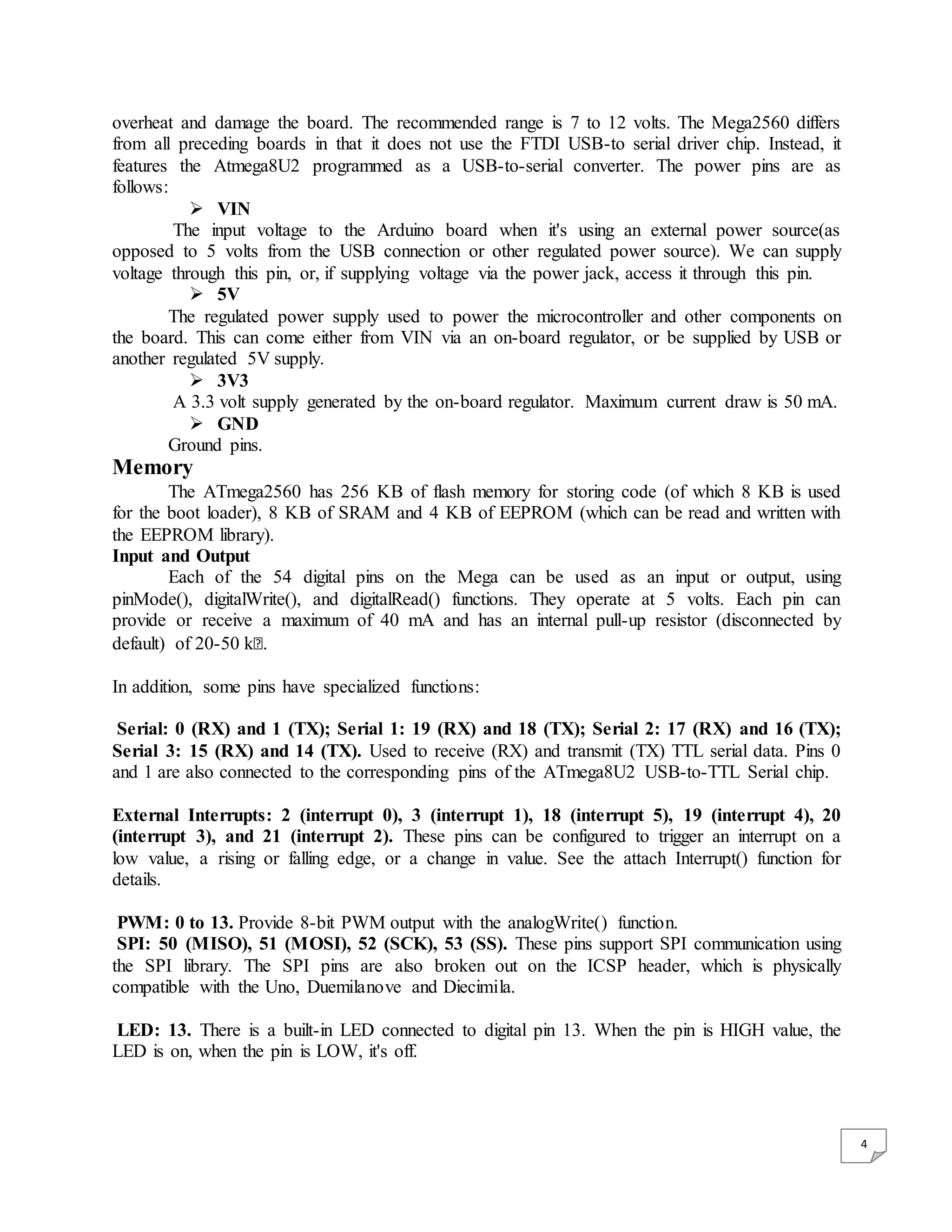
2 Chapter 2 Arduino Mega2560 2.1 Introduction The Arduino Mega 2560 is a microcontroller board based on the ATmega2560. It has 54 digital input/output pins (of which 14 can be used as PWM outputs), 16 analog inputs, 4 UARTs (hardware serial ports), a 16 MHz crystal oscillator, a USB connection, a power jack, an ICSP header, and a reset button. It contains everything needed to support the microcontroller; simply connect it to a computer with a USB cable or power it with a AC to DC adapter or battery to get started. The Mega is compatible with most shields designed for the Arduino Duemilanove or Diecimila. Arduino board designs use a variety of microprocessors and controllers. The boards are equipped with sets of digital and analog input/output (I/O) pins that may be interfaced to various expansion boards and other circuits. The boards feature serial communications interfaces, including Universal Serial Bus (USB) on some models, which are also used for loading programs from personal computers. The microcontrollers are typically programmed using a dialect of features from the programming languages C and C++. In addition to using traditional compiler tool chains, the Arduino project provides an integrated development environment (IDE) based on the Processing language project. The Arduino project started in 2003 as a program for students at the Interaction Design Institute Ivrea in Ivrea, Italy, aiming to provide a low-cost and easy way for novices and professionals to create devices that interact with their environment using sensors and actuators. Common examples of such devices intended for beginner hobbyists include simple robots, thermostats, and motion detectors. The name Arduino comes from a bar in Ivrea, Italy, where some of the founders of the project used to meet. The bar was named after Arduino of Ivrea, who was the margrave of the March of Ivrea and King of Italy from 1002 to 1014
3.
3 Summary Microcontroller ATmega2560 Operating Voltage5V Input Voltage (recommended) 7-12V Input Voltage (limits) 6-20V Digital I/O Pins 54 (of which 14 provide PWM output) Analog Input Pins 16 DC Current per I/O Pin 40 mA DC Current for 3.3V Pin 50 mA Flash Memory 256 KB of which 8 KB used by boot loader SRAM 8 KB EEPROM 4 KB Clock Speed 16 MHz Power The Arduino Mega can be powered via the USB connection or with an external power supply. The power source is selected automatically. External (non-USB) power can come either from an AC-to-DC adapter (wall-wart) or battery. The adapter can be connected by plugging a 2.1mm center-positive plug into the board's power jack. Leads from a battery can be inserted in the Gnd and Vin pin headers of the POWER connector. The board can operate on an external supply of 6 to 20 volts. If supplied with less than 7V, however, the 5V pin may supply less than five volts and the board may be unstable. If using more than 12V, the voltage regulator may
4.
4 overheat and damagethe board. The recommended range is 7 to 12 volts. The Mega2560 differs from all preceding boards in that it does not use the FTDI USB-to serial driver chip. Instead, it features the Atmega8U2 programmed as a USB-to-serial converter. The power pins are as follows: VIN The input voltage to the Arduino board when it's using an external power source(as opposed to 5 volts from the USB connection or other regulated power source). We can supply voltage through this pin, or, if supplying voltage via the power jack, access it through this pin. 5V The regulated power supply used to power the microcontroller and other components on the board. This can come either from VIN via an on-board regulator, or be supplied by USB or another regulated 5V supply. 3V3 A 3.3 volt supply generated by the on-board regulator. Maximum current draw is 50 mA. GND Ground pins. Memory The ATmega2560 has 256 KB of flash memory for storing code (of which 8 KB is used for the boot loader), 8 KB of SRAM and 4 KB of EEPROM (which can be read and written with the EEPROM library). Input and Output Each of the 54 digital pins on the Mega can be used as an input or output, using pinMode(), digitalWrite(), and digitalRead() functions. They operate at 5 volts. Each pin can provide or receive a maximum of 40 mA and has an internal pull-up resistor (disconnected by default) of 20-50 kꭥ. In addition, some pins have specialized functions: Serial: 0 (RX) and 1 (TX); Serial 1: 19 (RX) and 18 (TX); Serial 2: 17 (RX) and 16 (TX); Serial 3: 15 (RX) and 14 (TX). Used to receive (RX) and transmit (TX) TTL serial data. Pins 0 and 1 are also connected to the corresponding pins of the ATmega8U2 USB-to-TTL Serial chip. External Interrupts: 2 (interrupt 0), 3 (interrupt 1), 18 (interrupt 5), 19 (interrupt 4), 20 (interrupt 3), and 21 (interrupt 2). These pins can be configured to trigger an interrupt on a low value, a rising or falling edge, or a change in value. See the attach Interrupt() function for details. PWM: 0 to 13. Provide 8-bit PWM output with the analogWrite() function. SPI: 50 (MISO), 51 (MOSI), 52 (SCK), 53 (SS). These pins support SPI communication using the SPI library. The SPI pins are also broken out on the ICSP header, which is physically compatible with the Uno, Duemilanove and Diecimila. LED: 13. There is a built-in LED connected to digital pin 13. When the pin is HIGH value, the LED is on, when the pin is LOW, it's off.
5.
5 I2C: 20 (SDA)and 21 (SCL). Support I2C (TWI) communication using the Wire library (documentation on the Wiring website). Note that these pins are not in the same location as the I2C pins on the Duemilanove or Diecimila. The Mega2560 has 16 analog inputs, each of which provide 10 bits of resolution (i.e. 1024 different values). By default they measure from ground to 5 volts, though is it possible to change the upper end of their range using the AREF pin and analogReference() function. There are a couple of other pins on the board: AREF. Reference voltage for the analog inputs. Used with analogReference(). Reset. Bring this line LOW to reset the microcontroller. Typically used to add a reset button to shields which block the one on the board. Communication The Arduino Mega2560 has a number of facilities for communicating with a computer, another Arduino, or other microcontrollers. The ATmega2560 provides four hardware UARTs for TTL (5V) serial communication. An ATmega8U2 on the board channels one of these over USB and provides a virtual com port to software on the computer (Windows machines will need a .inf file, but OSX and Linux machines will recognize the board as a COM port automatically. The Arduino software includes a serial monitor which allows simple textual data to be sent to and from the board. The RX and TX LEDs on the board will flash when data is being transmitted via the ATmega8U2 chip and USB connection to the computer (but not for serial communication on pins 0 and 1). A Software Serial library allows for serial communication on any of the Mega2560's digital pins. The ATmega2560 also supports I2C (TWI) and SPI communication. The Arduino software includes a Wire library to simplify use of the I2C bus; see the documentation on the Wiring website for details. For SPI communication, use the SPI library. Programming The Arduino Mega can be programmed with the Arduino software (download). For details, see the reference and tutorials. The ATmega2560 on the Arduino Mega come pre burned with a boot loader that allows us to upload new code to it without the use of an external hardware programmer. It communicates using the original STK500 protocol (reference, C header files). We can also bypass the boot loader and program the microcontroller through the ICSP (In Circuit Serial Programming) header; see these instructions for details. Automatic (Software) Reset Rather then requiring a physical press of the reset button before an upload, the Arduino Mega2560 is designed in a way that allows it to be reset by software running on a connected computer. One of the hardware flow control lines (DTR) of the ATmega8U2 is connected to the reset line of the ATmega2560 via a 100 nano farad capacitor. When this line is asserted (taken
6.
6 low), the resetline drops long enough to reset the chip. The Arduino software uses this capability to allow you to upload code by simply pressing the upload button in the Arduino environment. This means that the boot loader can have a shorter timeout, as the lowering of DTR can be well- coordinated with the start of the upload. This setup has other implications. When the Mega2560 is connected to either a computer running Mac OS X or Linux, it resets each time a connection is made to it from software (via USB). For the following half-second or so, the bootloader is running on the Mega2560. While it is programmed to ignore malformed data (i.e. anything besides an upload of new code), it will intercept the first few bytes of data sent to the board after a connection is opened. If a sketch running on the board receives one-time configuration or other data when it first starts, make sure that the software with which it communicates waits a second after opening the connection and before sending this data. The Mega2560 contains a trace that can be cut to disable the auto-reset. The pads on either side of the trace can be soldered together to re-enable it. It's labeled "RESET-EN". You may also be able to disable the auto-reset by connecting a 110 ohm resistor from 5V to the reset line; see this forum thread for details. USB Over current Protection The Arduino Mega2560 has a resettable poly fuse that protects your computer's USB ports from shorts and over current. Although most computers provide their own internal protection, the fuse provides an extra layer of protection. If more than 500 mA is applied to the USB port, the fuse will automatically break the connection until the short or overload is removed. Physical Characteristics and Shield Compatibility The maximum length and width of the Mega2560 PCB are 4 and 2.1 inches respectively, with the USB connector and power jack extending beyond the former dimension. Three screw holes allow the board to be attached to a surface or case. Note that the distance between digital pins 7 and 8 is 160 mil (0.16"), not an even multiple of the 100 mil spacing of the other pins. The Mega2560 is designed to be compatible with most shields designed for the Uno, Diecimila or Duemilanove. Digital pins 0 to 13 (and the adjacent AREF and GND pins), analog inputs 0 to 5, the power header, and ICSP header are all in equivalent locations. Further the main UART (serial port) is located on the same pins (0 and 1), as are external interrupts 0 and 1 (pins 2 and 3 respectively). SPI is available through the ICSP header on both the Mega2560 and Duemilanove / Diecimila. Please note that I2C is not located on the same pins on the Mega (20 and 21) as the Duemilanove / Diecimila (analog inputs 4 and 5).
8 2.2 Arduino Software(IDE) The Arduino Integrated Development Environment - or Arduino Software (IDE) - contains a text editor for writing code, a message area, a text console, a toolbar with buttons for common functions and a series of menus. It connects to the Arduino and Genuino hardware to upload programs and communicate with them. Writing Sketches Programs written using Arduino Software (IDE) are called sketches. These sketches are written in the text editor and are saved with the file extension .ino. The editor has features for cutting/pasting and for searching/replacing text. The message area gives feedback while saving and exporting and also displays errors. The console displays text output by the Arduino Software (IDE), including complete error messages and other information. The bottom right hand corner of the window displays the configured board and serial port. The toolbar buttons allow you to verify and upload programs, create, open, and save sketches, and open the serial monitor. NB: Versions of the Arduino Software (IDE) prior to 1.0 saved sketches with the extension .pde. It is possible to open these files with version 1.0, you will be prompted to save the sketch with the .ino extension on save. Verify Checks your code for errors compiling it. Upload Compiles your code and uploads it to the configured board. See uploading below for details. Note: If you are using an external programmer with your board, you can hold down the "shift" key on your computer when using this icon. The text will change to "Upload using Programmer" New Creates a new sketch. Open Presents a menu of all the sketches in your sketchbook. Clicking one will open it within the current window overwriting its content. Note: due to a bug in Java, this menu doesn't scroll; if you need to open a sketch late in the list, use the File | Sketchbook menu instead.
9.
9 Save Saves your sketch. SerialMonitor Opens the serial monitor. Additional commands are found within the five menus: File, Edit, Sketch, Tools, Help. The menus are context sensitive, which means only those items relevant to the work currently being carried out are available. File New Creates a new instance of the editor, with the bare minimum structure of a sketch already in place. Open Allows to load a sketch file browsing through the computer drives and folders. Open Recent Provides a short list of the most recent sketches, ready to be opened. Sketchbook Shows the current sketches within the sketchbook folder structure; clicking on any name opens the corresponding sketch in a new editor instance. Examples Any example provided by the Arduino Software (IDE) or library shows up in this menu item. All the examples are structured in a tree that allows easy access by topic or library. Close Closes the instance of the Arduino Software from which it is clicked. Save Saves the sketch with the current name. If the file hasn't been named before, a name will be provided in a "Save as.." window. Save as... Allows to save the current sketch with a different name. Page Setup It shows the Page Setup window for printing. Print Sends the current sketch to the printer according to the settings defined in Page Setup. Preferences Opens the Preferences window where some settings of the IDE may be customized, as the language of the IDE interface. Quit Closes all IDE windows. The same sketches open when Quit was chosen will be automatically reopened the next time you start the IDE.
10.
10 Edit Undo/Redo Goes backof one or more steps you did while editing; when you go back, you may go forward with Redo. Cut Removes the selected text from the editor and places it into the clipboard. Copy Duplicates the selected text in the editor and places it into the clipboard. Copy for Forum Copies the code of your sketch to the clipboard in a form suitable for posting to the forum, complete with syntax coloring. Copy as HTML Copies the code of your sketch to the clipboard as HTML, suitable for embedding in web pages. Paste Puts the contents of the clipboard at the cursor position, in the editor. Select All Selects and highlights the whole content of the editor. Comment/Uncomment Puts or removes the // comment marker at the beginning of each selected line. Increase/Decrease Indent Adds or subtracts a space at the beginning of each selected line, moving the text one space on the right or eliminating a space at the beginning. Find Opens the Find and Replace window where you can specify text to search inside the current sketch according to several options. Find Next Highlights the next occurrence - if any - of the string specified as the search item in the Find window, relative to the cursor position. Find Previous Highlights the previous occurrence - if any - of the string specified as the search item in the Find window relative to the cursor position. Sketch Verify/Compile Checks your sketch for errors compiling it; it will report memory usage for code and variables in the console area. Upload Compiles and loads the binary file onto the configured board through the configured Port. Upload Using Programmer This will overwrite the bootloader on the board; you will need to use Tools > Burn Bootloader to restore it and be able to Upload to USB serial port again. However, it allows you to use the full capacity of the Flash memory for your sketch. Please note that this command will NOT burn the fuses. To do so a Tools -> Burn Bootloader command must be executed.
11.
11 Export CompiledBinary Saves a .hex file that may be kept as archive or sent to the board using other tools. Show Sketch Folder Opens the current sketch folder. Include Library Adds a library to your sketch by inserting #include statements at the start of your code. For more details, see libraries below. Additionally, from this menu item you can access the Library Manager and import new libraries from .zip files. Add File... Adds a source file to the sketch (it will be copied from its current location). The new file appears in a new tab in the sketch window. Files can be removed from the sketch using the tab menu accessible clicking on the small triangle icon below the serial monitor one on the right side o the toolbar. Tools Auto Format This formats your code nicely: i.e. indents it so that opening and closing curly braces line up, and that the statements inside curly braces are indented more. Archive Sketch Archives a copy of the current sketch in .zip format. The archive is placed in the same directory as the sketch. Fix Encoding & Reload Fixes possible discrepancies between the editor char map encoding and other operating systems char maps. Serial Monitor Opens the serial monitor window and initiates the exchange of data with any connected board on the currently selected Port. This usually resets the board, if the board supports Reset over serial port opening. Board Select the board that you're using. See below for descriptions of the various boards. Port This menu contains all the serial devices (real or virtual) on your machine. It should automatically refresh every time you open the top-level tools menu. Programmer For selecting a harware programmer when programming a board or chip and not using the onboard USB-serial connection. Normally you won't need this, but if you're burning a boot loader to a new microcontroller, you will use this. Burn Boot loader The items in this menu allow you to burn a bootloader onto the microcontroller on an Arduino board. This is not required for normal use of an Arduino or Genuino board but is useful if you purchase a new ATmega microcontroller (which normally come without a bootloader). Ensure that you've selected the correct board from the Boards menu before burning the bootloader on the target board. This command also set the right fuses.
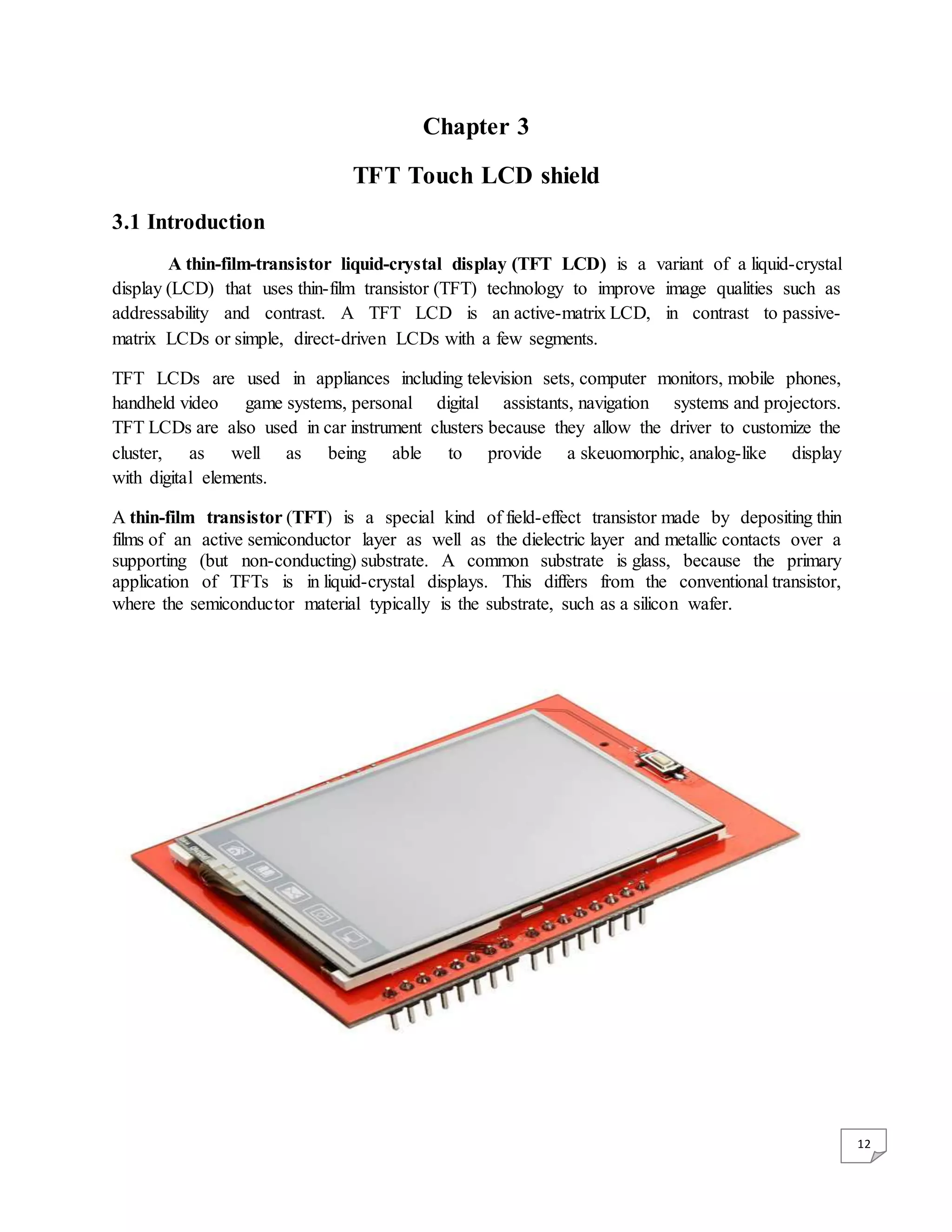
12.
12 Chapter 3 TFT TouchLCD shield 3.1 Introduction A thin-film-transistor liquid-crystal display (TFT LCD) is a variant of a liquid-crystal display (LCD) that uses thin-film transistor (TFT) technology to improve image qualities such as addressability and contrast. A TFT LCD is an active-matrix LCD, in contrast to passive- matrix LCDs or simple, direct-driven LCDs with a few segments. TFT LCDs are used in appliances including television sets, computer monitors, mobile phones, handheld video game systems, personal digital assistants, navigation systems and projectors. TFT LCDs are also used in car instrument clusters because they allow the driver to customize the cluster, as well as being able to provide a skeuomorphic, analog-like display with digital elements. A thin-film transistor (TFT) is a special kind of field-effect transistor made by depositing thin films of an active semiconductor layer as well as the dielectric layer and metallic contacts over a supporting (but non-conducting) substrate. A common substrate is glass, because the primary application of TFTs is in liquid-crystal displays. This differs from the conventional transistor, where the semiconductor material typically is the substrate, such as a silicon wafer.
13.
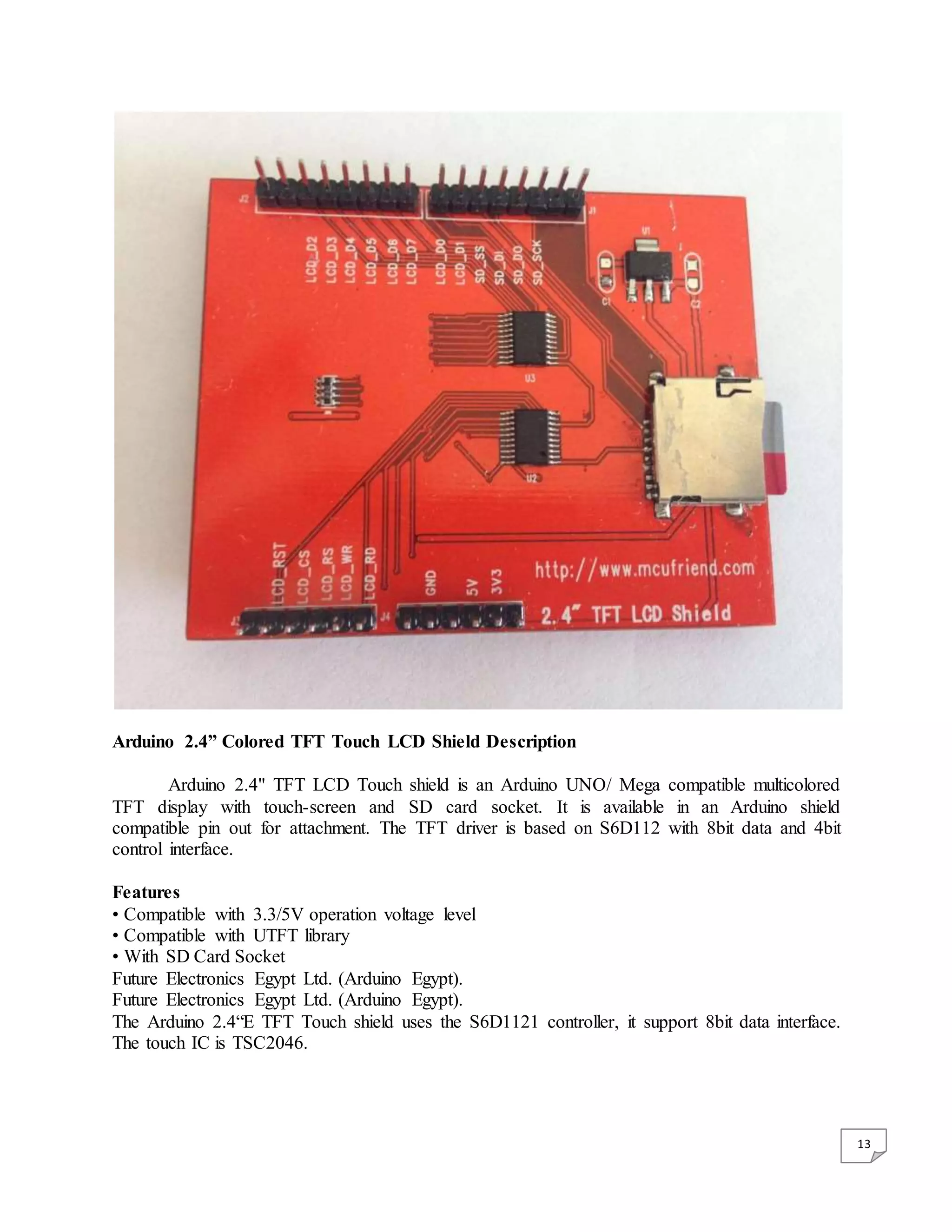
13 Arduino 2.4” ColoredTFT Touch LCD Shield Description Arduino 2.4" TFT LCD Touch shield is an Arduino UNO/ Mega compatible multicolored TFT display with touch-screen and SD card socket. It is available in an Arduino shield compatible pin out for attachment. The TFT driver is based on S6D112 with 8bit data and 4bit control interface. Features • Compatible with 3.3/5V operation voltage level • Compatible with UTFT library • With SD Card Socket Future Electronics Egypt Ltd. (Arduino Egypt). Future Electronics Egypt Ltd. (Arduino Egypt). The Arduino 2.4“E TFT Touch shield uses the S6D1121 controller, it support 8bit data interface. The touch IC is TSC2046.
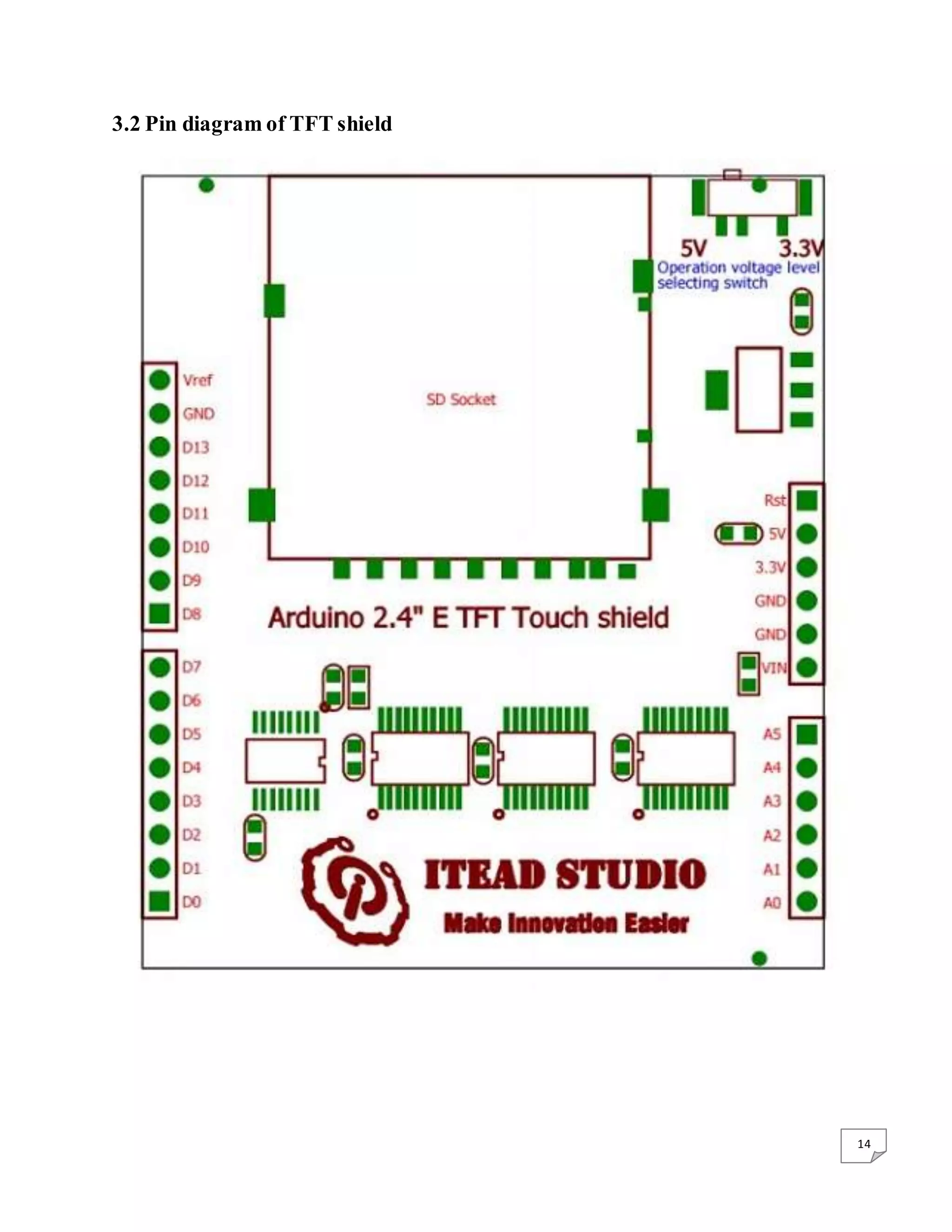
15 Operation voltage levelsetting switch When using the Arduino 2.4”E TFT Touch shield with 5V operation level development board – like the Arduino UNO, Arduino MEGA and so on, set the operation voltage level switch to 5V side. When using the Arduino 2.4“E TFT Touch shield with 3.3V operation level development board – like the Iteaduino BT, leaf maple, chipKit UNO and so on, set the operation voltage level switch to 3.3V side. 3.3 Construction diagram of the pixel layout
16.
16 The liquid crystaldisplays used in calculators and other devices with similarly simple displays have direct-driven image elements, and therefore a voltage can be easily applied across just one segment of these types of displays without interfering with the other segments. This would be impractical for a large display, because it would have a large number of (color) picture elements (pixels), and thus it would require millions of connections, both top and bottom for each one of the three colors (red, green and blue) of every pixel. To avoid this issue, the pixels are addressed in rows and columns, reducing the connection count from millions down to thousands. The column and row wires attach to transistor switches, one for each pixel. The one- way current passing characteristic of the transistor prevents the charge that is being applied to each pixel from being drained between refreshes to a display's image. Each pixel is a small capacitor with a layer of insulating liquid crystal sandwiched between transparent conductive ITO layers. The circuit layout process of a TFT-LCD is very similar to that of semiconductor products. However, rather than fabricating the transistors from silicon, that is formed into a crystalline silicon wafer, they are made from a thin film of amorphous silicon that is deposited on a glass panel. The silicon layer for TFT-LCDs is typically deposited using the PECVD process. Transistors take up only a small fraction of the area of each pixel and the rest of the silicon film is etched away to allow light to easily pass through it. Polycrystalline silicon is sometimes used in displays requiring higher TFT performance. Examples include small high-resolution displays such as those found in projectors or viewfinders. Amorphous silicon-based TFTs are by far the most common, due to their lower production cost, whereas polycrystalline silicon TFTs are more costly and much more difficult to produce. TFTs can be made using a wide variety of semiconductor materials. A common material is silicon. The characteristics of a silicon-based TFT depend on the silicon's crystalline state; that is, the semiconductor layer can be either amorphous silicon,[1] microcrystalline silicon, or it can be annealed into poly silicon. Other materials which have been used as semiconductors in TFTs include compound semiconductors such as cadmium selenide, or metal oxides such as zinc oxideor hafnium oxide. An application for hafnium oxide is as a high-κ dielectric. TFTs have also been made using organic materials, referred to as organic field-effect transistors OTFTs. By using transparent semiconductors and transparent electrodes, such as indium tin oxide (ITO), some TFT devices can be made completely transparent. Such transparent TFTs (TTFTs) can be used for construction of video display panels. Because conventional substrates cannot withstand high annealing temperatures, the deposition process must be completed under relatively low temperatures. Chemical vapor deposition and physical vapor deposition (usually sputtering) are applied. The first solution-processed TTFTs, based on zinc oxide, were reported in 2003 by researchers at Oregon State University.[4] The Portuguese laboratory CENIMAT at
17.
17 the Universidade Novade Lisboa has produced the world’s first completely transparent TFT at room temperature. CENIMAT also developed the first paper transistor, which may lead to applications such as magazines and journal pages with moving images. 3.4 Applications The best known application of thin-film transistors is in TFT LCDs, an implementation of LCD technology. Transistors are embedded within the panel itself, reducing cross talk between pixels and improving image stability. As of 2008, many color LCD TVs and monitors use this technology. TFT panels are frequently used in digital radiography applications in general radiography. A TFT is used in both direct and indirect capture as a base for the image receptor in medical radiography. AMOLED (active-matrix organic light-emitting diode) screens also contain a TFT layer. The most beneficial aspect of TFT technology is its use of a separate transistor for each pixel on the display. Because each transistor is small, the amount of charge needed to control it is also small. This allows for very fast re-drawing of the display.
18.
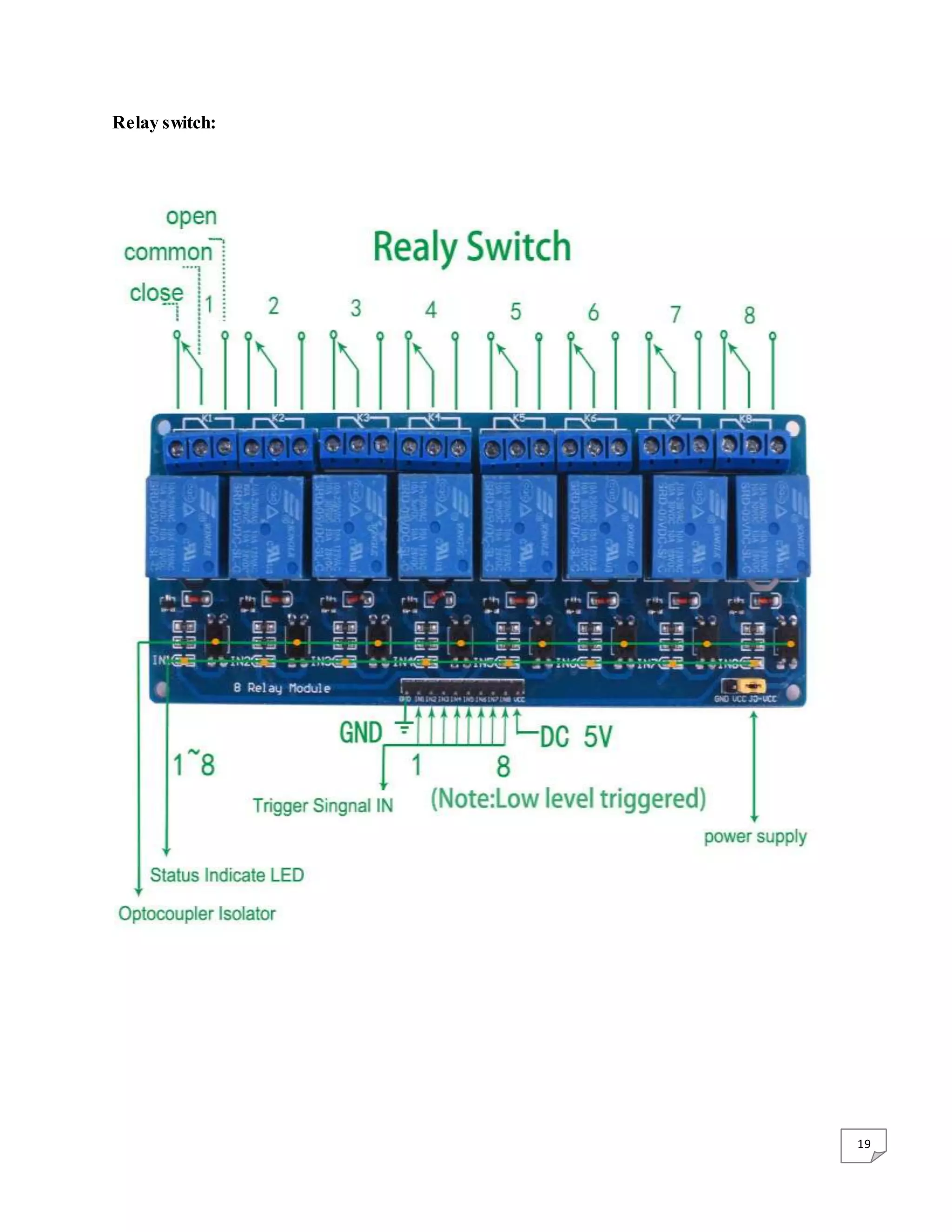
18 Chapter 4 Relay Module 4.1Introduction Arduino Relay Shield employs high quality relay with eight channels input and eight channels output. It can be connected to 250V/10A AC element or 24V/10A DC element to the maximum, therefore, it can be used to control lights, motors and etc. The modularized design makes it easy to connect to Arduino expansion board. The output state of the relay is shown by a luminous diode for the convenience of actual application. Specification Control signal: TTL voltage Rated load: 10A 250VAC 10A 125VAC 10A 30DC 10A 28VDC Rated Through-current: 10A(NO) 5A(NC) Max Switching Voltage: 250VAC 30VDC Contact actuation time: ﹤10ms Definition of module pins: Pin 1 -Pin 8----Controlling end Overview This is a 5V 8-Channels Relay module, It can be controlled directly by a wide range of microcontrollers such as Arduino, AVR, PIC, ARM and MSP430. 8 relays are included in this module, with “NC” ports means “Normally connected to COM” and “NO” ports means “Normally open to COM”. This module also equipped with 8 LEDS to show the status of relays. Features 8 mechanical relays with status indicator LED Both “NC” and “NO” ports for each relay
20 Chapter 5 Auxiliary Componentand Advantage of Project Auxiliary Component 1. Bulbs 2. Bulb holders 3. Male-female wire 4. Arduino USB cable 5. Circuit board 6. Adaptor for DC supply Advantages The switch is free from danger of electric shock. The switch can be made according to our requirement and can expand in future. It is free from mechanical error like block the switch due to any reason.
![16 The liquid crystal displays used in calculators and other devices with similarly simple displays have direct-driven image elements, and therefore a voltage can be easily applied across just one segment of these types of displays without interfering with the other segments. This would be impractical for a large display, because it would have a large number of (color) picture elements (pixels), and thus it would require millions of connections, both top and bottom for each one of the three colors (red, green and blue) of every pixel. To avoid this issue, the pixels are addressed in rows and columns, reducing the connection count from millions down to thousands. The column and row wires attach to transistor switches, one for each pixel. The one- way current passing characteristic of the transistor prevents the charge that is being applied to each pixel from being drained between refreshes to a display's image. Each pixel is a small capacitor with a layer of insulating liquid crystal sandwiched between transparent conductive ITO layers. The circuit layout process of a TFT-LCD is very similar to that of semiconductor products. However, rather than fabricating the transistors from silicon, that is formed into a crystalline silicon wafer, they are made from a thin film of amorphous silicon that is deposited on a glass panel. The silicon layer for TFT-LCDs is typically deposited using the PECVD process. Transistors take up only a small fraction of the area of each pixel and the rest of the silicon film is etched away to allow light to easily pass through it. Polycrystalline silicon is sometimes used in displays requiring higher TFT performance. Examples include small high-resolution displays such as those found in projectors or viewfinders. Amorphous silicon-based TFTs are by far the most common, due to their lower production cost, whereas polycrystalline silicon TFTs are more costly and much more difficult to produce. TFTs can be made using a wide variety of semiconductor materials. A common material is silicon. The characteristics of a silicon-based TFT depend on the silicon's crystalline state; that is, the semiconductor layer can be either amorphous silicon,[1] microcrystalline silicon, or it can be annealed into poly silicon. Other materials which have been used as semiconductors in TFTs include compound semiconductors such as cadmium selenide, or metal oxides such as zinc oxideor hafnium oxide. An application for hafnium oxide is as a high-κ dielectric. TFTs have also been made using organic materials, referred to as organic field-effect transistors OTFTs. By using transparent semiconductors and transparent electrodes, such as indium tin oxide (ITO), some TFT devices can be made completely transparent. Such transparent TFTs (TTFTs) can be used for construction of video display panels. Because conventional substrates cannot withstand high annealing temperatures, the deposition process must be completed under relatively low temperatures. Chemical vapor deposition and physical vapor deposition (usually sputtering) are applied. The first solution-processed TTFTs, based on zinc oxide, were reported in 2003 by researchers at Oregon State University.[4] The Portuguese laboratory CENIMAT at](https://image.slidesharecdn.com/projectfile-180208045427/75/Touch-Switch-Smart-Switches-by-arduino-Project-report-file-16-2048.jpg)