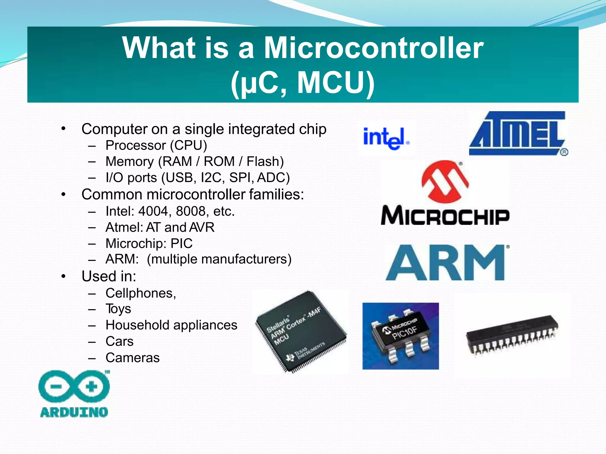
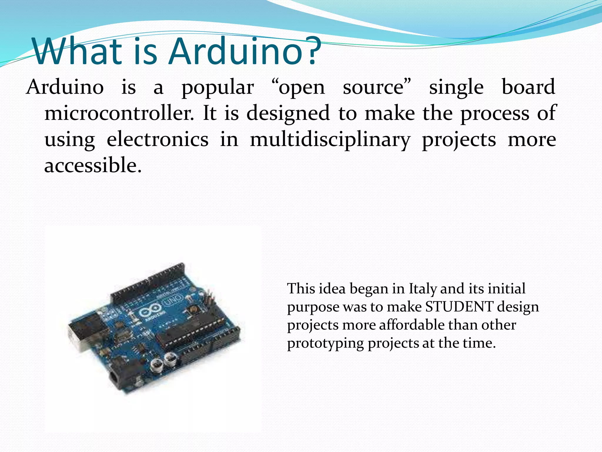
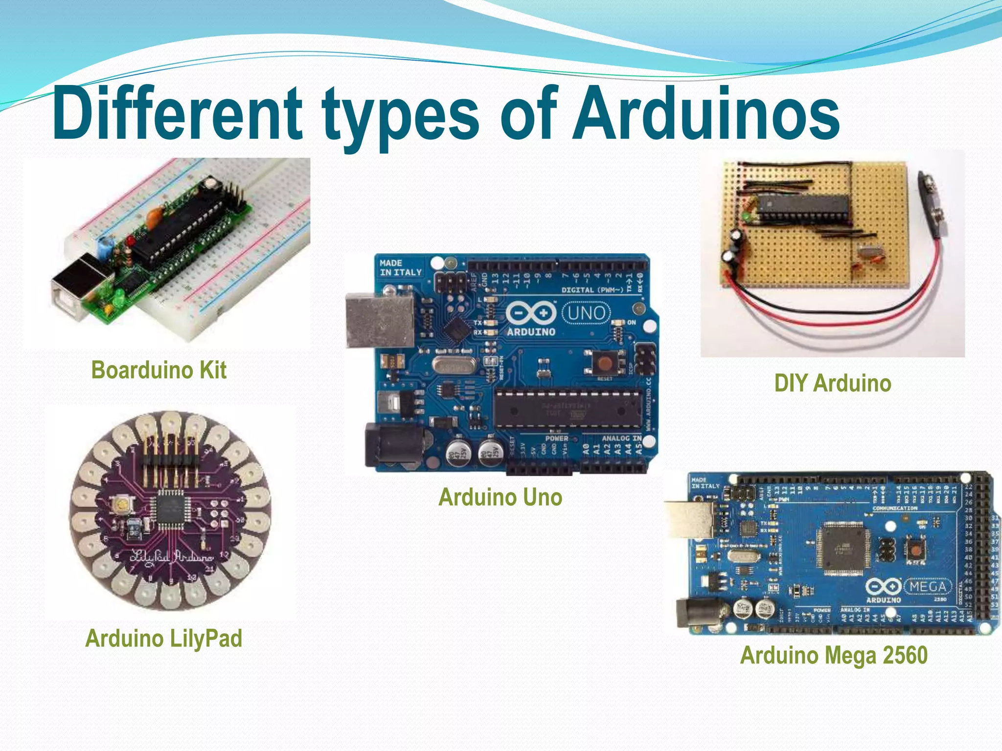
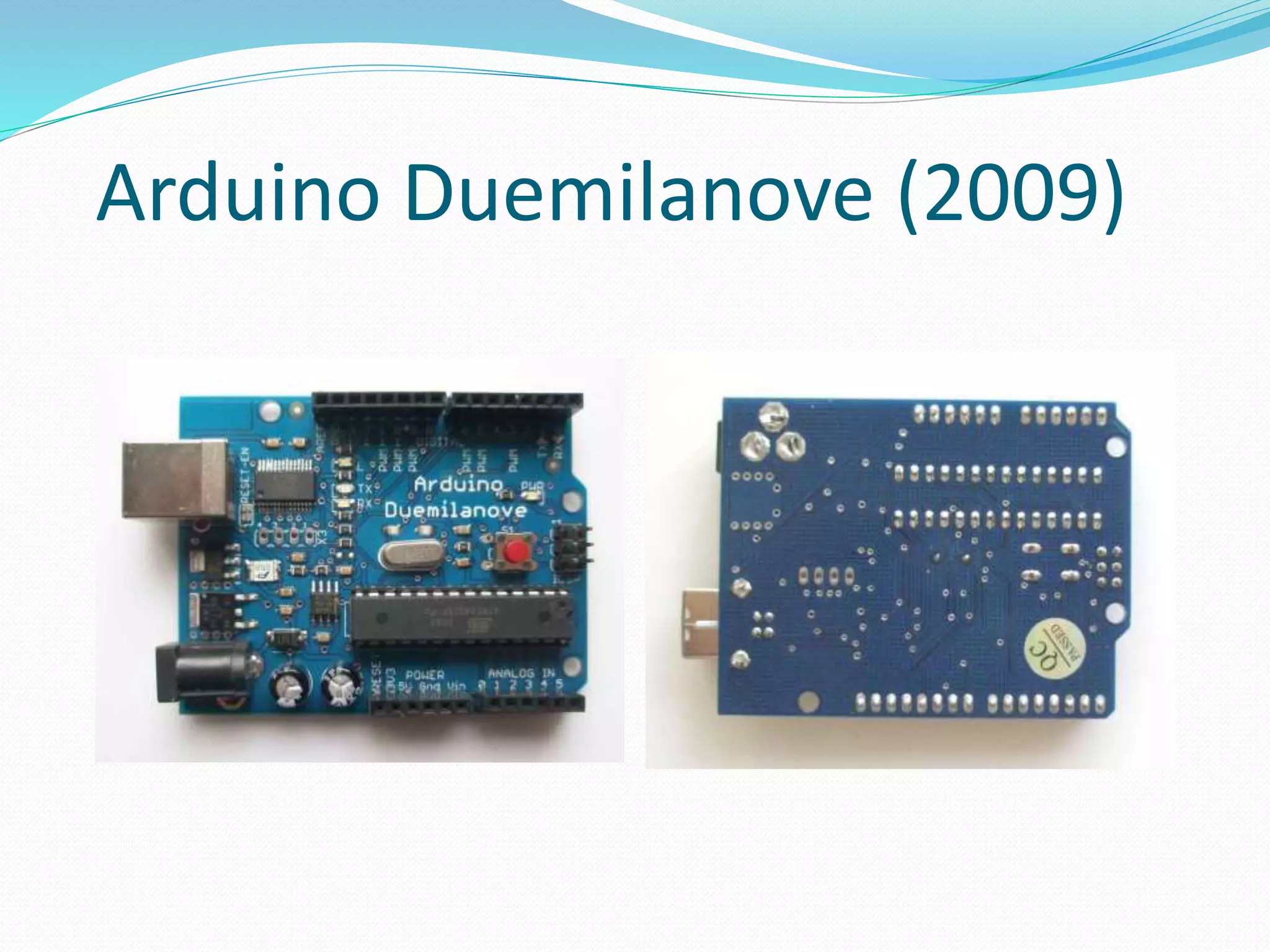
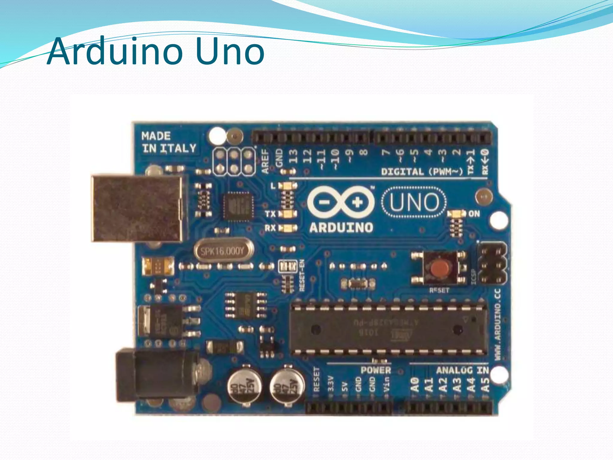
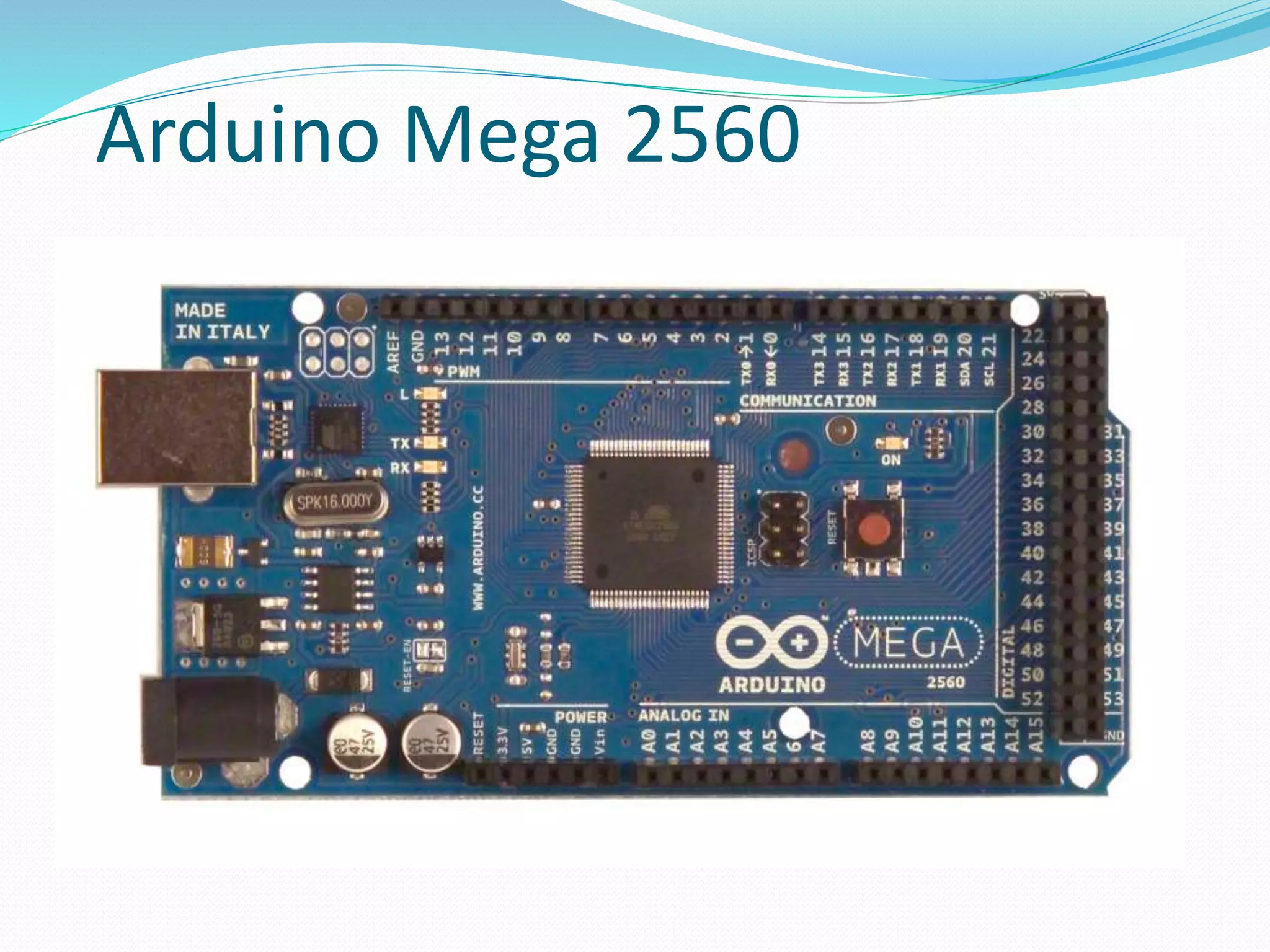
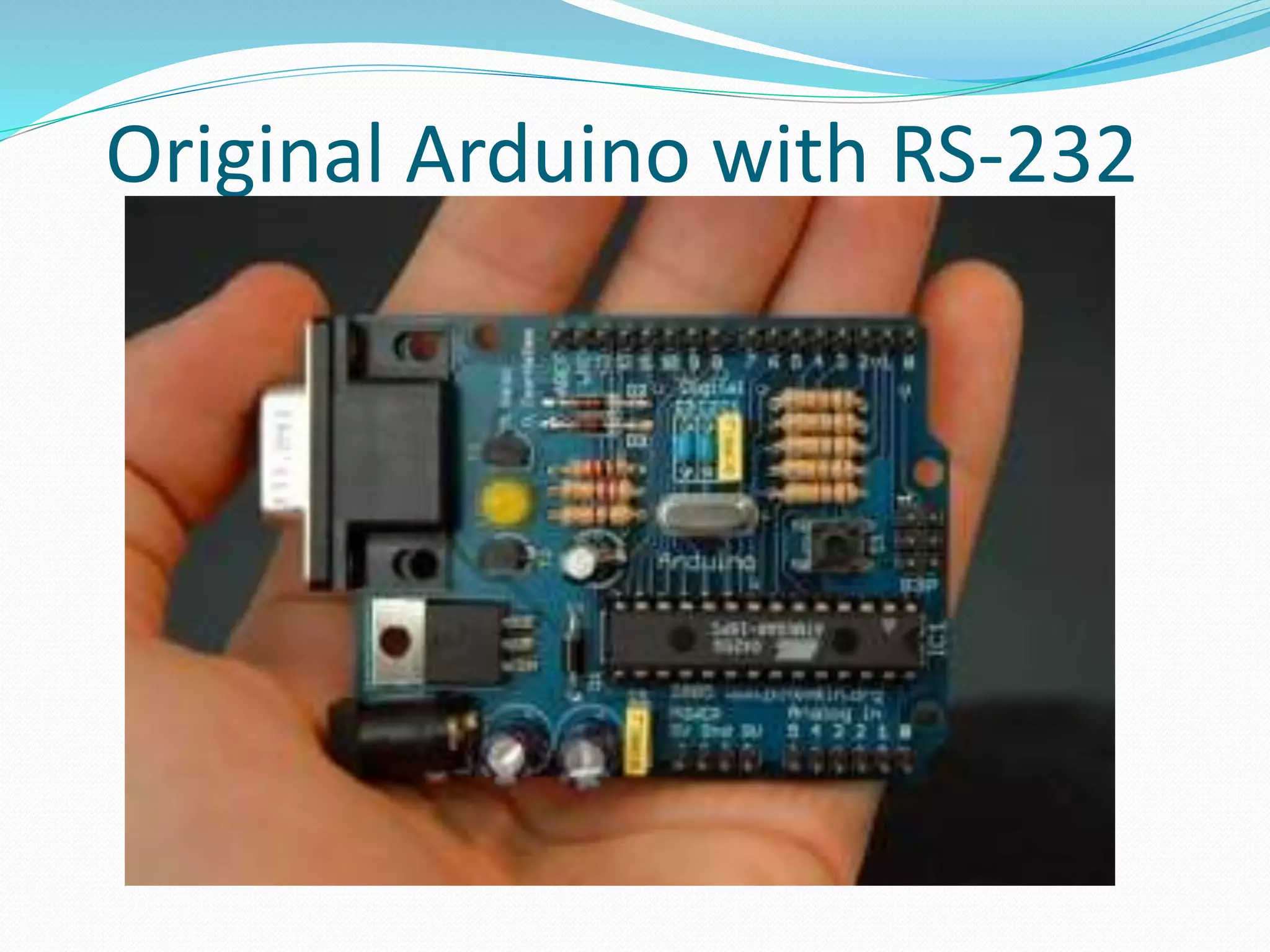
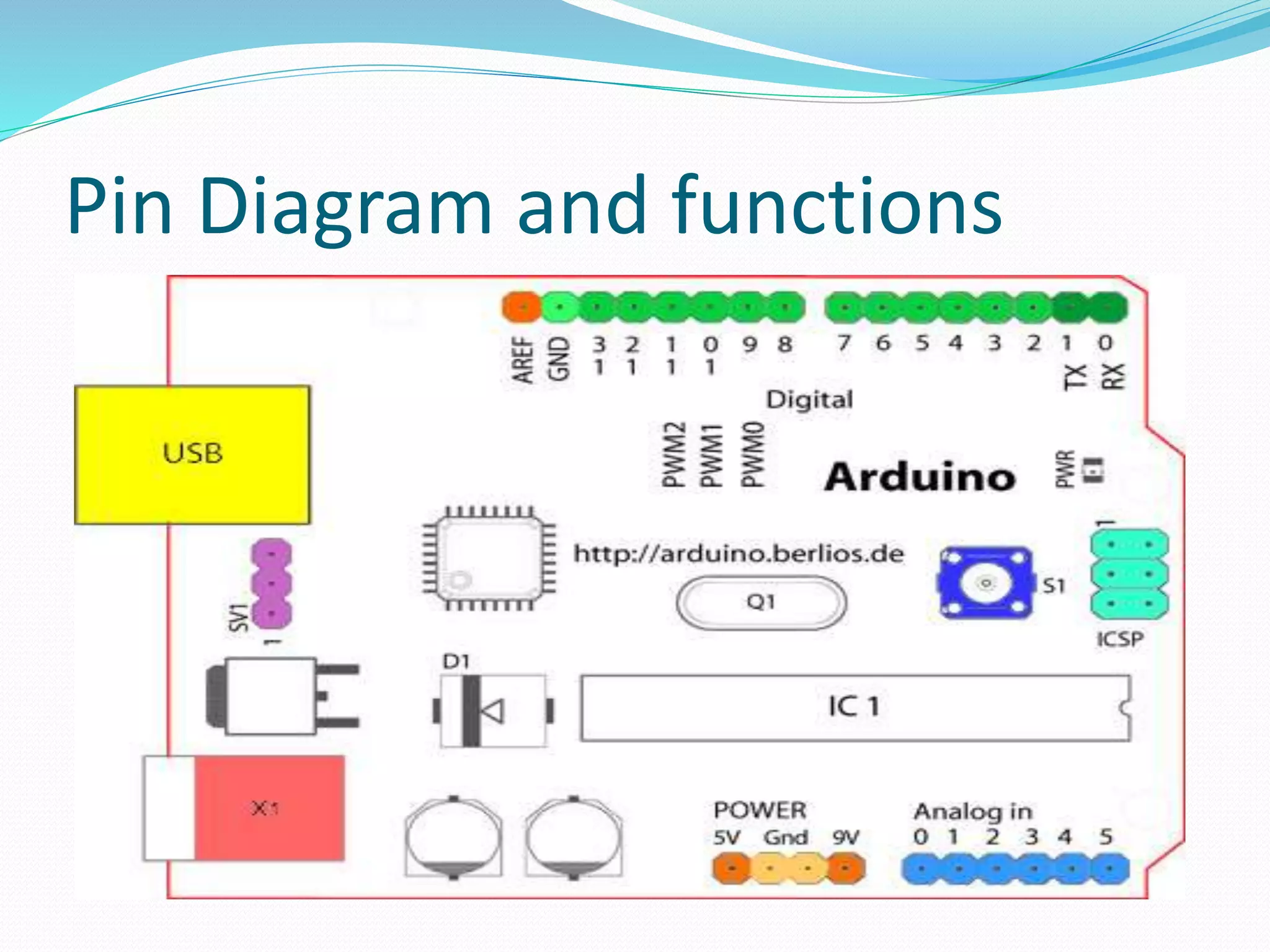
Prepared By: D. Y. Vankawala
What is a Microcontroller (µC, MCU) Computer on a single integrated chip• – – – Processor (CPU) Memory (RAM / ROM / Flash) I/O ports (USB, I2C, SPI, ADC) • Common microcontroller families: – – – – Intel: 4004, 8008, etc. Atmel: AT and AVR Microchip: PIC ARM: (multiple manufacturers) • Used in: – – – – – Cellphones, Toys Household appliances Cars Cameras
Arduino Overview  The Arduino microcontroller is an easy to use yet powerful single board computer that has gained considerable traction in the hobby and professional market. The Arduino is open-source, which means hardware is reasonably priced and development software is free.  The Arduino project was started in Italy to develop low cost hardware for interaction design.  The Arduino hardware comes in several flavors. In the United States, Sparkfun (www.sparkfun.com) is a good source for Arduino hardware.  With the Arduino board, you can write programs and create interface circuits to read switches and other sensors, and to control motors and lights with very little effort.
Continue  The Arduino programming language is a simplified version of C/C++. If you know C, programming the Arduino will be familiar. If you do not know C, no need to worry as only a few commands are needed to perform useful functions. An important feature of the Arduino is that you can create a control program on the host PC, download it to the Arduino and it will run automatically. Remove the USB cable connection to the PC, and the program will still run from the top each time you push the reset button. Remove the battery and put the Arduino board in a closet for six months. When you reconnect the battery, the last program you stored will run. This means that you connect the board to the host PC to develop and debug your program, but once that is done, you no longer need the PC to run the program.
The ATmega328P Microcontroller (used by the Arduino) • • • • • • AVR 8-bit RISC architecture Available in DIP package Up to 20 MHz clock 32kB flash memory 1 kB SRAM 23 programmable I/O channels Six 10-bit ADC inputs Three timers/counters Six PWM outputs • • •
What is Arduino Not? • • • • • It It It It It is is is is is not not not not not a a a a a chip (IC) board (PCB) company or a manufacturer programming language computer architecture (although it involves all of these things...)
So what is Arduino? It’s a movement, not a microcontroller: • Founded by Massimo Banzi and David Cuartielles in 2005 Based on “Wiring Platform”, which dates 2003 Open-source hardware platform Open source development environment • to • • – Easy-to learn language and libraries (based on Wiring language) Integrated development environment (based on Processing programming environment) Available for Windows / Mac / Linux – –
What is Arduino? Arduino is a popular “open source” single board microcontroller. It is designed to make the process of using electronics in multidisciplinary projects more accessible. This idea began in Italy and its initial purpose was to make STUDENT design projects more affordable than other prototyping projects at the time.
Continue…  Open Source Hardware, you can make your own board, or buy one.  Cheap, easily available.  Open Source Software.  Very widespread, many projects openly available.  Extra HW (shields) available.
The Many Flavors of Arduino • • • • • • • • Arduino Arduino Arduino Arduino Arduino Arduino Arduino Arduino Uno Leonardo LilyPad Mega Nano Mini Mini Pro BT
Arduino-like Systems • • • Cortino (ARM) Xduino (ARM) LeafLabs Maple (ARM) BeagleBoard (Linux) Wiring Board (Arduino predecessor) • •
Arduino Add-ons (Shields) • • • • • • • • TFT Touch Screen Data logger Motor/Servo shield Ethernet shield Audio wave shield Cellular/GSM shield WiFi shield ...many more
Where to Get an Arduino Board • Purchase from worldwide) online vendor (available – – – ... Sparkfun Adafruit DFRobot or build your• own – PC board – Solderless breadboard http://itp.nyu.edu/physcomp/Tutorials/ArduinoBreadboard
Different types of Arduinos Arduino Mega 2560 Arduino LilyPad Arduino Uno DIY Arduino Boarduino Kit
Arduino Duemilanove (2009)
Arduino Uno
Arduino Mega 2560
Original Arduino with RS-232
Arduino on breadboard
Arduino Nano
Ardweeny
Other Hardware Choices-Sheilds  Xbee Shield The Xbee shield allows an Arduino board to communicate wirelessly using Zigbee. The module can communicate up to 100 feet indoors or 300 feet outdoors (with line-of-sight). It can be used as a serial/usb replacement or you can put it into a command mode and configure it for a variety of broadcast and mesh networking options. The Xbee shield was created in collaboration with Libelium, who developed it for use in their SquidBee motes (used for creating sensor networks).  Adafruit Servo/Stepper/DC Motor shield A shield that can control 2 hobby servos and up to 2 unipolar/bipolar stepper motors or 4 bi-directional DC motors.  Battery Shield A shield from Liquidware that connects to the back of the Arduino, with a USB- rechargable lithium ion battery that can power an Arduino for 14-28 hours depending on the circuit  Liquidware TouchShield OLED touch screen shield.
Continue  Adafruit Wave shield Plays any size 22KHz audio files from an SD memory card for music, effects and interactive sound art  Adafruit GPS & Datalogging shield Connects up a GPS module and can log location, time/date as well as sensor data to an SD memory flash card.  Adafruit XPort/Ethernet shield Allows use of an XPort module for connecting to the Internet as a client or server.
Continue…
Continue…  Liquidware TouchShield OLED touch screen shield.  Adafruit Servo/Stepper/DC Motor shield A shield that can control 2 hobby servos and up to 2 unipolar/bipolar stepper motors or 4 bi-directional DC motors.
Bluetooth to TTL 5V module
USB to TTL module
RS-232 to TTL module
Pin Diagram and functions
Pins on Arduino Starting clockwise from the top center:  Analog Reference pin (orange)  Digital Ground (light green)  Digital Pins 2-13 (green)  Digital Pins 0-1/Serial In/Out - TX/RX (dark green) - These pins cannot be used for digital i/o (digitalRead and digitalWrite) if you are also using serial communication (e.g. Serial.begin).  Reset Button - S1 (dark blue)  In-circuit Serial Programmer (blue-green)  Analog In Pins 0-5 (light blue)  Power and Ground Pins (power: orange, grounds: light orange)  External Power Supply In (9-12VDC) - X1 (pink)  Toggles External Power and USB Power (place jumper on two pins closest to desired supply) - SV1 (purple)  USB (used for uploading sketches to the board and for serial communication between the board and the computer; can be used to power the board) (yellow)
Digital Pins  In addition to the specific functions listed below, the digital pins on an Arduino board can be used for general purpose input and output via the pinMode(), digitalRead(), and digitalWrite() commands. Each pin has an internal pull-up resistor which can be turned on and off using digitalWrite() (w/ a value of HIGH or LOW, respectively) when the pin is configured as an input. The maximum current per pin is 40 mA.
 Serial: 0 (RX) and 1 (TX). Used to receive (RX) and transmit (TX) TTL serial data. On the Arduino Diecimila, these pins are connected to the corresponding pins of the FTDI USB-to-TTL Serial chip. On the Arduino BT, they are connected to the corresponding pins of the WT11 Bluetooth module. On the Arduino Mini and LilyPad Arduino, they are intended for use with an external TTL serial module (e.g. the Mini-USB Adapter).  External Interrupts: 2 and 3. These pins can be configured to trigger an interrupt on a low value, a rising or falling edge, or a change in value. See the attachInterrupt() function for details.  PWM: 3, 5, 6, 9, 10, and 11. Provide 8-bit PWM output with the analogWrite() function. On boards with an ATmega8, PWM output is available only on pins 9, 10, and 11.  Reset: 7. (Arduino BT-only) Connected to the reset line of the bluetooth module.  SPI: 10 (SS), 11 (MOSI), 12 (MISO), 13 (SCK). These pins support SPI communication, which, although provided by the underlying hardware. It allow serial communication with another interface by connecting it serially.  LED: 13. On the Diecimila and LilyPad, there is a built-in LED connected to digital pin 13. When the pin is HIGH value, the LED is on, when the pin is LOW, it's off.
Analog Pins In addition to the specific functions listed below, the analog input pins support 10-bit analog-to-digital conversion (ADC) using the analogRead() function. Most of the analog inputs can also be used as digital pins: analog input 0 as digital pin 14 through analog input 5 as digital pin 19. Analog inputs 6 and 7 (present on the Mini and BT) cannot be used as digital pins.  I2C: 4 (SDA) and 5 (SCL). Support I2C (TWI) communication using the Wire library
Power Pins  VIN (sometimes labelled "9V"). The input voltage to the Arduino board when it's using an external power source (as opposed to 5 volts from the USB connection or other regulated power source). You can supply voltage through this pin, or, if supplying voltage via the power jack, access it through this pin. Note that different boards accept different input voltages ranges, please see the documentation for your board. Also note that the LilyPad has no VIN pin and accepts only a regulated input.  5V. The regulated power supply used to power the microcontroller and other components on the board. This can come either from VIN via an on-board regulator, or be supplied by USB or another regulated 5V supply.  3V3. (Diecimila-only) A 3.3 volt supply generated by the on- board FTDI chip.  GND. Ground pins.
Other Pins  AREF. Reference voltage for the analog inputs. It provide the analog reference voltage for analog to digital conversion  Reset. (Diecimila-only) Bring this line LOW to reset the microcontroller. Typically used to add a reset button to shields which block the one on the board.
Block Diagram of arduino
Function of Each block  USB Plug: By using this plug we can download hex file of our program by connecting it with PC. It also provide supply to arduino board. This USB plug is connected with FTDI Chip internally  FTDI Chip: This chip is nothing but voltage level converter chip. This chip is used to convert USB voltage level to TTL level and vice versa.  Digital I/O and PWM section: This section is used as for general purpose input output usage. By using this section we can perform digital input and output functions. In this section some pins are also used as PWM output pins. It is used for PWM based application like servo motors.
Continue…  Serial Tx and Rx Section: These two pins are used for serial communication in arduino. It is internally connected with USB plug through FTDI chip.  Power Supply: Power supply section provide different voltage level to different part of arduino board. This part contain bridge rectifier and voltage regulator.  AVR Atmega CPU: This block is the heart of the controller. Generally Atmega 8, Atmega 16, Atmega 32, Atmega 328 controller are used in arduino board. This block execute all the fuctions that written in arduino program.  SPI Interface section: This section is used for serial peripheral interfacing.  Power Pins section: This section include various voltage level pins including ground pins.  Analog input section: We know that Atmega 8 CPU has inbuilt 6 channel 10 – bit ADC. This ADC can convert analog data from analog pin into digital. So, for taking analog value for digital conversion we have to use this section.
Circuit Diagram of Arduino
The Arduino Environment
Board Type
Serial Port / COM Port
The Environment
Parts of the Sketch
Comments • Comments can be anywhere • Comments created with // or /* and */ • // is used for single line comment. • /* */ is used for multiline comments • Comments do not affect code • You may not need comments, but think about the community!
//- Single line comment /* */ - Multiline comment { } – used to define a block of code that starts and ends. ; - used to define the end of a line of code. Programming Symbols
Math Operators = (assignment) makes something equal to something else. For example, x = 10*2, thus x = 20. % (modulo) – this gives the remainder when one number is divided by another. For example 12 % 10 gives 2. + (addition) - (subtraction) * (multiplication) / (division)
Comparison Operators These are used to make logical comparisons. == (equal to) - For example 12==10 is FALSE and 12 ==12 is TRUE. != (not equal to) - For example 12!=10 is TRUE and 12!=12 is FALSE. < (less than) > (greater than)
Control Structures These execute code based on CONDITIONS. Here are just a few. if(condition) { } else if (condition) { } else(condition) { } This will execute the code between the curly braces if the condition is true, and if not test the condition of the “else if”. If that is false , the “else” code will execute. for (int i =0; i < #repeats; i ++) { } Used when you would like to repeat a line of code a specific # of times. Often called a FOR LOOP.
Activity 1: LED Blink • Load the “Blink” example (FileExamplesBasicsBlink) Use pin 13 as digital output Set output high (+5V) Wait 1000 milliseconds Set output low (0V) • • Compile, then upload the program Congratulations! you are now blinkers! void setup() { // initialize the digital pin as an output. // Pin 13 has an LED connected on most Arduino boards: pinMode(13, OUTPUT); } void loop() { digitalWrite(13, HIGH); // set the LED on delay(1000); // wait for a second digitalWrite(13, LOW); // set the LED off delay(1000); // wait for a second }
Now connect your own LED Anatomy of an LED: Notes: • • Resistor is needed to limit current Resistor and LED may be interchanged (but polarity of LED is important) Pin 13 is special: has built-in resistor and LED Change program and upload http://www.wikipedia.org/ • •
Aside: Using a Solderless Breadboard Connected together 300 mils Connected together
Example: Using a Solderless Breadboard
Experimenting • Change the blink rate – how fast can the LED blink (before you no longer perceive the blinking?) can • How would you make the LED dimmer? – (...without changing the resistor?)
Digital Input: Reading and Buttons Switches Writing HIGH to an input pin: enables an internal pull-up resistor • • • Turn on/off LED based on switch Pin 12 reads Pin 12 reads LOW when switch is closed HIGH when switch is open (pull-up) Without the internal pull-up resistor, unconnected digital inputs could read either high or low void setup() { pinMode(11, OUTPUT); // Use pin 11 for digital out pinMode(12, INPUT); // Use pin 12 for digital input digitalWrite(12, HIGH); // Enable pull‐up resistor } void loop() { boolean state; state = digitalRead(12); // read state of pin 12 digitalWrite(11, state); // set state of pin 11 (LED) delay(100); // wait for a 1/10 second }
Activity 2: Seven-Segment Display Write a that program that counts from 0 9 and displays the result on a seven- segment LED display • to • Consider writing a function: void writeDigit(int n) that writes a single digit
Seven-Segment Display Table Useful: • bitRead(x,n) Get the value of the Example: nth bit of an integer x – bitRead(0x7E,7); // returns 1 (see table above) Digit ABCDEFG A B C D E F G 0 0×7E on on on on on on off 1 0×30 off on on off off off off 2 0×6D on on off on on off on 3 0×79 on on on on off off on 4 0×33 off on on off off on on 5 0×5B on off on on off on on 6 0×5F on off on on on on on 7 0×70 on on on off off off off 8 0×7F on on on on on on on 9 0×7B on on on on off on on
• • Serial Communication - Writing IMPORTANT: USB serial communication is shared with Arduino pins 0 and 1 (RX/TX) Initialize serial rate) Example: port for communication (and sets baud Note: Serial.end() command is usually unnecessary, unless you need to use pins 0 & 1 – Serial.begin(9600); // 9600 baud Format can be: BIN, HEX, OCT, or an integer specifying the number of digits to display Prints data to the serial Examples: port – – – – Serial.print(“Hi”); Serial.print(78); Serial.print(variable); Serial.print(78,BIN); // // // // print works works a string with with numbers, too variables 1001110will print • Same as Serial.print(), but with line-feed Serial.println(val) Serial.print(val), Serial.print(val,fmt) Serial.begin(baud)
Activity 3: Hello World! Serial Monitor: • Write an Arduino program that prints the message “Hello world” to the serial port ...whenever you press a switch/button Use the Serial Monitor to see the output (Ctrl-Shift-M) Try increasing baud rate • • • Make sure this agrees with your program, i.e., Serial.begin(9600);
Program for serial transmission
Serial Communication - Reading • Returns the number of bytes Example: if (Serial.available() > 0) data = Serial.read(); } available to be read, if any { To read data from serial port: • • • • letter = Serial.read() letters = Serial.readBytesUntil(character, buffer, length) number = Serial.parseInt() number = Serial.parseFloat() Serial.available()

Basics of open source embedded development board (

  • 1.
    Prepared By: D.Y. Vankawala
  • 2.
    What is aMicrocontroller (µC, MCU) Computer on a single integrated chip• – – – Processor (CPU) Memory (RAM / ROM / Flash) I/O ports (USB, I2C, SPI, ADC) • Common microcontroller families: – – – – Intel: 4004, 8008, etc. Atmel: AT and AVR Microchip: PIC ARM: (multiple manufacturers) • Used in: – – – – – Cellphones, Toys Household appliances Cars Cameras
  • 3.
    Arduino Overview  TheArduino microcontroller is an easy to use yet powerful single board computer that has gained considerable traction in the hobby and professional market. The Arduino is open-source, which means hardware is reasonably priced and development software is free.  The Arduino project was started in Italy to develop low cost hardware for interaction design.  The Arduino hardware comes in several flavors. In the United States, Sparkfun (www.sparkfun.com) is a good source for Arduino hardware.  With the Arduino board, you can write programs and create interface circuits to read switches and other sensors, and to control motors and lights with very little effort.
  • 4.
    Continue  The Arduinoprogramming language is a simplified version of C/C++. If you know C, programming the Arduino will be familiar. If you do not know C, no need to worry as only a few commands are needed to perform useful functions. An important feature of the Arduino is that you can create a control program on the host PC, download it to the Arduino and it will run automatically. Remove the USB cable connection to the PC, and the program will still run from the top each time you push the reset button. Remove the battery and put the Arduino board in a closet for six months. When you reconnect the battery, the last program you stored will run. This means that you connect the board to the host PC to develop and debug your program, but once that is done, you no longer need the PC to run the program.
  • 5.
    The ATmega328P Microcontroller (usedby the Arduino) • • • • • • AVR 8-bit RISC architecture Available in DIP package Up to 20 MHz clock 32kB flash memory 1 kB SRAM 23 programmable I/O channels Six 10-bit ADC inputs Three timers/counters Six PWM outputs • • •
  • 6.
    What is ArduinoNot? • • • • • It It It It It is is is is is not not not not not a a a a a chip (IC) board (PCB) company or a manufacturer programming language computer architecture (although it involves all of these things...)
  • 7.
    So what isArduino? It’s a movement, not a microcontroller: • Founded by Massimo Banzi and David Cuartielles in 2005 Based on “Wiring Platform”, which dates 2003 Open-source hardware platform Open source development environment • to • • – Easy-to learn language and libraries (based on Wiring language) Integrated development environment (based on Processing programming environment) Available for Windows / Mac / Linux – –
  • 8.
    What is Arduino? Arduinois a popular “open source” single board microcontroller. It is designed to make the process of using electronics in multidisciplinary projects more accessible. This idea began in Italy and its initial purpose was to make STUDENT design projects more affordable than other prototyping projects at the time.
  • 9.
    Continue…  Open SourceHardware, you can make your own board, or buy one.  Cheap, easily available.  Open Source Software.  Very widespread, many projects openly available.  Extra HW (shields) available.
  • 10.
    The Many Flavorsof Arduino • • • • • • • • Arduino Arduino Arduino Arduino Arduino Arduino Arduino Arduino Uno Leonardo LilyPad Mega Nano Mini Mini Pro BT
  • 11.
    Arduino-like Systems • • • Cortino (ARM) Xduino(ARM) LeafLabs Maple (ARM) BeagleBoard (Linux) Wiring Board (Arduino predecessor) • •
  • 12.
    Arduino Add-ons (Shields) • • • • • • • • TFTTouch Screen Data logger Motor/Servo shield Ethernet shield Audio wave shield Cellular/GSM shield WiFi shield ...many more
  • 13.
    Where to Getan Arduino Board • Purchase from worldwide) online vendor (available – – – ... Sparkfun Adafruit DFRobot or build your• own – PC board – Solderless breadboard http://itp.nyu.edu/physcomp/Tutorials/ArduinoBreadboard
  • 14.
    Different types ofArduinos Arduino Mega 2560 Arduino LilyPad Arduino Uno DIY Arduino Boarduino Kit
  • 15.
  • 16.
  • 17.
  • 18.
  • 19.
  • 20.
  • 21.
  • 22.
    Other Hardware Choices-Sheilds Xbee Shield The Xbee shield allows an Arduino board to communicate wirelessly using Zigbee. The module can communicate up to 100 feet indoors or 300 feet outdoors (with line-of-sight). It can be used as a serial/usb replacement or you can put it into a command mode and configure it for a variety of broadcast and mesh networking options. The Xbee shield was created in collaboration with Libelium, who developed it for use in their SquidBee motes (used for creating sensor networks).  Adafruit Servo/Stepper/DC Motor shield A shield that can control 2 hobby servos and up to 2 unipolar/bipolar stepper motors or 4 bi-directional DC motors.  Battery Shield A shield from Liquidware that connects to the back of the Arduino, with a USB- rechargable lithium ion battery that can power an Arduino for 14-28 hours depending on the circuit  Liquidware TouchShield OLED touch screen shield.
  • 23.
    Continue  Adafruit Waveshield Plays any size 22KHz audio files from an SD memory card for music, effects and interactive sound art  Adafruit GPS & Datalogging shield Connects up a GPS module and can log location, time/date as well as sensor data to an SD memory flash card.  Adafruit XPort/Ethernet shield Allows use of an XPort module for connecting to the Internet as a client or server.
  • 24.
  • 25.
    Continue…  Liquidware TouchShield OLEDtouch screen shield.  Adafruit Servo/Stepper/DC Motor shield A shield that can control 2 hobby servos and up to 2 unipolar/bipolar stepper motors or 4 bi-directional DC motors.
  • 26.
  • 27.
    USB to TTLmodule
  • 28.
  • 29.
    Pin Diagram andfunctions
  • 31.
    Pins on Arduino Startingclockwise from the top center:  Analog Reference pin (orange)  Digital Ground (light green)  Digital Pins 2-13 (green)  Digital Pins 0-1/Serial In/Out - TX/RX (dark green) - These pins cannot be used for digital i/o (digitalRead and digitalWrite) if you are also using serial communication (e.g. Serial.begin).  Reset Button - S1 (dark blue)  In-circuit Serial Programmer (blue-green)  Analog In Pins 0-5 (light blue)  Power and Ground Pins (power: orange, grounds: light orange)  External Power Supply In (9-12VDC) - X1 (pink)  Toggles External Power and USB Power (place jumper on two pins closest to desired supply) - SV1 (purple)  USB (used for uploading sketches to the board and for serial communication between the board and the computer; can be used to power the board) (yellow)
  • 32.
    Digital Pins  Inaddition to the specific functions listed below, the digital pins on an Arduino board can be used for general purpose input and output via the pinMode(), digitalRead(), and digitalWrite() commands. Each pin has an internal pull-up resistor which can be turned on and off using digitalWrite() (w/ a value of HIGH or LOW, respectively) when the pin is configured as an input. The maximum current per pin is 40 mA.
  • 33.
     Serial: 0(RX) and 1 (TX). Used to receive (RX) and transmit (TX) TTL serial data. On the Arduino Diecimila, these pins are connected to the corresponding pins of the FTDI USB-to-TTL Serial chip. On the Arduino BT, they are connected to the corresponding pins of the WT11 Bluetooth module. On the Arduino Mini and LilyPad Arduino, they are intended for use with an external TTL serial module (e.g. the Mini-USB Adapter).  External Interrupts: 2 and 3. These pins can be configured to trigger an interrupt on a low value, a rising or falling edge, or a change in value. See the attachInterrupt() function for details.  PWM: 3, 5, 6, 9, 10, and 11. Provide 8-bit PWM output with the analogWrite() function. On boards with an ATmega8, PWM output is available only on pins 9, 10, and 11.  Reset: 7. (Arduino BT-only) Connected to the reset line of the bluetooth module.  SPI: 10 (SS), 11 (MOSI), 12 (MISO), 13 (SCK). These pins support SPI communication, which, although provided by the underlying hardware. It allow serial communication with another interface by connecting it serially.  LED: 13. On the Diecimila and LilyPad, there is a built-in LED connected to digital pin 13. When the pin is HIGH value, the LED is on, when the pin is LOW, it's off.
  • 34.
    Analog Pins In additionto the specific functions listed below, the analog input pins support 10-bit analog-to-digital conversion (ADC) using the analogRead() function. Most of the analog inputs can also be used as digital pins: analog input 0 as digital pin 14 through analog input 5 as digital pin 19. Analog inputs 6 and 7 (present on the Mini and BT) cannot be used as digital pins.  I2C: 4 (SDA) and 5 (SCL). Support I2C (TWI) communication using the Wire library
  • 35.
    Power Pins  VIN(sometimes labelled "9V"). The input voltage to the Arduino board when it's using an external power source (as opposed to 5 volts from the USB connection or other regulated power source). You can supply voltage through this pin, or, if supplying voltage via the power jack, access it through this pin. Note that different boards accept different input voltages ranges, please see the documentation for your board. Also note that the LilyPad has no VIN pin and accepts only a regulated input.  5V. The regulated power supply used to power the microcontroller and other components on the board. This can come either from VIN via an on-board regulator, or be supplied by USB or another regulated 5V supply.  3V3. (Diecimila-only) A 3.3 volt supply generated by the on- board FTDI chip.  GND. Ground pins.
  • 36.
    Other Pins  AREF.Reference voltage for the analog inputs. It provide the analog reference voltage for analog to digital conversion  Reset. (Diecimila-only) Bring this line LOW to reset the microcontroller. Typically used to add a reset button to shields which block the one on the board.
  • 37.
  • 38.
    Function of Eachblock  USB Plug: By using this plug we can download hex file of our program by connecting it with PC. It also provide supply to arduino board. This USB plug is connected with FTDI Chip internally  FTDI Chip: This chip is nothing but voltage level converter chip. This chip is used to convert USB voltage level to TTL level and vice versa.  Digital I/O and PWM section: This section is used as for general purpose input output usage. By using this section we can perform digital input and output functions. In this section some pins are also used as PWM output pins. It is used for PWM based application like servo motors.
  • 39.
    Continue…  Serial Txand Rx Section: These two pins are used for serial communication in arduino. It is internally connected with USB plug through FTDI chip.  Power Supply: Power supply section provide different voltage level to different part of arduino board. This part contain bridge rectifier and voltage regulator.  AVR Atmega CPU: This block is the heart of the controller. Generally Atmega 8, Atmega 16, Atmega 32, Atmega 328 controller are used in arduino board. This block execute all the fuctions that written in arduino program.  SPI Interface section: This section is used for serial peripheral interfacing.  Power Pins section: This section include various voltage level pins including ground pins.  Analog input section: We know that Atmega 8 CPU has inbuilt 6 channel 10 – bit ADC. This ADC can convert analog data from analog pin into digital. So, for taking analog value for digital conversion we have to use this section.
  • 40.
  • 41.
  • 42.
  • 43.
    Serial Port /COM Port
  • 44.
  • 45.
  • 46.
    Comments • Comments canbe anywhere • Comments created with // or /* and */ • // is used for single line comment. • /* */ is used for multiline comments • Comments do not affect code • You may not need comments, but think about the community!
  • 47.
    //- Single linecomment /* */ - Multiline comment { } – used to define a block of code that starts and ends. ; - used to define the end of a line of code. Programming Symbols
  • 48.
    Math Operators = (assignment)makes something equal to something else. For example, x = 10*2, thus x = 20. % (modulo) – this gives the remainder when one number is divided by another. For example 12 % 10 gives 2. + (addition) - (subtraction) * (multiplication) / (division)
  • 49.
    Comparison Operators These areused to make logical comparisons. == (equal to) - For example 12==10 is FALSE and 12 ==12 is TRUE. != (not equal to) - For example 12!=10 is TRUE and 12!=12 is FALSE. < (less than) > (greater than)
  • 50.
    Control Structures These executecode based on CONDITIONS. Here are just a few. if(condition) { } else if (condition) { } else(condition) { } This will execute the code between the curly braces if the condition is true, and if not test the condition of the “else if”. If that is false , the “else” code will execute. for (int i =0; i < #repeats; i ++) { } Used when you would like to repeat a line of code a specific # of times. Often called a FOR LOOP.
  • 51.
    Activity 1: LEDBlink • Load the “Blink” example (FileExamplesBasicsBlink) Use pin 13 as digital output Set output high (+5V) Wait 1000 milliseconds Set output low (0V) • • Compile, then upload the program Congratulations! you are now blinkers! void setup() { // initialize the digital pin as an output. // Pin 13 has an LED connected on most Arduino boards: pinMode(13, OUTPUT); } void loop() { digitalWrite(13, HIGH); // set the LED on delay(1000); // wait for a second digitalWrite(13, LOW); // set the LED off delay(1000); // wait for a second }
  • 52.
    Now connect yourown LED Anatomy of an LED: Notes: • • Resistor is needed to limit current Resistor and LED may be interchanged (but polarity of LED is important) Pin 13 is special: has built-in resistor and LED Change program and upload http://www.wikipedia.org/ • •
  • 53.
    Aside: Using aSolderless Breadboard Connected together 300 mils Connected together
  • 54.
    Example: Using aSolderless Breadboard
  • 55.
    Experimenting • Change theblink rate – how fast can the LED blink (before you no longer perceive the blinking?) can • How would you make the LED dimmer? – (...without changing the resistor?)
  • 56.
    Digital Input: Reading andButtons Switches Writing HIGH to an input pin: enables an internal pull-up resistor • • • Turn on/off LED based on switch Pin 12 reads Pin 12 reads LOW when switch is closed HIGH when switch is open (pull-up) Without the internal pull-up resistor, unconnected digital inputs could read either high or low void setup() { pinMode(11, OUTPUT); // Use pin 11 for digital out pinMode(12, INPUT); // Use pin 12 for digital input digitalWrite(12, HIGH); // Enable pull‐up resistor } void loop() { boolean state; state = digitalRead(12); // read state of pin 12 digitalWrite(11, state); // set state of pin 11 (LED) delay(100); // wait for a 1/10 second }
  • 57.
    Activity 2: Seven-Segment Display Writea that program that counts from 0 9 and displays the result on a seven- segment LED display • to • Consider writing a function: void writeDigit(int n) that writes a single digit
  • 58.
    Seven-Segment Display Table Useful: •bitRead(x,n) Get the value of the Example: nth bit of an integer x – bitRead(0x7E,7); // returns 1 (see table above) Digit ABCDEFG A B C D E F G 0 0×7E on on on on on on off 1 0×30 off on on off off off off 2 0×6D on on off on on off on 3 0×79 on on on on off off on 4 0×33 off on on off off on on 5 0×5B on off on on off on on 6 0×5F on off on on on on on 7 0×70 on on on off off off off 8 0×7F on on on on on on on 9 0×7B on on on on off on on
  • 59.
    • • Serial Communication -Writing IMPORTANT: USB serial communication is shared with Arduino pins 0 and 1 (RX/TX) Initialize serial rate) Example: port for communication (and sets baud Note: Serial.end() command is usually unnecessary, unless you need to use pins 0 & 1 – Serial.begin(9600); // 9600 baud Format can be: BIN, HEX, OCT, or an integer specifying the number of digits to display Prints data to the serial Examples: port – – – – Serial.print(“Hi”); Serial.print(78); Serial.print(variable); Serial.print(78,BIN); // // // // print works works a string with with numbers, too variables 1001110will print • Same as Serial.print(), but with line-feed Serial.println(val) Serial.print(val), Serial.print(val,fmt) Serial.begin(baud)
  • 60.
    Activity 3: HelloWorld! Serial Monitor: • Write an Arduino program that prints the message “Hello world” to the serial port ...whenever you press a switch/button Use the Serial Monitor to see the output (Ctrl-Shift-M) Try increasing baud rate • • • Make sure this agrees with your program, i.e., Serial.begin(9600);
  • 61.
    Program for serialtransmission
  • 62.
    Serial Communication -Reading • Returns the number of bytes Example: if (Serial.available() > 0) data = Serial.read(); } available to be read, if any { To read data from serial port: • • • • letter = Serial.read() letters = Serial.readBytesUntil(character, buffer, length) number = Serial.parseInt() number = Serial.parseFloat() Serial.available()