Downloaded 15 times
![International Journal of Advanced Research in Engineering and Technology (IJARET), ISSN 0976 – 6480(Print), ISSN 0976 – 6499(Online) Volume 4, Issue 3, April (2013), © IAEME 16 (23) (24) (25,26) Since the magnetizing flux is now known, it is possible to estimate the magnetizing inductance using the known nonlinear inverse magnetizing curve Figure 2. Block diagram of experimental system (27, 28) The block diagram of online identification procedures of the magnetizing inductance is shown in Fig 3. The magnetizing curve of the machine was identified offline, as described in [21], and is represented with a suitable analytical function in per unit, of the form (29) Coefficients a and b of (29) were determined as a = 0.9 and b = 7. The rated magnetizing current is 0.85 A (rms), and the rated magnetizing flux is 0.84524 Wb (rms). The rated magnetizing inductance value is 0.9944 H. Using (29) and the given data, the required ˆLm is easily obtained. Figure 3 Block diagram of speed, stator resistance, and magnetizing inductance identification schemes](https://image.slidesharecdn.com/speedestimationerrorofsensorlessinductionmotordrivesusingsoftcomputingtechnique-130430233325-phpapp01/75/Speed-estimation-error-of-sensorless-induction-motor-drives-using-soft-computing-technique-4-2048.jpg)
![International Journal of Advanced Research in Engineering and Technology (IJARET), ISSN 0976 – 6480(Print), ISSN 0976 – 6499(Online) Volume 4, Issue 3, April (2013), © IAEME 18 Figure 7 Speed estimation error for +20% Rs error in the observer at 150 rad/s (Fuzzy Logic) Figure 8 Speed estimation error for +20% Rs error in the observer at 3 rad/s(Fuzzy Logic) VI. CONCLUSION In this paper, parallel speed and stator resistance identification schemes of sensor less induction motor drives have been introduced to overcome the problem of resistance variation. Estimation algorithms have been obtained based on a sliding mode current observer combined with Popov’s hyper stability theory. It has been found that activation of the stator resistance adaptation mechanism quickly compensates the initial error in the estimated stator resistance value and therefore eliminates the initial speed estimation error. As a consequence, the actual and estimated speeds become in very good agreement. The speed estimation error at different reference speeds is estimated and observed that the error decreased with decrease in the reference speed with PI control technique. This speed estimation error is further decreased with a different control technique i.e fuzzy logic with the same reference speeds. So, we conclude that the speed estimation error can b decreased with a better control technique i.e fuzzy logic rather the conventional PI control in this case. REFERENCES [1] J. Holtz, “Sensorless control of induction motor drives,” Proc. IEEE, vol. 90, no. 8, pp. 1359– 1394, Aug. 2002. [2] M. S. Zaky, M. M. Khater, H. Yasin, S. S. Shokralla, and A. El-Sabbe, “Speed-sensor less control of induction motor drives,” Eng. Res. J., vol. 30, no. 4, pp. 433–444, Oct. 2007.](https://image.slidesharecdn.com/speedestimationerrorofsensorlessinductionmotordrivesusingsoftcomputingtechnique-130430233325-phpapp01/75/Speed-estimation-error-of-sensorless-induction-motor-drives-using-soft-computing-technique-6-2048.jpg)
![International Journal of Advanced Research in Engineering and Technology (IJARET), ISSN 0976 – 6480(Print), ISSN 0976 – 6499(Online) Volume 4, Issue 3, April (2013), © IAEME 19 [3] Q. Gao, G. Asher, and M. Sumner, “Sensorless position and speed control of induction motors using high-frequency injection and without offline precommissioning,” IEEE Trans. Ind. Electron., vol. 54, no. 5, pp. 2474– 2481, Oct. 2007. [4] H. Tajima, G. Guidi, and H. Umida, “Consideration about problems and solutions of speed estimation method and parameter tuning for speed sensor less vector control of induction motor drives,” IEEE Trans. Ind. Appl., vol. 38, no. 5, pp. 1282–1289, Sep./Oct. 2002. [5] J. Holtz and J. Quan, “Sensorless vector control of induction motors at very low speed using a nonlinear inverter model and parameter identification,” IEEE Trans. Ind. Appl., vol. 38, no. 4, pp. 1087–1095, Jul./Aug. 2002. [6] G. Guidi and H. Umida, “A novel stator resistance estimation method for speed-sensor less induction motor drives,” IEEE Trans. Ind. Appl., vol. 36, no. 6, pp. 1619–1627, Nov./Dec. 2000. [7] A. B. Proca, A. Keyhani, and J. M. Miller, “Sensorless sliding-mode control of induction motors using operating condition dependent models,” IEEE Trans. Energy Convers., vol. 18, no. 2, pp. 205– 212, Jun. 2003. [8] A. B. Proca and A. Keyhani, “Sliding-mode flux observer with online rotor parameter estimation for induction motors,” IEEE Trans. Ind. Electron., vol. 54, no. 2, pp. 716–723, Apr. 2007. [9] D. P.Marcetic and S. N. Vukosavic, “Speed-sensorless AC drives with the rotor time constant parameter update,” IEEE Trans. Ind. Electron., vol. 54, no. 5, pp. 2618–2625, May 2007. [10] S. Maiti, C. Chakra borty, Y. Hori, and M. C. Ta, “Model reference adaptive controller-based rotor resistance and speed estimation techniques for vector controlled induction motor drive utilizing reactive power,” IEEE Trans. Ind. Electron., vol. 55, no. 2, pp. 594–601, Feb. 2008. [11] G. Edelbaher, K. Jezernik, and E. Urlep, “Low-speed sensorless control of induction machine,” IEEE Trans. Ind. Electron., vol. 53, no. 1, pp. 120– 129, Feb. 2006. [12] H. M. Kojabadia and L. Changb, “Comparative study of pole placement methods in adaptive flux observers,” Control Eng. Pract., vol. 13, no. 6, pp. 749–757, Jun. 2005. [13] Pooja Agrawal and Ritesh Diwan, “Sensorless Control of Surface-Mount Permanent-Magnet Synchronous Motors”, International Journal of Electrical Engineering & Technology (IJEET), Volume 4, Issue 2, 2013, pp. 112 - 119, ISSN Print : 0976-6545, ISSN Online: 0976-6553. [14] Hemant chouhan, Ritesh Kumawat and Dr. H. K. Verma, “Comparative Analysis of Scalar and Vector Control Induction Machine Drive through Modeling and Simulation”, International Journal of Electrical Engineering & Technology (IJEET), Volume 3, Issue 2, 2012, pp. 39 - 50, ISSN Print : 0976-6545, ISSN Online: 0976-6553.](https://image.slidesharecdn.com/speedestimationerrorofsensorlessinductionmotordrivesusingsoftcomputingtechnique-130430233325-phpapp01/75/Speed-estimation-error-of-sensorless-induction-motor-drives-using-soft-computing-technique-7-2048.jpg)

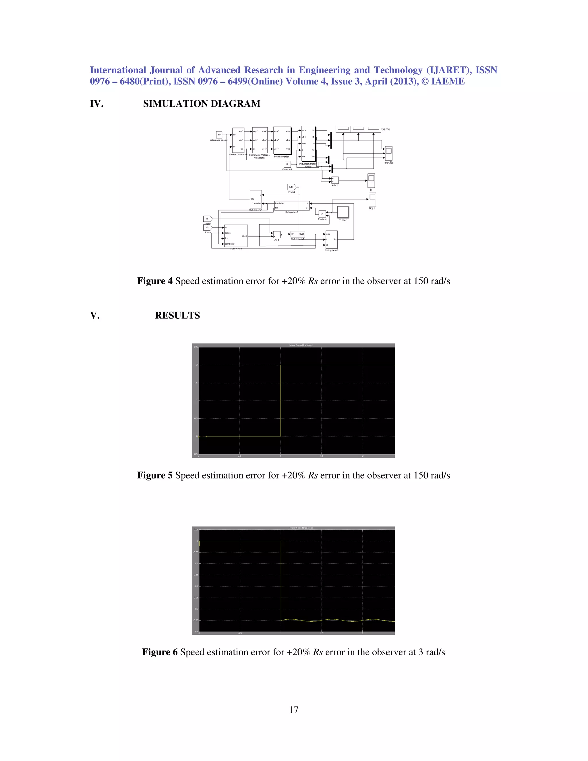
This document summarizes a research paper on speed estimation error of sensorless induction motor drives using soft computing techniques. It presents parallel speed and stator resistance identification schemes to overcome resistance variation problems. A sliding mode current observer is combined with Popov's hyperstability theory to obtain estimation algorithms. Activation of an online stator resistance adaptation mechanism compensates initial resistance estimation errors and eliminates initial speed errors. Simulation results show that speed estimation error decreases with decreasing reference speed and when using fuzzy logic control compared to PI control. The paper concludes soft computing techniques can decrease speed estimation error in sensorless induction motor drives.