
Downloaded 21 times
![International Journal of Technical Research and Applications e-ISSN: 2320-8163, www.ijtra.com Volume 2, Issue 3 (May-June 2014), PP. 163-168 164 | P a g e algorithm is selected, the whole step by step processing can be avoided by downloading the algorithm into a processor. This can be inserted into the system for using a particular technique. The embedded signal processing systems used for radar data processing contains many of these processor cards, which varies according to the processing steps needed to extract the required data. In a radar system, where, real time operation is important, such an embedded processor is really useful. This will increase the computational complexity as well as increase the accuracy. II. STAP BACKGROUND STAP stands for Space Time Adaptive Processing which is a signal processing technique most commonly used in radar systems. It involves adaptive array processing algorithms to aid in target detection. Radar signal processing benefits from STAP in areas where interference is a problem (ground clutter, jamming).A space-time snapshot was defined to be the slice of the data cube corresponding to a single range gate as shown in Figure 1. This data may contain a target component as well as undesired components due to noise, jamming, and clutter. The target signal is modelled as a random amplitude times a space-time steering vector that has the target's angle and Doppler. The undesired signal components are modelled as random processes and expressions for their covariance matrices are derived. Fig 1: Radar CPI Data cube A Problem Description The radar antenna is a uniformly spaced linear array antenna consisting of N elements. Radar returns are collected in a coherent processing interval (CPI), which is referred to as the 3-D radar data cube shown in Figure. 1, where L denotes the number of samples collected to cover the range interval. The data is then processed at one range of interest, which corresponds to a slice of the CPI data cube. This slice is an M × N matrix which consists of N × spatial snapshots for M pulses at the range of interest. It is convenient to stack the matrix column-wise to form the J × ,J MN vector ri , termed a space-time snapshot [1],[2]. The function of radar is to ascertain whether targets are present in the data. The vector ru is used to estimate the interference covariance matrix Ru which consists of the summation of clutter matrix Rc, jammer matrix Rj, and thermal noise matrix Rn.Thus, the J × J covariance matrix Ru of the undesired clutter-plus-jammer-plus-noise component can be modelled as Ru =E{ruru H } = Rc + Rj + Rn (1) Where H represents Hermitian transpose, Rc where H represents Hermitian transpose, Rc = E{rcrc H },Rj =E{rjrj H } and Rn =E{rnrn H } denote clutter, jamming and noise covariance matrix respectively. In practice, the interference-plus-noise covariance matrix Ru is typically unknown. The common approach is to estimate it from the secondary data set which does not contain the signal of interest (r = ru). In this context, we can refer the interference-plus-noise covariance matrix Ru as R. In practice, since R is unknown, the processor substitutes an estimation of R for to arrive at the adaptive weight ω. It is most common to compute the covariance matrix estimate as = . This approach is known as sample matrix inversion (SMI). Another conventional method for suppressing clutter is the DPCA method. The displaced phase centre antenna (DPCA) algorithm is often considered to be the first STAP algorithm. This algorithm uses the shifted aperture to compensate for the platform motion so that the clutter return does not change from pulse to pulse. Thus, this algorithm can remove the clutter via a simple subtraction of two consecutive pulses. B Literature Survey Research has focused on the use of space-time adaptive processing (STAP) fix interference cancellation in airborne radar systems since 1970’s. The theory of adaptive radar [1] have been explained by L. E. Brennan and L. S. Reed. After that some conventional methods were developed to estimate the adaptive weights for filtering out the clutters [2, 3]. Then methods based on Eigen values and Eigen vectors were used to estimate the weight vectors [4, 5, 6, 7] by scientists A. M. Haimovich and Y. Bar-Ness. This method is based on the fact that the highest power is concentrated on the Eigen values of a matrix. These](https://image.slidesharecdn.com/ijtra140399-151007110839-lva1-app6891/75/SPACE-TIME-ADAPTIVE-PROCESSING-FOR-CLUTTER-SUPPRESSION-IN-RADAR-USING-SUBSPACE-BASED-TECHNIQUE-2-2048.jpg)
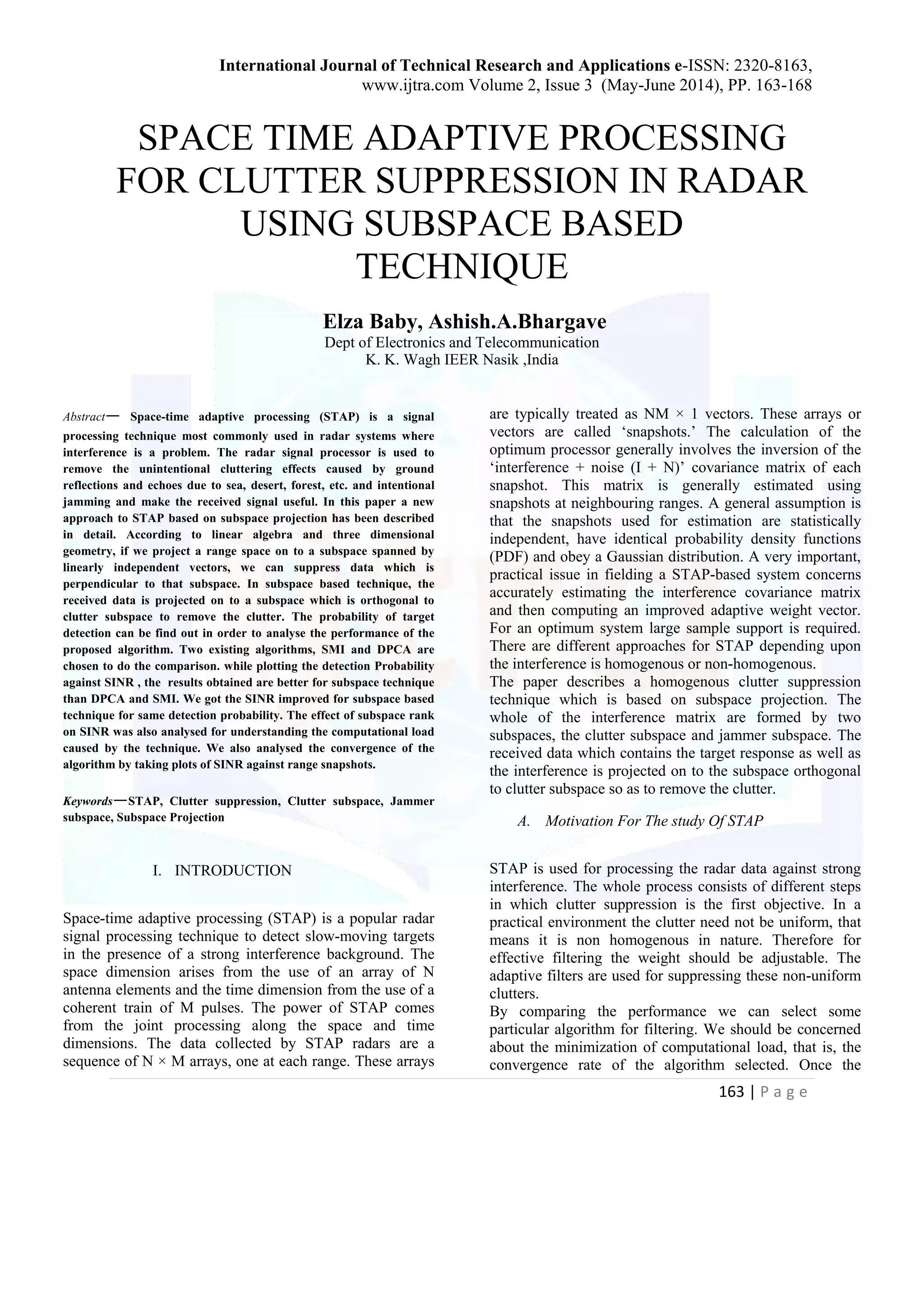
![International Journal of Technical Research and Applications e-ISSN: 2320-8163, www.ijtra.com Volume 2, Issue 3 (May-June 2014), PP. 163-168 165 | P a g e methods were simple to perform but the accuracy was not always good due to insufficient data for estimating the interference matrix. Some STAP approaches used circular arrays [8,9] of antennas for the purpose. For non- homogenous clutter suppression different techniques were found out based non statistical estimation of the weight vector [10, 11]. Many scientists like T. K. Sarkar, S. Park, J. Koh, and R. A. Schneible worked on this area and contributed their ideas. Studies based on Subspace approach for clutter suppression [12, 13, 14] started in 1990’s and they are found to be easier to implement. Recent studies are based on improving the performance of the technique by reducing the rank of the subspace. III. SUBSPACE APPROACH IN STAP In this section we describe a technique based on subspace projection which is used to suppress the homogenous clutter. This uses an observation that the clutter returns are range dependant, because it exists at all ranges of interest, to obtain an improved estimate of the covariance matrix R(u) from measured data x(r). The subspace technique is based on the theory of subspace projection in three dimensional geometry. Consider a point P(x, y, z) in XYZ space. If this point is projected on to an orthogonal plane, say XY plane the z co-ordinate will be eliminated. This means that this is another form of representing the point P(x, y, z) using different basis vectors. Same is the case with received data, which is a three dimensional matrix which contains clutters, jammers, and target data. The clutter subspace and jammer subspace are orthogonal to each other because they are independent vectors and satisfy the properties of orthogonality. Therefore if the received data is firstly projected on to a subspace orthogonal to clutter subspace that is jammer subspace then the clutters can be eliminated. And the jammer can be easily nulled out from the resulting signal to make it a useful signal. The whole algorithm is based on the matrix operation called projection, which is actually representation of same data using different basis vectors. Here we need to know more about clutter and jammer subspaces to understand the process well. A. Clutter and Jammer Subspaces The clutter subspace Sc can be described as the subspace spanned by the array response vectors with Doppler combinations corresponding to clutter patches. The remaining vectors U span s subspace orthogonal to Sc, which we denote as Sc┴. For notational convenience both Sc and Sc┴ are assumed to matrices with orthonormal columns. R{Sc(r)}≈R{[Vst(ϕ,f1;r),.....Vst(ϕ,fN;r)]} (2) Where R{A} denotes the range space of matrix A. For a jammer component rj, the vector exists in a relatively low dimensional subspace. This subspace can be found out by singular value decomposition of Rj. The jammer subspace Sj is spanned by the array response vectors corresponding to the jammer azimuth and all possible Doppler frequencies. R{Sj(r)}≈ R{[Vst(ϕj,f1;r),.....Vst(ϕj,fN;r)]} (3) Projecting the data on to the columns of Sc ┴, we can remove the clutter component because (Sc┴)H r(r)=(Sc┴)H rc(r)+ (Sc┴)H rj(r)+(Sc┴)H rn(r) (4) ≈ (Sc┴)H rj(r) + (Sc┴)H rn(r) The degree to which the clutter can be removed depends upon the quality of the subspace chosen. By knowing the array response and the platform position relative to ground, we can compute Sc┴ without requiring any measured data. Thus the process of clutter removal can be accomplished without the potentially estimation of the covariance matrix .however to complete the space time processing we have to compute the jammer covariance matrix. In practice, the accurate estimation of the clutter subspace requires a more sophisticated and detailed local earth model, rather than relatively simple model chosen here. The sensitivity to the clutter model can be reduced by increasing the dimension of the clutter subspace or equivalently reducing the dimension of Sc┴. Estimating the jammer signal from receive only data does have some drawbacks that is they reduce the time for active radar operation and there is always a chance that the jammer may change after it was measured. IV. SIMULATIONS AND ANALYSIS For simulations we use the Monte Carlo simulations for randomly generating the signal and noise based on statistic. The 8 element ULA is defined and element](https://image.slidesharecdn.com/ijtra140399-151007110839-lva1-app6891/75/SPACE-TIME-ADAPTIVE-PROCESSING-FOR-CLUTTER-SUPPRESSION-IN-RADAR-USING-SUBSPACE-BASED-TECHNIQUE-3-2048.jpg)
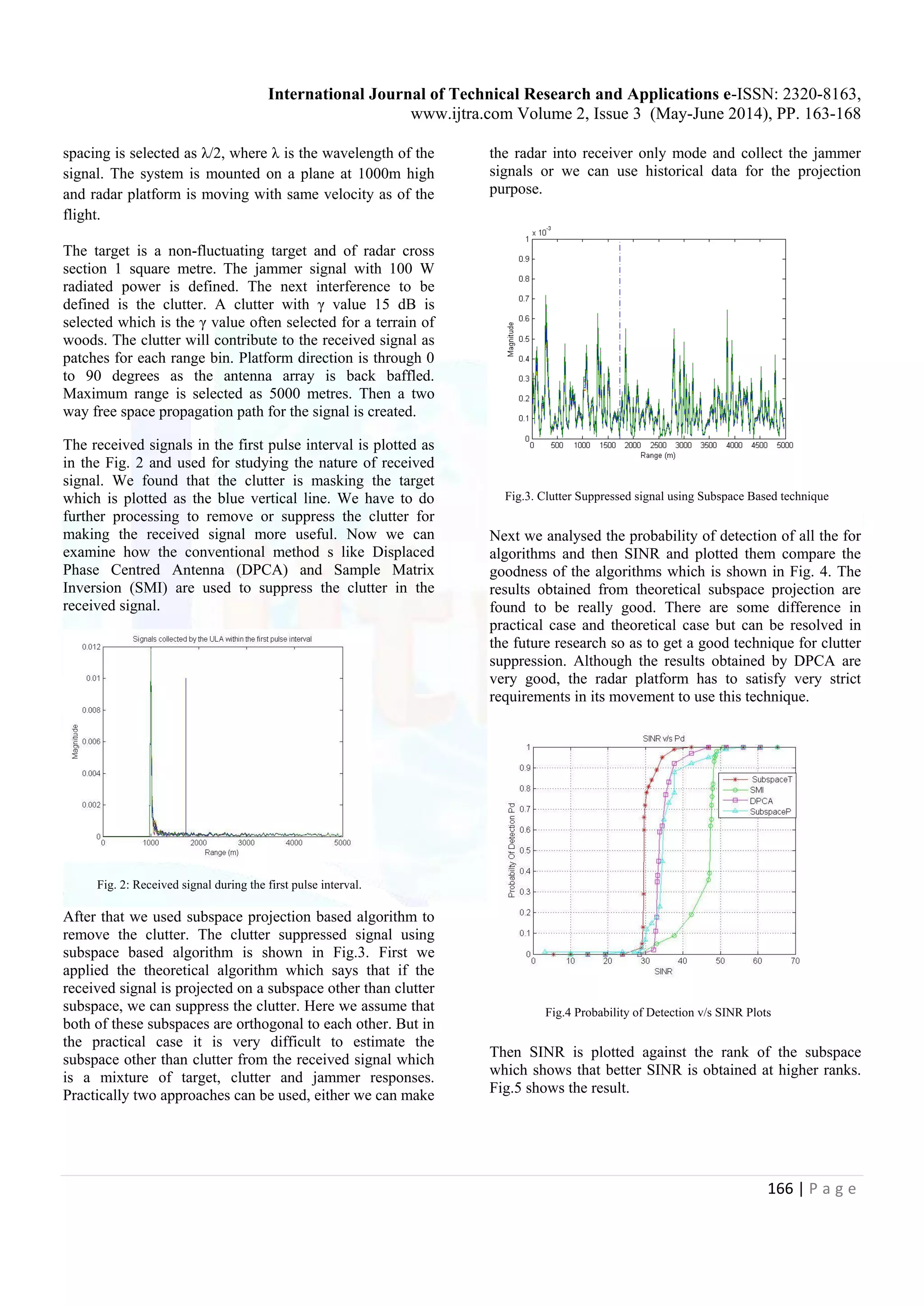
![International Journal of Technical Research and Applications e-ISSN: 2320-8163, www.ijtra.com Volume 2, Issue 3 (May-June 2014), PP. 163-168 167 | P a g e Fig. 5 SINR v/s Rank of the subspace The SINR is also plotted against the no: of range gates and found that higher ranges results are good. The result is shown in Fig.6. Fig. 6 SINR v/s Range Snapshots V. CONCLUSION The ground moving target surveillance is a very important application of radars as always. But usually airborne radars used for the purpose are faced with objections caused by the interference. STAP has been a best option for suppressing the clutters and make targets detectable. The subspace based technique for clutter suppression is based on matrix operations and are easy to apply. The subspace can be chosen by measuring the orthogonality between the received signal space and the subspace in which the data is to be projected. This method consumes less time to perform the operation and does not have any hardware issues like DPCA algorithm. The probability of detection against SINR is found to be the best for Subspace projection based technique. The future works can find a more effective practically possible subspace and eliminate the parity between both cases. If the rank of the subspace we can improve the performance of the algorithm, but this will increase the computational load. So we always try to keep a compromise between rank and Signal strength. ACKNOWLEDGMENT I express my heart filled gratitude to Prof. Dinesh M Chandwadkar, HOD, Department of Electronics and Communication, KKWIEER for giving me the opportunity to carry out this project. I profusely thank Prof. Dr. Ashish.A.Bhargave, my guide and mentor who helped me in every step of the project, patiently clearing out my incessant doubts. His technical competence is far beyond imagination. Both as a person and guide he has lead me into a realm of professionalism. I would also like to thank my teachers and friends who have helped me to do the work successfully. REFERENCES [1] L. E. Brennan and L. S. Reed, “Theory of adaptive radar”, Aerospaceand Electronic Systems, IEEE Transactions on, vol. AES-9, no. 2, pp.237–252, 1973. [2] J. Ward, “Space-Time Adaptive Processing for Airborne Radar”, Technical Report 1015, MIT Lincoln Laboratory, Lexington, MA, USA, 1994 (available: http://handle.dtic.mil/100.2/ADA293032) [3] D. Rabideau and A. Steinhardt, “Improved Adaptive Clutter Cancellation through Data-Adaptive Training”, IEEE Transactions on Aerospace and Electronic Systems, vol. 35, no. 3 (1999), pp. 879-891 [4] A. M. Haimovich and Y. Bar-Ness, “An Eigen analysis interference canceller”, Signal Processing, IEEE Transactions on, vol. 39, no. 1,pp. 76–84, 1991. [5] A. Haimovich, “The Eigen canceller: adaptive radar by Eigen analysis methods”, Aerospace and Electronic Systems, IEEE Transactions on,vol. 32, no. 2, pp. 532–542, 1996. [6] A. M. Haimovich and M. Berin, “Eigen analysis-based space- time adaptive radar: performance analysis”, Aerospace and Electronic Systems,IEEE Transactions on, vol. 33, no. 4, pp. 1170–1179, 1997. [7] BARBAROSSA,S., and FARINA,A,:”Space time frequency processing of synthetic aperture radar signals”,IEEE TRANS. Aerosp.Electron.syst,1994,30,pp 341-358 [8] Zatman, M “Circular array STAP”.IEEE Transactions on Aerospace and Electronic Systems,36, 2 (Apr. 2000), 510-517. [9] Tapan K. Sarkar and RavirajAdve “Space-Time Adaptive Processing Using Circular Arrays” IEEE Antennas and Propagation Magazine, Vol. 43, No. 1, February 2001 pp.138 - 143 [10] T. K. Sarkar, S. Park, J. Koh, and R. A. Schneible, “A deterministic least square approach to adaptive antennas,” Digital Signal Processing— Rev.J., vol. 6, pp. 185–194, 1996.](https://image.slidesharecdn.com/ijtra140399-151007110839-lva1-app6891/75/SPACE-TIME-ADAPTIVE-PROCESSING-FOR-CLUTTER-SUPPRESSION-IN-RADAR-USING-SUBSPACE-BASED-TECHNIQUE-5-2048.jpg)
![International Journal of Technical Research and Applications e-ISSN: 2320-8163, www.ijtra.com Volume 2, Issue 3 (May-June 2014), PP. 163-168 168 | P a g e [11] T. K. Sarkar, H. Waiig, S. Park, R. Adve, J. Koh, Y. Zhang, M.C. Wicks, and R. D. Brown, “A Deterministic Least Squares Approach to Space-Time Adaptive Processing (STAP),” IEEE Transactions on Antennas am1 Propagation, Dec 2000 [12] B. Friedlander, "A Subspace Method for Space Time Adaptive Processing,"IEEE Trans. Sig. Proc. pp. 74-82, Jan. 2005. [13] J. S. Goldstein and I. S. Reed, “Subspace selection for partially adaptive sensor array processing”, Aerospace and Electronic Systems, IEEE Transactions on, vol. 33, no. 2, pp. 539–544, 1997. [14] Samira Dib1 , Mourad Barkat, Jean-Marie Nicolas, Morad Grimes “A Reduced Rank STAP and Staggered PRF for Multiple Target Situations” International Journal on New Computer Architectures and Their Applications (IJNCAA) 2(1): 52-69 The Society of Digital Information and Wireless Communications, 2012 (ISSN: 2220-9085](https://image.slidesharecdn.com/ijtra140399-151007110839-lva1-app6891/75/SPACE-TIME-ADAPTIVE-PROCESSING-FOR-CLUTTER-SUPPRESSION-IN-RADAR-USING-SUBSPACE-BASED-TECHNIQUE-6-2048.jpg)
The document presents a study on space-time adaptive processing (STAP) techniques for clutter suppression in radar systems using a subspace-based method. It discusses the methodology of projecting received radar data onto a subspace that is orthogonal to the clutter subspace to improve target detection probability and reduce interference from ground reflections and jamming. The results indicate that the proposed subspace technique outperforms existing algorithms like sample matrix inversion (SMI) and displaced phase center antenna (DPCA) in terms of signal-to-interference-plus-noise ratio (SINR) while maintaining a balance between computational load and performance.