Asian Journal of Applied Science and Technology (AJAST) Volume 1, Issue 1, Pages 126-130, February 2017 © 2017 AJAST All rights reserved. www.ajast.net Page | 126 Reduced Complexity Maximum Likelihood Decoding Algorithm for LDPC Code Correction Technique A.V.Manjupriya1 and G.Yuvaraj2 1 PG Student, Department of ECE, Vivekanandha College of Engineering for Women, Tiruchengode, Tamilnadu, India. 2 Assistant Professor, Department of ECE, Vivekanandha College of Engineering for Women, Tiruchengode, Tamilnadu, India. Article Received: 13 February 2017 Article Accepted: 22 February 2017 Article Published: 27 February 2017 1. INTRODUCTION NONBINARY low-density parity-check (NB-LDPC) codes are a real kind of linear block codes defined over Galois fields (GFs) GF (q = 2p) with p >1. NB-LDPC codes have lot of advantages over its binary counterparts, including better error correction performance for short/medium code word length, higher burst error correction capability, and improved performance in the error-floor region. The main disadvantage of NB-LDPC codes is the high complexity of the decoding algorithms and the derived hardware architectures, which limit their application in real scenarios where high throughput and reduced silicon area are important requirements. The main drawbacks of T-EMS, T-MM, and OMO-TMM are: 1) the high number of exchanged messages between the CN and the VN (q × dc reliabilities), which impacts in the wiring congestion, limiting the maximum throughput achievable and 2) the high amount of storage elements required in the hardware implementations of these algorithms, which supposes the major part of the decoder’s area. This reduction in messages introduces a performance loss in the coding gain that can be controlled by means of the parameter L. NB-LDPC codes are decoded applying iterative algorithms where messages that represent reliability values are passed from VN to CN and vice versa. Extended min-sum (EMS) and min–max algorithms were proposed with the aim of reducing the complexity offered by the solutions based on QPSA. In these algorithms, the CN equations are simplified by making approximations to involve only additions and comparisons in their parity-check equations. Since both the algorithms make use of forward–backward (FB) metrics in the CN processor, the maximum throughput is bounded due to serial computations. The number of exchanged messages between CN and variable node (VN) for both the algorithms is nm × dc, where nm is a fraction of q total reliabilities, nm _ q, and dc the CN degree. Therefore, the number of messages between the nodes is lower than the previous solutions from the literature. Improvements based on QSPA, such as Fast Fourier Transform-SPA, log-SPA, and max-log-SPA, reduce the computational load of the parity-check equations without introducing any performance loss. The recently proposed trellis max-log-QPSA algorithm improves considerably both the area and the decoding throughput compared with the previous solutions based on QPSA, making use of a path construction scheme to generate the output message in the check-node (CN) processor. These solutions offer the highest coding gain for high-rate NB-LDPC codes, but at the same time, they include costly processing that limits their application in real communication and storage systems. 2. EXISTING SYSTEM 2.1 Introduction The analysis of the algorithm then views on the work required for the merging process, because it is the merge work needed for a given subdivision scheme that ultimately determines the growth of complexity. In this we introduce a recursive approach to the construction of codes which generalizes the product code construction and suggests that the design of algorithms for encoding and decoding is amenable to the first techniques of complexity theory. Long codes are built from a bipartite graph and one or more sub codes; a new code is defined explicitly by its decomposition into shorter sub codes. These sub codes are then used by the decoder as centres of local partial computations that, when performed iteratively, correct the errors. The decoding algorithms we propose generalize and unify the decoding schemes originally presented the product codes and those of low-density parity-check code. Furthermore, the proper choice of the transmission order for the bits can guarantee better performance against burst errors or a mixture of burst and random errors. ABSTRACT In this paper, low linear architectures for analyzing the first two maximum or minimum values are of paramount importance in several uses, including iterative decoders. The min-sum giving out step is to that it produces only two diverse output magnitude values irrespective of the number of incoming bit-to check communication. These new micro-architecture structures would utilize the minimum number of comparators by exploiting the concept of survivors in the search. These would result in reduced number of comparisons and consequently reduced energy use. Multipliers are complex units and play an important role in finding the overall area, speed and power consumption of digital designs. By using the multiplier we can minimize the parameters like latency, complexity and power consumption. The decoding algorithms we propose generalize and unify the decoding schemes originally presented the product codes and those of low-density parity-check codes. Keywords: Check–node (CN) processing, high-rate, high-speed, layered schedule, message compression, NB-LDPC, trellis min-max (T-MM) and VLSI design.
Asian Journal of Applied Science and Technology (AJAST) Volume 1, Issue 1, Pages 126-130, February 2017 © 2017 AJAST All rights reserved. www.ajast.net Page | 127 2.2 Project Description NON-BINARY low-density parity-check (NB-LDPC) codes are a promising kind of linear block codes defined over Galois fields (GFs) GF(q = 2p) with p >1. NB-LDPC codes have numerous advantages over its binary counterparts, including better error correction performance for short/medium code word length, higher burst error correction capability, and improved performance in the error-floor region. 2.3 T-MM Decoding Algorithm with Compressed Messages A sparse parity-check matrix H defines an NB-LDPC code, where each nonzero element h m ,n belongs to a GFs GF(q = 2p). Another common way to characterize the NB-LDPC codes is by means of a Tanner graph, where two kinds of nodes are differentiated representing all N columns (VNs) and M rows (CNs) of H. N(m) denotes the set of VNs connected to a CN m and M(n) denotes the set of CNs connected to a VN n; therefore, the cardinality of the sets corresponds to dc and dv. 2.4 T-MM Algorithm with Reduced Set of Messages In this section, we introduce a novel method to reduce the number of messages exchanged between the CN and the VN compared with the proposal from [11]. First, we define the reduced set of compressed messages that are sent from CN to VN and an approximation to obtain the rest of values in the VN. Second, the performance of the method is analyzed. Third, a technique to generate the most reliable values of the set I (a) without building a complete trellis structure is presented 2.5 Reduction of the CN-to-VN Message The sets I (a) and P(a) are required to generate the messages Rm,n(a) at the VN processor, as shown in (3). Reducing the cardinality of I (a), the one of P(a) is also reduced. Our proposal is to keep the L most reliable values of I (a) and the corresponding ones of P(a) and E(a), where L < (q −1).Defining the complementary set a__ ∈a a_, we propose to set E∗(a__) = m1(a__). Therefore, the cardinality of the set E∗(a) is kept in q −1. Table I includes the number of bits of each one of the sets exchanged from CN-to-VN processors compared with the proposal from [11], where w is the number of bits used to quantize the reliabilities. Fig.1. Mean value of each reliability 2.6 Conclusion The main drawbacks of T-EMS, T-MM, and OMO-TMM are: 1) the high number of exchanged messages between the CN and the VN (q × dc reliabilities), which impacts in the wiring congestion, limiting the maximum throughput achievable and 2) the high amount of storage elements required in the hardware implementations of these algorithms, which supposes the major part of the decoder’s area. To overcome the drawbacks of T-EMS and T-MM, the proposal in [11] introduces a technique of message compression that reduces the wiring congestion between the CN and the VN and the storage elements used in the derived architectures. The messages at the output of the CN are reduced to four elementary sets that include the intrinsic and extrinsic information, the path coordinates, and the hard-decision symbols. 3. PROPOSED SYSTEM The block diagram for the proposed CN is detailed in Fig. 2a. The CN input messages are Q m, n, which come from the VN processor and the tentative hard-decision symbols z. Both the input messages are used to compute the normal to- delta-domain transformation (N →_ block in Fig. 2b). DC transformation networks are needed in the CN, each one requires q×log(q) w-bit MUX following the approach proposed in [19], where w is the number of bits for the data path. Z is also used to obtain the syndrome β adding all dc tentative hard-decision symbols. This operation requires w × (dc − 1) XOR gates. Fig.2a. Proposed check node Block Diagram β is used to generate the new hard decision symbols z∗, which are sent to the VN to generate the R∗m,n messages using (4). Z ∗ symbols are generated using GF(q) adders that require dc × w XOR gates to implement them. 3.1 Decoding As with other codes, optimally decoding an LDPC code on the binary symmetric channel is the NP-complete problem, although techniques based on iterative belief propagation used in practice lead to good approximations. In contrast, belief propagation on the binary erasure channel is usually simple where it consists of iterative constraint satisfaction.
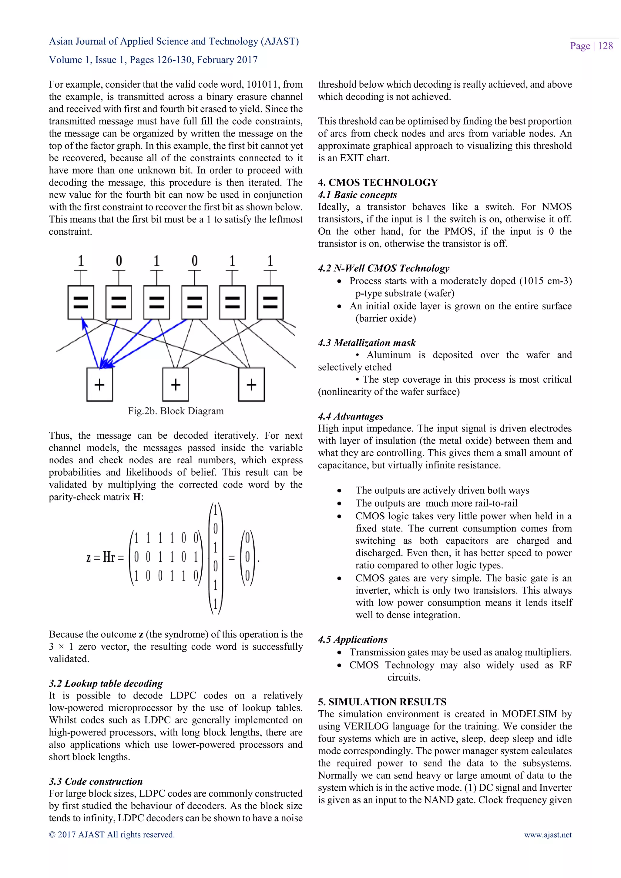
Asian Journal of Applied Science and Technology (AJAST) Volume 1, Issue 1, Pages 126-130, February 2017 © 2017 AJAST All rights reserved. www.ajast.net Page | 128 For example, consider that the valid code word, 101011, from the example, is transmitted across a binary erasure channel and received with first and fourth bit erased to yield. Since the transmitted message must have full fill the code constraints, the message can be organized by written the message on the top of the factor graph. In this example, the first bit cannot yet be recovered, because all of the constraints connected to it have more than one unknown bit. In order to proceed with decoding the message, this procedure is then iterated. The new value for the fourth bit can now be used in conjunction with the first constraint to recover the first bit as shown below. This means that the first bit must be a 1 to satisfy the leftmost constraint. Fig.2b. Block Diagram Thus, the message can be decoded iteratively. For next channel models, the messages passed inside the variable nodes and check nodes are real numbers, which express probabilities and likelihoods of belief. This result can be validated by multiplying the corrected code word by the parity-check matrix H: Because the outcome z (the syndrome) of this operation is the 3 × 1 zero vector, the resulting code word is successfully validated. 3.2 Lookup table decoding It is possible to decode LDPC codes on a relatively low-powered microprocessor by the use of lookup tables. Whilst codes such as LDPC are generally implemented on high-powered processors, with long block lengths, there are also applications which use lower-powered processors and short block lengths. 3.3 Code construction For large block sizes, LDPC codes are commonly constructed by first studied the behaviour of decoders. As the block size tends to infinity, LDPC decoders can be shown to have a noise threshold below which decoding is really achieved, and above which decoding is not achieved. This threshold can be optimised by finding the best proportion of arcs from check nodes and arcs from variable nodes. An approximate graphical approach to visualizing this threshold is an EXIT chart. 4. CMOS TECHNOLOGY 4.1 Basic concepts Ideally, a transistor behaves like a switch. For NMOS transistors, if the input is 1 the switch is on, otherwise it off. On the other hand, for the PMOS, if the input is 0 the transistor is on, otherwise the transistor is off. 4.2 N-Well CMOS Technology  Process starts with a moderately doped (1015 cm-3) p-type substrate (wafer)  An initial oxide layer is grown on the entire surface (barrier oxide) 4.3 Metallization mask • Aluminum is deposited over the wafer and selectively etched • The step coverage in this process is most critical (nonlinearity of the wafer surface) 4.4 Advantages High input impedance. The input signal is driven electrodes with layer of insulation (the metal oxide) between them and what they are controlling. This gives them a small amount of capacitance, but virtually infinite resistance.  The outputs are actively driven both ways  The outputs are much more rail-to-rail  CMOS logic takes very little power when held in a fixed state. The current consumption comes from switching as both capacitors are charged and discharged. Even then, it has better speed to power ratio compared to other logic types.  CMOS gates are very simple. The basic gate is an inverter, which is only two transistors. This always with low power consumption means it lends itself well to dense integration. 4.5 Applications  Transmission gates may be used as analog multipliers.  CMOS Technology may also widely used as RF circuits. 5. SIMULATION RESULTS The simulation environment is created in MODELSIM by using VERILOG language for the training. We consider the four systems which are in active, sleep, deep sleep and idle mode correspondingly. The power manager system calculates the required power to send the data to the subsystems. Normally we can send heavy or large amount of data to the system which is in the active mode. (1) DC signal and Inverter is given as an input to the NAND gate. Clock frequency given
Asian Journal of Applied Science and Technology (AJAST) Volume 1, Issue 1, Pages 126-130, February 2017 © 2017 AJAST All rights reserved. www.ajast.net Page | 129 as NAND gate for simulation output. (2) Q BAR, QBAR1 is the output signal. Fig.3. Digital schematic for circuit to extract the jth minimum value Fig.4. Design Layout for the output waveform Fig.5. Simulation result for voltage versus time. Fig.6. Simulation result for voltage and current Fig.7. Simulation Result for voltage versus voltage Fig.8. Simulation result for frequency versus time
Asian Journal of Applied Science and Technology (AJAST) Volume 1, Issue 1, Pages 126-130, February 2017 © 2017 AJAST All rights reserved. www.ajast.net Page | 130 Fig.9. Simulation result for eye diagram 6. CONCLUSION AND FUTURE ENHANCEMENT The low complexity design is prominent requirement of iterative decoders. We have tried to propose a design that fulfills the obligation with the completion of the sum min worker using better architecture. The difficulty is reduced as the number of register and memory utilization decreases. NB-LDPC codes are designed using CMOS Technology. It concludes the T-MM algorithm to reduce the complexity of CN architecture. Hence the power consumption is reduced. In future, LDPC codes can be used for reducing the power consumption. Thus, the post synthesis throughput of the other works is reduced in the same percentage. REFERENCES [1] Cai.F and Zhang.X, “Relaxed min-max decoder architectures for nonbinary low-density parity-check codes,” IEEE Trans. Very Large Scale Integr. (VLSI) Syst., vol. 21, no. 11, pp. 2010–2023, Nov. 2013. [2] Jesus O. Lacruz, Francisco García-Herrero, María Jose Canet, and Javier Valls, “Reduced-Complexity Non-binary LDPC Decoder for High-Order Galois Fields Based on Trellis Min–Max Algorithm”, IEEE Transactions on very large scale integration (VLSI) Systems, 2016. [3] Lacruz. J.O, García-Herrero.F, Declercq.D, and Valls.J, “Simplified trellis min–max decoder architecture for nonbinary low-density parity check codes,” IEEE Trans. Very Large Scale Integr. (VLSI) Syst., vol. 23, no. 9, pp. 1783–1792, Sep. 2015. [4] Li.E, Declercq.D, and Gunnam.K, “Trellis-based extended min-sum algorithm for non-binary LDPC codes and its hardware structure,” IEEE Trans. Commun. vol. 61, no. 7, pp. 2600–2611, Jul. 2013. [5] Lin.J, Sha.J, Wang.Z, and Li.L, “Efficient decoder design for nonbinary quasicyclic LDPC codes,” IEEE Trans. Circuits Syst. I, Reg.Papers, vol. 57, no. 5, pp. 1071–1082, May 2010. [6] Mansour.M.M and Shanbhag.N.R, “High-throughput LDPC decoders,” IEEE Trans. Very Large Scale Integr. (VLSI) Syst., vol. 11, no. 6, pp. 976–996, Dec. 2003. [7] Savin.V, “Min-max decoding for non-binary LDPC codes,” in Proc. IEEE Int. Symp. Inf. Theory, Jul. 2008, pp. 960–964. [8] Ueng.Y.-L, Liao.K.-H, Chou.H.-C, and Yang.C.-J., “A high-throughput trellis based layered decoding architecture for non-binary LDPC codes using max-log-QSPA,” IEEE Trans. Signal Process., vol. 61, no. 11, pp. 2940–2951, Jun. 2013. [9] Wymeersch.H, Steendam.H, and Moeneclaey.M, “Log-domain decoding of LDPC codes over GF(q),” in Proc. IEEE Int. Conf. Commun., vol. 2. Jun. 2004, pp. 772–776. [10] Zhou.B, Kang.J, Song.S, Lin.S, Abdel-Ghaffar.K, and Xu.M, “Construction of non-binary quasi-cyclic LDPC codes by arrays and array dispersions,” IEEE Trans. Commun., vol. 57, no. 6, pp. 1652–1662, Jun. 2009.

Reduced Complexity Maximum Likelihood Decoding Algorithm for LDPC Code Correction Technique

  • 1.
    Asian Journal ofApplied Science and Technology (AJAST) Volume 1, Issue 1, Pages 126-130, February 2017 © 2017 AJAST All rights reserved. www.ajast.net Page | 126 Reduced Complexity Maximum Likelihood Decoding Algorithm for LDPC Code Correction Technique A.V.Manjupriya1 and G.Yuvaraj2 1 PG Student, Department of ECE, Vivekanandha College of Engineering for Women, Tiruchengode, Tamilnadu, India. 2 Assistant Professor, Department of ECE, Vivekanandha College of Engineering for Women, Tiruchengode, Tamilnadu, India. Article Received: 13 February 2017 Article Accepted: 22 February 2017 Article Published: 27 February 2017 1. INTRODUCTION NONBINARY low-density parity-check (NB-LDPC) codes are a real kind of linear block codes defined over Galois fields (GFs) GF (q = 2p) with p >1. NB-LDPC codes have lot of advantages over its binary counterparts, including better error correction performance for short/medium code word length, higher burst error correction capability, and improved performance in the error-floor region. The main disadvantage of NB-LDPC codes is the high complexity of the decoding algorithms and the derived hardware architectures, which limit their application in real scenarios where high throughput and reduced silicon area are important requirements. The main drawbacks of T-EMS, T-MM, and OMO-TMM are: 1) the high number of exchanged messages between the CN and the VN (q × dc reliabilities), which impacts in the wiring congestion, limiting the maximum throughput achievable and 2) the high amount of storage elements required in the hardware implementations of these algorithms, which supposes the major part of the decoder’s area. This reduction in messages introduces a performance loss in the coding gain that can be controlled by means of the parameter L. NB-LDPC codes are decoded applying iterative algorithms where messages that represent reliability values are passed from VN to CN and vice versa. Extended min-sum (EMS) and min–max algorithms were proposed with the aim of reducing the complexity offered by the solutions based on QPSA. In these algorithms, the CN equations are simplified by making approximations to involve only additions and comparisons in their parity-check equations. Since both the algorithms make use of forward–backward (FB) metrics in the CN processor, the maximum throughput is bounded due to serial computations. The number of exchanged messages between CN and variable node (VN) for both the algorithms is nm × dc, where nm is a fraction of q total reliabilities, nm _ q, and dc the CN degree. Therefore, the number of messages between the nodes is lower than the previous solutions from the literature. Improvements based on QSPA, such as Fast Fourier Transform-SPA, log-SPA, and max-log-SPA, reduce the computational load of the parity-check equations without introducing any performance loss. The recently proposed trellis max-log-QPSA algorithm improves considerably both the area and the decoding throughput compared with the previous solutions based on QPSA, making use of a path construction scheme to generate the output message in the check-node (CN) processor. These solutions offer the highest coding gain for high-rate NB-LDPC codes, but at the same time, they include costly processing that limits their application in real communication and storage systems. 2. EXISTING SYSTEM 2.1 Introduction The analysis of the algorithm then views on the work required for the merging process, because it is the merge work needed for a given subdivision scheme that ultimately determines the growth of complexity. In this we introduce a recursive approach to the construction of codes which generalizes the product code construction and suggests that the design of algorithms for encoding and decoding is amenable to the first techniques of complexity theory. Long codes are built from a bipartite graph and one or more sub codes; a new code is defined explicitly by its decomposition into shorter sub codes. These sub codes are then used by the decoder as centres of local partial computations that, when performed iteratively, correct the errors. The decoding algorithms we propose generalize and unify the decoding schemes originally presented the product codes and those of low-density parity-check code. Furthermore, the proper choice of the transmission order for the bits can guarantee better performance against burst errors or a mixture of burst and random errors. ABSTRACT In this paper, low linear architectures for analyzing the first two maximum or minimum values are of paramount importance in several uses, including iterative decoders. The min-sum giving out step is to that it produces only two diverse output magnitude values irrespective of the number of incoming bit-to check communication. These new micro-architecture structures would utilize the minimum number of comparators by exploiting the concept of survivors in the search. These would result in reduced number of comparisons and consequently reduced energy use. Multipliers are complex units and play an important role in finding the overall area, speed and power consumption of digital designs. By using the multiplier we can minimize the parameters like latency, complexity and power consumption. The decoding algorithms we propose generalize and unify the decoding schemes originally presented the product codes and those of low-density parity-check codes. Keywords: Check–node (CN) processing, high-rate, high-speed, layered schedule, message compression, NB-LDPC, trellis min-max (T-MM) and VLSI design.
  • 2.
    Asian Journal ofApplied Science and Technology (AJAST) Volume 1, Issue 1, Pages 126-130, February 2017 © 2017 AJAST All rights reserved. www.ajast.net Page | 127 2.2 Project Description NON-BINARY low-density parity-check (NB-LDPC) codes are a promising kind of linear block codes defined over Galois fields (GFs) GF(q = 2p) with p >1. NB-LDPC codes have numerous advantages over its binary counterparts, including better error correction performance for short/medium code word length, higher burst error correction capability, and improved performance in the error-floor region. 2.3 T-MM Decoding Algorithm with Compressed Messages A sparse parity-check matrix H defines an NB-LDPC code, where each nonzero element h m ,n belongs to a GFs GF(q = 2p). Another common way to characterize the NB-LDPC codes is by means of a Tanner graph, where two kinds of nodes are differentiated representing all N columns (VNs) and M rows (CNs) of H. N(m) denotes the set of VNs connected to a CN m and M(n) denotes the set of CNs connected to a VN n; therefore, the cardinality of the sets corresponds to dc and dv. 2.4 T-MM Algorithm with Reduced Set of Messages In this section, we introduce a novel method to reduce the number of messages exchanged between the CN and the VN compared with the proposal from [11]. First, we define the reduced set of compressed messages that are sent from CN to VN and an approximation to obtain the rest of values in the VN. Second, the performance of the method is analyzed. Third, a technique to generate the most reliable values of the set I (a) without building a complete trellis structure is presented 2.5 Reduction of the CN-to-VN Message The sets I (a) and P(a) are required to generate the messages Rm,n(a) at the VN processor, as shown in (3). Reducing the cardinality of I (a), the one of P(a) is also reduced. Our proposal is to keep the L most reliable values of I (a) and the corresponding ones of P(a) and E(a), where L < (q −1).Defining the complementary set a__ ∈a a_, we propose to set E∗(a__) = m1(a__). Therefore, the cardinality of the set E∗(a) is kept in q −1. Table I includes the number of bits of each one of the sets exchanged from CN-to-VN processors compared with the proposal from [11], where w is the number of bits used to quantize the reliabilities. Fig.1. Mean value of each reliability 2.6 Conclusion The main drawbacks of T-EMS, T-MM, and OMO-TMM are: 1) the high number of exchanged messages between the CN and the VN (q × dc reliabilities), which impacts in the wiring congestion, limiting the maximum throughput achievable and 2) the high amount of storage elements required in the hardware implementations of these algorithms, which supposes the major part of the decoder’s area. To overcome the drawbacks of T-EMS and T-MM, the proposal in [11] introduces a technique of message compression that reduces the wiring congestion between the CN and the VN and the storage elements used in the derived architectures. The messages at the output of the CN are reduced to four elementary sets that include the intrinsic and extrinsic information, the path coordinates, and the hard-decision symbols. 3. PROPOSED SYSTEM The block diagram for the proposed CN is detailed in Fig. 2a. The CN input messages are Q m, n, which come from the VN processor and the tentative hard-decision symbols z. Both the input messages are used to compute the normal to- delta-domain transformation (N →_ block in Fig. 2b). DC transformation networks are needed in the CN, each one requires q×log(q) w-bit MUX following the approach proposed in [19], where w is the number of bits for the data path. Z is also used to obtain the syndrome β adding all dc tentative hard-decision symbols. This operation requires w × (dc − 1) XOR gates. Fig.2a. Proposed check node Block Diagram β is used to generate the new hard decision symbols z∗, which are sent to the VN to generate the R∗m,n messages using (4). Z ∗ symbols are generated using GF(q) adders that require dc × w XOR gates to implement them. 3.1 Decoding As with other codes, optimally decoding an LDPC code on the binary symmetric channel is the NP-complete problem, although techniques based on iterative belief propagation used in practice lead to good approximations. In contrast, belief propagation on the binary erasure channel is usually simple where it consists of iterative constraint satisfaction.
  • 3.
    Asian Journal ofApplied Science and Technology (AJAST) Volume 1, Issue 1, Pages 126-130, February 2017 © 2017 AJAST All rights reserved. www.ajast.net Page | 128 For example, consider that the valid code word, 101011, from the example, is transmitted across a binary erasure channel and received with first and fourth bit erased to yield. Since the transmitted message must have full fill the code constraints, the message can be organized by written the message on the top of the factor graph. In this example, the first bit cannot yet be recovered, because all of the constraints connected to it have more than one unknown bit. In order to proceed with decoding the message, this procedure is then iterated. The new value for the fourth bit can now be used in conjunction with the first constraint to recover the first bit as shown below. This means that the first bit must be a 1 to satisfy the leftmost constraint. Fig.2b. Block Diagram Thus, the message can be decoded iteratively. For next channel models, the messages passed inside the variable nodes and check nodes are real numbers, which express probabilities and likelihoods of belief. This result can be validated by multiplying the corrected code word by the parity-check matrix H: Because the outcome z (the syndrome) of this operation is the 3 × 1 zero vector, the resulting code word is successfully validated. 3.2 Lookup table decoding It is possible to decode LDPC codes on a relatively low-powered microprocessor by the use of lookup tables. Whilst codes such as LDPC are generally implemented on high-powered processors, with long block lengths, there are also applications which use lower-powered processors and short block lengths. 3.3 Code construction For large block sizes, LDPC codes are commonly constructed by first studied the behaviour of decoders. As the block size tends to infinity, LDPC decoders can be shown to have a noise threshold below which decoding is really achieved, and above which decoding is not achieved. This threshold can be optimised by finding the best proportion of arcs from check nodes and arcs from variable nodes. An approximate graphical approach to visualizing this threshold is an EXIT chart. 4. CMOS TECHNOLOGY 4.1 Basic concepts Ideally, a transistor behaves like a switch. For NMOS transistors, if the input is 1 the switch is on, otherwise it off. On the other hand, for the PMOS, if the input is 0 the transistor is on, otherwise the transistor is off. 4.2 N-Well CMOS Technology  Process starts with a moderately doped (1015 cm-3) p-type substrate (wafer)  An initial oxide layer is grown on the entire surface (barrier oxide) 4.3 Metallization mask • Aluminum is deposited over the wafer and selectively etched • The step coverage in this process is most critical (nonlinearity of the wafer surface) 4.4 Advantages High input impedance. The input signal is driven electrodes with layer of insulation (the metal oxide) between them and what they are controlling. This gives them a small amount of capacitance, but virtually infinite resistance.  The outputs are actively driven both ways  The outputs are much more rail-to-rail  CMOS logic takes very little power when held in a fixed state. The current consumption comes from switching as both capacitors are charged and discharged. Even then, it has better speed to power ratio compared to other logic types.  CMOS gates are very simple. The basic gate is an inverter, which is only two transistors. This always with low power consumption means it lends itself well to dense integration. 4.5 Applications  Transmission gates may be used as analog multipliers.  CMOS Technology may also widely used as RF circuits. 5. SIMULATION RESULTS The simulation environment is created in MODELSIM by using VERILOG language for the training. We consider the four systems which are in active, sleep, deep sleep and idle mode correspondingly. The power manager system calculates the required power to send the data to the subsystems. Normally we can send heavy or large amount of data to the system which is in the active mode. (1) DC signal and Inverter is given as an input to the NAND gate. Clock frequency given
  • 4.
    Asian Journal ofApplied Science and Technology (AJAST) Volume 1, Issue 1, Pages 126-130, February 2017 © 2017 AJAST All rights reserved. www.ajast.net Page | 129 as NAND gate for simulation output. (2) Q BAR, QBAR1 is the output signal. Fig.3. Digital schematic for circuit to extract the jth minimum value Fig.4. Design Layout for the output waveform Fig.5. Simulation result for voltage versus time. Fig.6. Simulation result for voltage and current Fig.7. Simulation Result for voltage versus voltage Fig.8. Simulation result for frequency versus time
  • 5.
    Asian Journal ofApplied Science and Technology (AJAST) Volume 1, Issue 1, Pages 126-130, February 2017 © 2017 AJAST All rights reserved. www.ajast.net Page | 130 Fig.9. Simulation result for eye diagram 6. CONCLUSION AND FUTURE ENHANCEMENT The low complexity design is prominent requirement of iterative decoders. We have tried to propose a design that fulfills the obligation with the completion of the sum min worker using better architecture. The difficulty is reduced as the number of register and memory utilization decreases. NB-LDPC codes are designed using CMOS Technology. It concludes the T-MM algorithm to reduce the complexity of CN architecture. Hence the power consumption is reduced. In future, LDPC codes can be used for reducing the power consumption. Thus, the post synthesis throughput of the other works is reduced in the same percentage. REFERENCES [1] Cai.F and Zhang.X, “Relaxed min-max decoder architectures for nonbinary low-density parity-check codes,” IEEE Trans. Very Large Scale Integr. (VLSI) Syst., vol. 21, no. 11, pp. 2010–2023, Nov. 2013. [2] Jesus O. Lacruz, Francisco García-Herrero, María Jose Canet, and Javier Valls, “Reduced-Complexity Non-binary LDPC Decoder for High-Order Galois Fields Based on Trellis Min–Max Algorithm”, IEEE Transactions on very large scale integration (VLSI) Systems, 2016. [3] Lacruz. J.O, García-Herrero.F, Declercq.D, and Valls.J, “Simplified trellis min–max decoder architecture for nonbinary low-density parity check codes,” IEEE Trans. Very Large Scale Integr. (VLSI) Syst., vol. 23, no. 9, pp. 1783–1792, Sep. 2015. [4] Li.E, Declercq.D, and Gunnam.K, “Trellis-based extended min-sum algorithm for non-binary LDPC codes and its hardware structure,” IEEE Trans. Commun. vol. 61, no. 7, pp. 2600–2611, Jul. 2013. [5] Lin.J, Sha.J, Wang.Z, and Li.L, “Efficient decoder design for nonbinary quasicyclic LDPC codes,” IEEE Trans. Circuits Syst. I, Reg.Papers, vol. 57, no. 5, pp. 1071–1082, May 2010. [6] Mansour.M.M and Shanbhag.N.R, “High-throughput LDPC decoders,” IEEE Trans. Very Large Scale Integr. (VLSI) Syst., vol. 11, no. 6, pp. 976–996, Dec. 2003. [7] Savin.V, “Min-max decoding for non-binary LDPC codes,” in Proc. IEEE Int. Symp. Inf. Theory, Jul. 2008, pp. 960–964. [8] Ueng.Y.-L, Liao.K.-H, Chou.H.-C, and Yang.C.-J., “A high-throughput trellis based layered decoding architecture for non-binary LDPC codes using max-log-QSPA,” IEEE Trans. Signal Process., vol. 61, no. 11, pp. 2940–2951, Jun. 2013. [9] Wymeersch.H, Steendam.H, and Moeneclaey.M, “Log-domain decoding of LDPC codes over GF(q),” in Proc. IEEE Int. Conf. Commun., vol. 2. Jun. 2004, pp. 772–776. [10] Zhou.B, Kang.J, Song.S, Lin.S, Abdel-Ghaffar.K, and Xu.M, “Construction of non-binary quasi-cyclic LDPC codes by arrays and array dispersions,” IEEE Trans. Commun., vol. 57, no. 6, pp. 1652–1662, Jun. 2009.