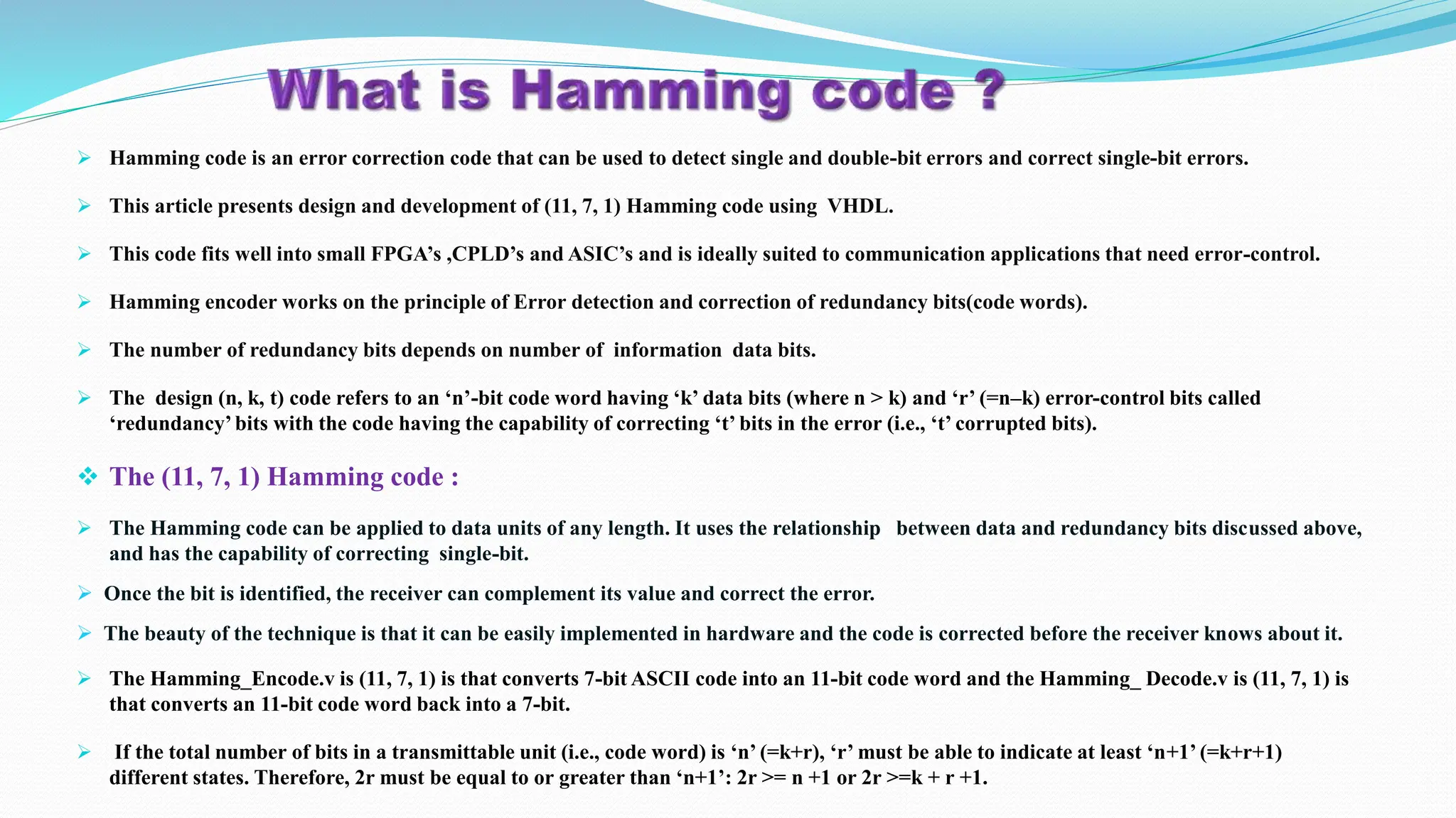
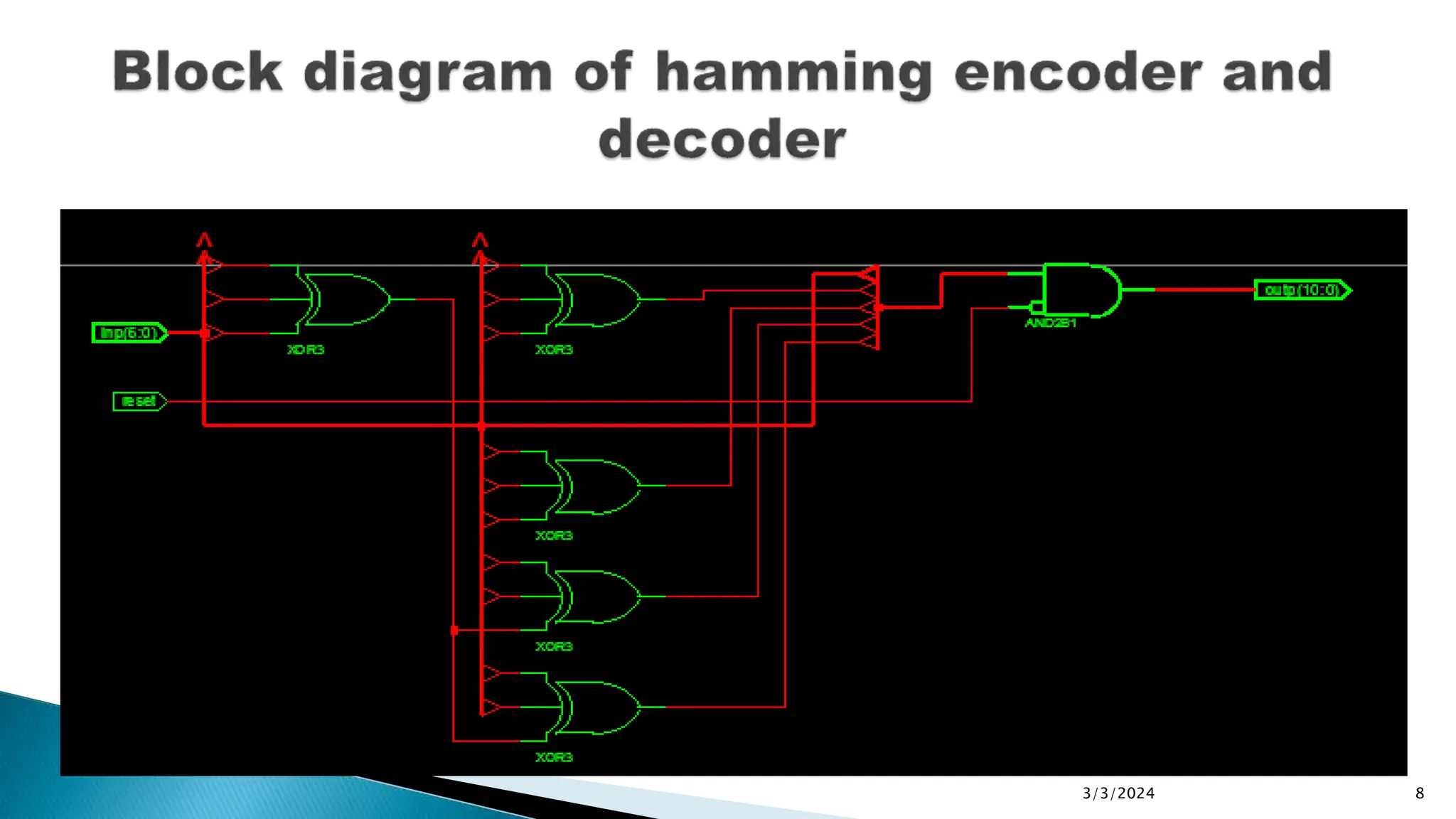
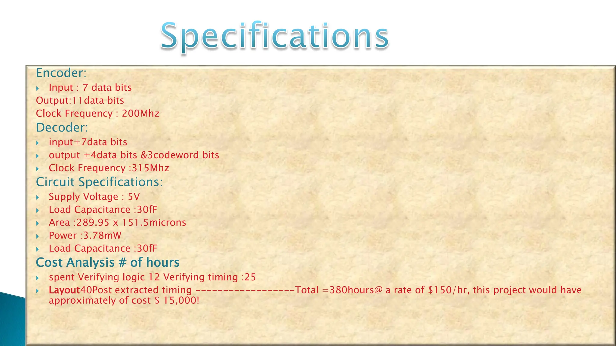
23rd MARCH, 2013
 What is Hamming Code? (abstract) ...3-4  Introduction to Hamming Code ...5-6  Block Diagram Of Hamming Encoder ...7  Project Specifications ...8  Verilog Program for Hamming Encoder And Hamming Decoder ...9-11  Applications And Advantages ...12-14  Conclusion And References ...15-16 AGENDA
 Hamming code is an error correction code that can be used to detect single and double-bit errors and correct single-bit errors.  This article presents design and development of (11, 7, 1) Hamming code using VHDL.  This code fits well into small FPGA’s ,CPLD’s and ASIC’s and is ideally suited to communication applications that need error-control.  Hamming encoder works on the principle of Error detection and correction of redundancy bits(code words).  The number of redundancy bits depends on number of information data bits.  The design (n, k, t) code refers to an ‘n’-bit code word having ‘k’ data bits (where n > k) and ‘r’ (=n–k) error-control bits called ‘redundancy’bits with the code having the capability of correcting ‘t’ bits in the error (i.e., ‘t’ corrupted bits).  The (11, 7, 1) Hamming code :  The Hamming code can be applied to data units of any length. It uses the relationship between data and redundancy bits discussed above, and has the capability of correcting single-bit.  Once the bit is identified, the receiver can complement its value and correct the error.  The beauty of the technique is that it can be easily implemented in hardware and the code is corrected before the receiver knows about it.  The Hamming_Encode.v is (11, 7, 1) is that converts 7-bit ASCII code into an 11-bit code word and the Hamming_ Decode.v is (11, 7, 1) is that converts an 11-bit code word back into a 7-bit.  If the total number of bits in a transmittable unit (i.e., code word) is ‘n’ (=k+r), ‘r’ must be able to indicate at least ‘n+1’ (=k+r+1) different states. Therefore, 2r must be equal to or greater than ‘n+1’: 2r >= n +1 or 2r >=k + r +1.
 Verilog is a general-purpose hardware description language that is easy to learn and use.  It is similar in syntax to the ‘C’ programming language.  Verilog allows different levels of abstraction to be mixed in the same model.  Thus a designer can define a hardware model in terms of gates, switches, register transfer level (RTL) or algorithmic / behavioural code.  Verilog should not be confused with VHDL, which is yet another HDL whose first letter stands for ‘Very High-speed Integrated Circuit’ (VHSIC). INTRODUCTION of VHDL
Error Detection and Correction: Parity Check Method were used before in which odd and even parity bits has errors. Hamming code is an improvement on parity check method. Hamming code method works on only two methods (even parity, odd parity) for generating redundancy bit. The number of redundancy depends on the number of information data bits . Formula for generating redundancy bit ---- 2^ r >= D + r + 1.  Suppose that by the time the above transmission is received, the seventh bit has changed from ‘1’ to ‘0.’ The receiver takes the transmission and recalculates four new parity bits, using the same sets of bits used by the sender plus the relevant parity ‘r’ bit for each set .Then it assembles the new parity values into a binary number in the descending order of ‘r’ position (r8, r4, r2, r1).  In the given example, this step gives us the binary number ‘0111’ (‘7’decimal), which is the precise location of the corrupted bit. Once the bit is identified, the receiver can complement its value and correct the error.
 Hamming code is a set of error-correction codes that can be used to detect and correct bit errors that can occur when computer data is moved or stored. Like other error-correction code, Hamming code makes use of the concept of parity and parity bits, which are bits that are added to data so that the validity of the data can be checked when it is read or after it has been received in a data transmission.  Using more than one parity bit, an error-correction code can not only identify a single bit error in the data unit, but also its location in the data unit. In data transmission, the ability of a receiving station to correct errors in the received data is called forward error correction (FEC) and can increase throughput on a data link when there is a lot of noise present. To enable this, a transmitting station must add extra data (called error correction bits ) to the transmission.  However, the correction may not always represent a cost saving over that of simply resending the information. Hamming codes make FEC less expensive to implement through the use of a block parity mechanism.  Computing parity involves counting the number of ones in a unit of data, and adding either a zero or a one (called a parity bit ) .  The number of parity bits required depends on the number of bits in the data transmission, and is calculated by the  Hamming rule : d + p + l < =2(l). Where d is number of data bits and p is the number of parity bits. The total of the two is called the Hamming code word, which is generated by multiplying the data bits by a generator matrix.
3/3/2024 8
Encoder:  Input : 7 data bits Output:11data bits Clock Frequency : 200Mhz Decoder:  input±7data bits  output ±4data bits &3codeword bits  Clock Frequency :315Mhz Circuit Specifications:  Supply Voltage : 5V  Load Capacitance :30fF  Area :289.95 x 151.5microns  Power :3.78mW  Load Capacitance :30fF Cost Analysis # of hours  spent Verifying logic 12 Verifying timing :25  Layout40Post extracted timing ------------------Total =380hours@ a rate of $150/hr, this project would have approximately of cost $ 15,000!
 Hamming code methodologies is capable for detecting 2 bit error and correcting single bit error.  When we use Hamming code methodology for communication, if single bit error is occurred due to noisy channel no need to retransmit data string again for proper communication because it is able to correct single bit error. Here, we design system, to be able to communicate in full duplex mode with 25 bit information data string by even parity and odd parity check method.  The application of this system is that now we can communicate with 25 bit information data string in full duplex mode.  Error detection and correction codes are used in many common systems including: storage devices (CD, DVD, and DRAM), mobile communication (cellular telephones, wireless, and microwave links), digital television, and high-speed modems (ADSL, xDSL).
 Communication is possible by 7 bit information data string only. Later communication is possible by 25 bit information data string. But till now, communication is possible in simplex mode only by transmitting 30 bit data string with even parity and odd parity check method for 25 bit information data.  Speed of communication system also depends on the number of frame (combination of number of bit is called frame) that can be transmitted in a second.  To increase the speed of communication system increases the number of frame per second or increase the number of bits in a frame. Here we have increased the frame size to increase the number of bits in a single frame. Up to today we can transmit only 11 bit (7 bit data and 4 redundancy bit) in a frame but now we can transmit 31 bits (25 bit information data with 5 redundancy bit and „one‟ extra bit for parity decide) in a single frame.
 The overall conclusion is that, now communication is possible in full duplex mode with 25 bit information data string without retransmit data string if any single bit error is occurred.  Both sections are capable to generate31 bit data string for transmit 25 bit information data with even parity and odd parity check method.  Here we have increased the frame size to increase the number of bits in a single frame. Up to today we can transmit only 11 bit (7 bit data and 4 redundancy bit) in a frame.  But now we can transmit 31 bit (25 bit information data with 5 redundancy bit and one parity decide bit) in a single frame.
 [1] Brajesh Kumar Gupta, Rajeshwar Lal Dua, “30 bit Hamming code for Error Detection and correction using VHDL” National Journal of Engineering Science And Management (ISSN : 2249-0264) volume number I issue II .  [2]. Data communication and networking , Behrouz A. Forouzan , 2nd edition Tata McGraw Hill publication  [3]. http://www.pragsoft.com/books/CommNetwork.pdf  [4]. http://www.eng.uwaterloo.ca/~tnaqvi/downloads/DOC/sd192/ISE8_1i_manuals.pdf  [5]. http://www.xilinx.com/training/xilinx-training-courses.pdf  [6]. http://www.xilinx.com/itp/xilinx10/books/docs/qst/qst.pdf  [7]. http://en.wikipedia.org/wiki/VHDL  [8]. http://www.doulos.com/knowhow/vhdl_designers_guide/  [9]. Digital Logic Design with VHDL , Stephen Brown & Zvonko Vranesic , 2 nd edition TMH publication  [10]. Hamming r.w error detection and correction code, bell sys. Tech. J.29:147-60 1950 bell telefone laboratories ,murray hill  [11].Http://www.britannica.com/ebchecked/topic/585799/telecommunication/76275/repetition- codes#ref608200-  [12]. Http://www.britannica.com/ebchecked/topic/253662/richard-wesley-hamming#ref1073410  [13] ISE 10.1 Quick Start Tutorial, available at http://www.xilinx.com/itp/xilinx10/books/docs/qst/qst.pdf  [14] VHDL (VHSIC hardware description language): http://en.wikipedia.org/wiki/VHDL
Sai Kishore, Rajesh, Venkat Ram Reddy. 20/03/2013 15 Under the esteemed guidance of INTERNAL GUIDE: MR. B.J.SUNIL, ASSOCIATE PROFESSOR, ECE DEPARTMENT.
QUERIES Sai Kishore Rajesh Venkat Ram Reddy

Presentation for the Project on VLSI and Embedded

  • 1.
  • 2.
     What isHamming Code? (abstract) ...3-4  Introduction to Hamming Code ...5-6  Block Diagram Of Hamming Encoder ...7  Project Specifications ...8  Verilog Program for Hamming Encoder And Hamming Decoder ...9-11  Applications And Advantages ...12-14  Conclusion And References ...15-16 AGENDA
  • 3.
     Hamming codeis an error correction code that can be used to detect single and double-bit errors and correct single-bit errors.  This article presents design and development of (11, 7, 1) Hamming code using VHDL.  This code fits well into small FPGA’s ,CPLD’s and ASIC’s and is ideally suited to communication applications that need error-control.  Hamming encoder works on the principle of Error detection and correction of redundancy bits(code words).  The number of redundancy bits depends on number of information data bits.  The design (n, k, t) code refers to an ‘n’-bit code word having ‘k’ data bits (where n > k) and ‘r’ (=n–k) error-control bits called ‘redundancy’bits with the code having the capability of correcting ‘t’ bits in the error (i.e., ‘t’ corrupted bits).  The (11, 7, 1) Hamming code :  The Hamming code can be applied to data units of any length. It uses the relationship between data and redundancy bits discussed above, and has the capability of correcting single-bit.  Once the bit is identified, the receiver can complement its value and correct the error.  The beauty of the technique is that it can be easily implemented in hardware and the code is corrected before the receiver knows about it.  The Hamming_Encode.v is (11, 7, 1) is that converts 7-bit ASCII code into an 11-bit code word and the Hamming_ Decode.v is (11, 7, 1) is that converts an 11-bit code word back into a 7-bit.  If the total number of bits in a transmittable unit (i.e., code word) is ‘n’ (=k+r), ‘r’ must be able to indicate at least ‘n+1’ (=k+r+1) different states. Therefore, 2r must be equal to or greater than ‘n+1’: 2r >= n +1 or 2r >=k + r +1.
  • 4.
     Verilog isa general-purpose hardware description language that is easy to learn and use.  It is similar in syntax to the ‘C’ programming language.  Verilog allows different levels of abstraction to be mixed in the same model.  Thus a designer can define a hardware model in terms of gates, switches, register transfer level (RTL) or algorithmic / behavioural code.  Verilog should not be confused with VHDL, which is yet another HDL whose first letter stands for ‘Very High-speed Integrated Circuit’ (VHSIC). INTRODUCTION of VHDL
  • 5.
    Error Detection andCorrection: Parity Check Method were used before in which odd and even parity bits has errors. Hamming code is an improvement on parity check method. Hamming code method works on only two methods (even parity, odd parity) for generating redundancy bit. The number of redundancy depends on the number of information data bits . Formula for generating redundancy bit ---- 2^ r >= D + r + 1.  Suppose that by the time the above transmission is received, the seventh bit has changed from ‘1’ to ‘0.’ The receiver takes the transmission and recalculates four new parity bits, using the same sets of bits used by the sender plus the relevant parity ‘r’ bit for each set .Then it assembles the new parity values into a binary number in the descending order of ‘r’ position (r8, r4, r2, r1).  In the given example, this step gives us the binary number ‘0111’ (‘7’decimal), which is the precise location of the corrupted bit. Once the bit is identified, the receiver can complement its value and correct the error.
  • 6.
     Hamming codeis a set of error-correction codes that can be used to detect and correct bit errors that can occur when computer data is moved or stored. Like other error-correction code, Hamming code makes use of the concept of parity and parity bits, which are bits that are added to data so that the validity of the data can be checked when it is read or after it has been received in a data transmission.  Using more than one parity bit, an error-correction code can not only identify a single bit error in the data unit, but also its location in the data unit. In data transmission, the ability of a receiving station to correct errors in the received data is called forward error correction (FEC) and can increase throughput on a data link when there is a lot of noise present. To enable this, a transmitting station must add extra data (called error correction bits ) to the transmission.  However, the correction may not always represent a cost saving over that of simply resending the information. Hamming codes make FEC less expensive to implement through the use of a block parity mechanism.  Computing parity involves counting the number of ones in a unit of data, and adding either a zero or a one (called a parity bit ) .  The number of parity bits required depends on the number of bits in the data transmission, and is calculated by the  Hamming rule : d + p + l < =2(l). Where d is number of data bits and p is the number of parity bits. The total of the two is called the Hamming code word, which is generated by multiplying the data bits by a generator matrix.
  • 8.
  • 9.
    Encoder:  Input :7 data bits Output:11data bits Clock Frequency : 200Mhz Decoder:  input±7data bits  output ±4data bits &3codeword bits  Clock Frequency :315Mhz Circuit Specifications:  Supply Voltage : 5V  Load Capacitance :30fF  Area :289.95 x 151.5microns  Power :3.78mW  Load Capacitance :30fF Cost Analysis # of hours  spent Verifying logic 12 Verifying timing :25  Layout40Post extracted timing ------------------Total =380hours@ a rate of $150/hr, this project would have approximately of cost $ 15,000!
  • 10.
     Hamming codemethodologies is capable for detecting 2 bit error and correcting single bit error.  When we use Hamming code methodology for communication, if single bit error is occurred due to noisy channel no need to retransmit data string again for proper communication because it is able to correct single bit error. Here, we design system, to be able to communicate in full duplex mode with 25 bit information data string by even parity and odd parity check method.  The application of this system is that now we can communicate with 25 bit information data string in full duplex mode.  Error detection and correction codes are used in many common systems including: storage devices (CD, DVD, and DRAM), mobile communication (cellular telephones, wireless, and microwave links), digital television, and high-speed modems (ADSL, xDSL).
  • 11.
     Communication ispossible by 7 bit information data string only. Later communication is possible by 25 bit information data string. But till now, communication is possible in simplex mode only by transmitting 30 bit data string with even parity and odd parity check method for 25 bit information data.  Speed of communication system also depends on the number of frame (combination of number of bit is called frame) that can be transmitted in a second.  To increase the speed of communication system increases the number of frame per second or increase the number of bits in a frame. Here we have increased the frame size to increase the number of bits in a single frame. Up to today we can transmit only 11 bit (7 bit data and 4 redundancy bit) in a frame but now we can transmit 31 bits (25 bit information data with 5 redundancy bit and „one‟ extra bit for parity decide) in a single frame.
  • 13.
     The overallconclusion is that, now communication is possible in full duplex mode with 25 bit information data string without retransmit data string if any single bit error is occurred.  Both sections are capable to generate31 bit data string for transmit 25 bit information data with even parity and odd parity check method.  Here we have increased the frame size to increase the number of bits in a single frame. Up to today we can transmit only 11 bit (7 bit data and 4 redundancy bit) in a frame.  But now we can transmit 31 bit (25 bit information data with 5 redundancy bit and one parity decide bit) in a single frame.
  • 14.
     [1] BrajeshKumar Gupta, Rajeshwar Lal Dua, “30 bit Hamming code for Error Detection and correction using VHDL” National Journal of Engineering Science And Management (ISSN : 2249-0264) volume number I issue II .  [2]. Data communication and networking , Behrouz A. Forouzan , 2nd edition Tata McGraw Hill publication  [3]. http://www.pragsoft.com/books/CommNetwork.pdf  [4]. http://www.eng.uwaterloo.ca/~tnaqvi/downloads/DOC/sd192/ISE8_1i_manuals.pdf  [5]. http://www.xilinx.com/training/xilinx-training-courses.pdf  [6]. http://www.xilinx.com/itp/xilinx10/books/docs/qst/qst.pdf  [7]. http://en.wikipedia.org/wiki/VHDL  [8]. http://www.doulos.com/knowhow/vhdl_designers_guide/  [9]. Digital Logic Design with VHDL , Stephen Brown & Zvonko Vranesic , 2 nd edition TMH publication  [10]. Hamming r.w error detection and correction code, bell sys. Tech. J.29:147-60 1950 bell telefone laboratories ,murray hill  [11].Http://www.britannica.com/ebchecked/topic/585799/telecommunication/76275/repetition- codes#ref608200-  [12]. Http://www.britannica.com/ebchecked/topic/253662/richard-wesley-hamming#ref1073410  [13] ISE 10.1 Quick Start Tutorial, available at http://www.xilinx.com/itp/xilinx10/books/docs/qst/qst.pdf  [14] VHDL (VHSIC hardware description language): http://en.wikipedia.org/wiki/VHDL
  • 15.
    Sai Kishore, Rajesh, Venkat RamReddy. 20/03/2013 15 Under the esteemed guidance of INTERNAL GUIDE: MR. B.J.SUNIL, ASSOCIATE PROFESSOR, ECE DEPARTMENT.
  • 16.