Dr. Gargi Khanna discusses error detection and correction codes such as parity codes and Hamming codes. Parity codes add an extra bit to allow detection of errors in transmitted data by checking if the total number of 1s is even or odd. Block parity codes apply this to blocks of data with row and column parity. Hamming codes can detect single and double bit errors using additional parity bits placed in specific bit locations. This allows identification and correction of single bit errors during data transmission.
Dr. (Mrs.) GargiKhanna Associate Professor Electronics & Communication Engg. Deptt.. National Institute of Technology Hamirpur (HP) By:-
2.
o Error detectionand correction Codes o Parity codes o Block Parity Codes o Hamming codes
3.
When thedigital information in the binary form is transmitted from one circuit or system to another circuit or system an error mayoccur due to interference, noise, etc Hence, data will be corrupted This means the signal corresponding to 0 may change to 1 or vice-versa due to presence of noise Need schemes devised to detect and correct the error
4.
• To maintaindata integrity between transmitter and receiver, extra bit or more than one bit are added in the data. • These extra bits allow the detection and sometimes the correction of error in the data. • The data along with the extra bit /bits form the code • Codes which allow only error detection are called error detecting codes and codes which allow error detection and correction are called error detecting and correcting codes 3
• A paritybit is used for the purpose of detecting errors during transmission of binary information. • A parity bit is an extra bit included with a binary message to make the number of 1s either odd ( ODD Parity) or even (EVEN Parity). • The message including the parity bit is transmitted and then checked at the receiving end for errors. • An error is detected if the checked parity does not match with the one transmitted. 3
7.
Even/odd parity: is basic method for detecting if an odd number of bits has been switched by accident. Odd parity: The number of 1-bit must add up to an odd number Even parity: The number of 1-bit must add up to an even number
8.
• The circuitthat generates the parity bit in the transmitter is called a parity generator and the circuit that checks the parity in the receiver is called a parity checker. • As a general rule in the digital system where the transmission system is relatively short, it may be assumed that probability of a single-bit error is small and that of a double-bit error and higher order errors is extremely small. The parity error detection system detects any odd number of errors. However, it can not detect even number of errors as such errors will not destroy the parity of the transmitted group of bits 8
9.
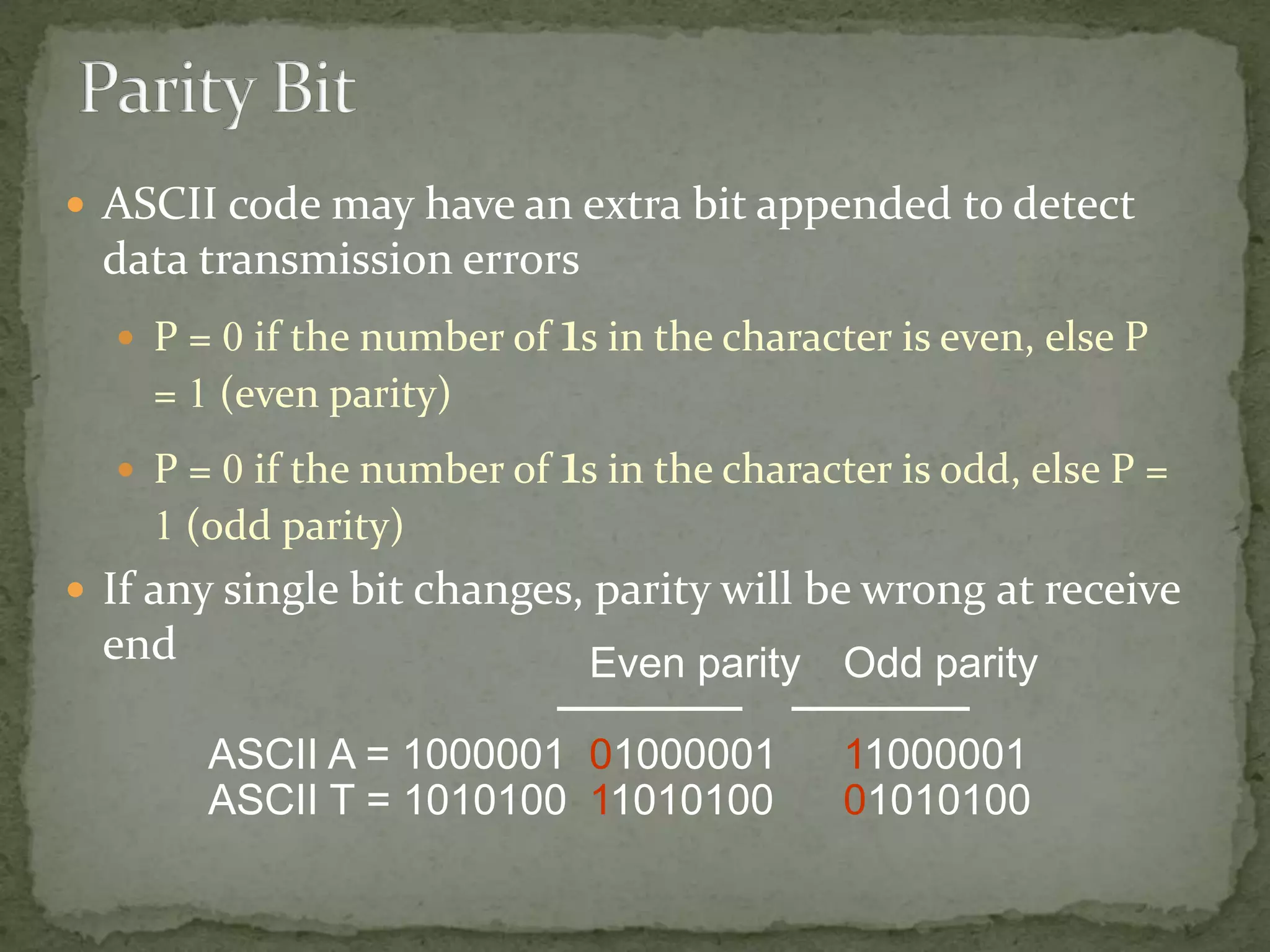
ASCII codemay have an extra bit appended to detect data transmission errors P = 0 if the number of 1s in the character is even, else P = 1 (even parity) P = 0 if the number of 1s in the character is odd, else P = 1 (odd parity) If any single bit changes, parity will be wrong at receive end Even parity Odd parity ASCII A = 1000001 01000001 11000001 ASCII T = 1010100 11010100 01010100
10.
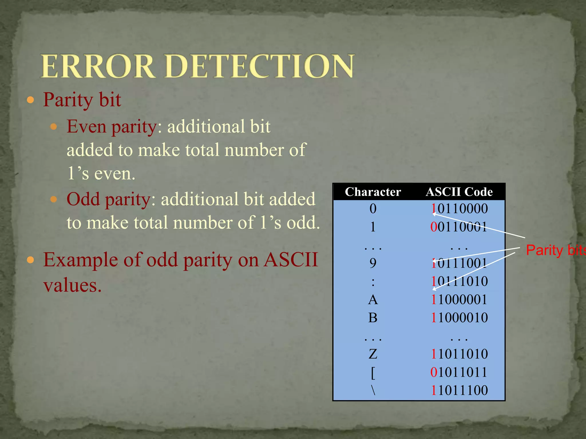
Parity bit Even parity: additional bit added to make total number of 1’s even. Odd parity: additional bit added to make total number of 1’s odd. Example of odd parity on ASCII values. Character ASCII Code 0 10110000 1 00110001 . . . . . . 9 10111001 : 10111010 A 11000001 B 11000010 . . . . . . Z 11011010 [ 01011011 11011100 Parity bits
11.
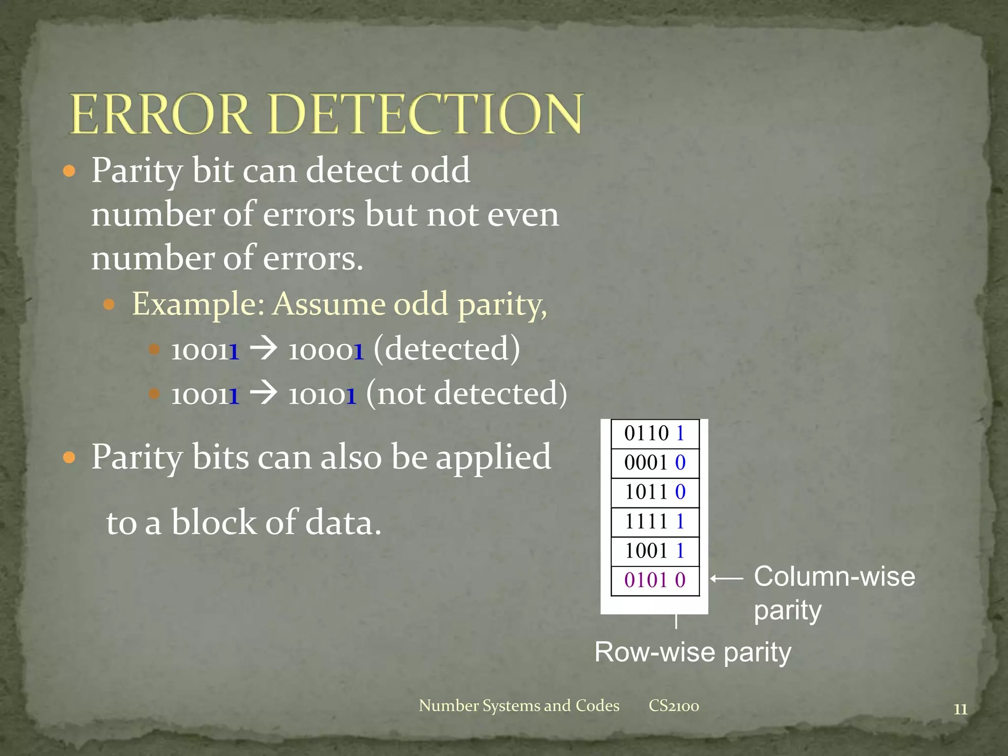
Parity bitcan detect odd number of errors but not even number of errors. Example: Assume odd parity, 10011 10001 (detected) 10011 10101 (not detected) Parity bits can also be applied to a block of data. CS2100 Number Systems and Codes 11 0110 1 0001 0 1011 0 1111 1 1001 1 0101 0 Column-wise parity Row-wise parity
12.
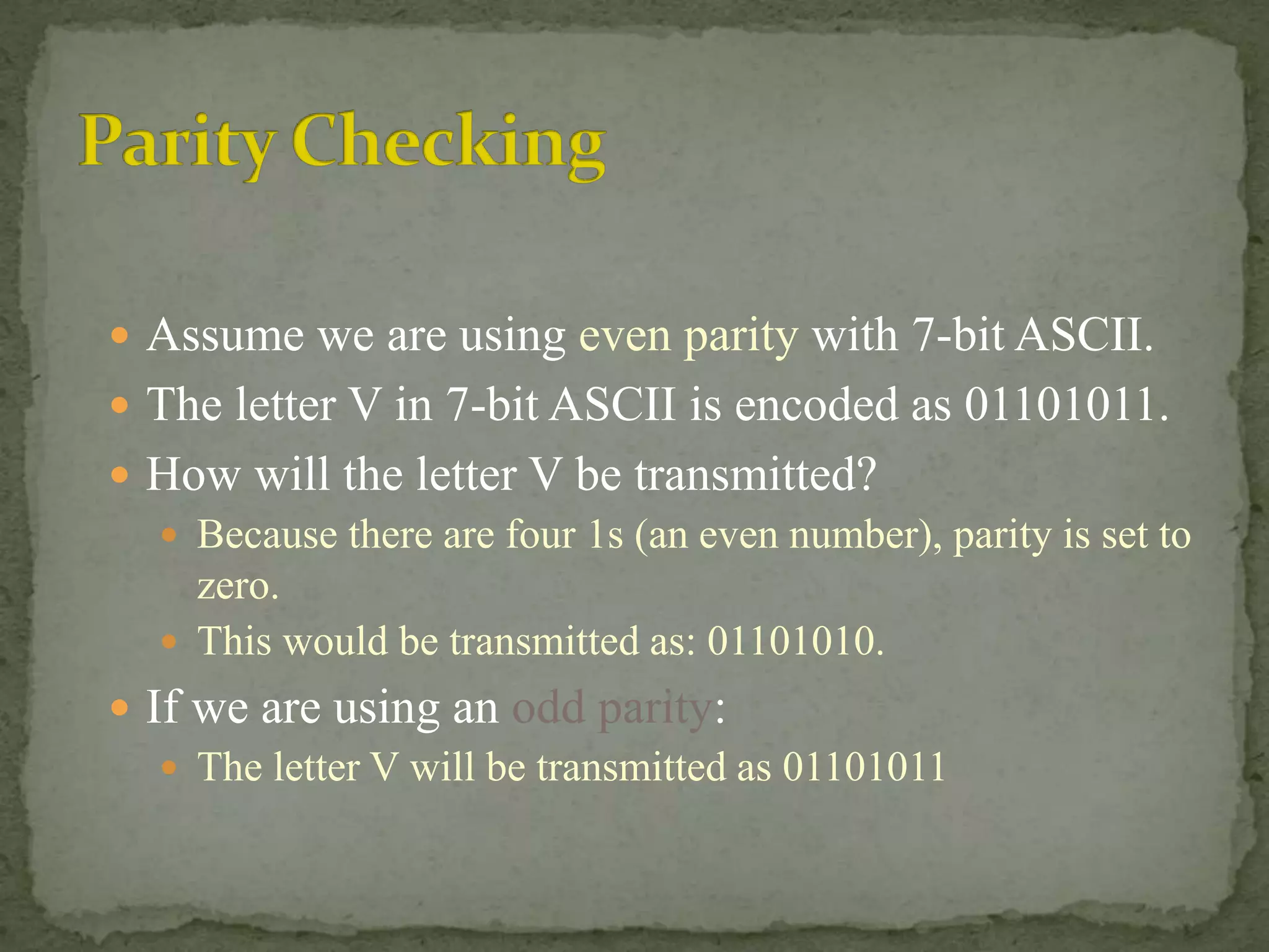
Assume weare using even parity with 7-bit ASCII. The letter V in 7-bit ASCII is encoded as 01101011. How will the letter V be transmitted? Because there are four 1s (an even number), parity is set to zero. This would be transmitted as: 01101010. If we are using an odd parity: The letter V will be transmitted as 01101011
13.
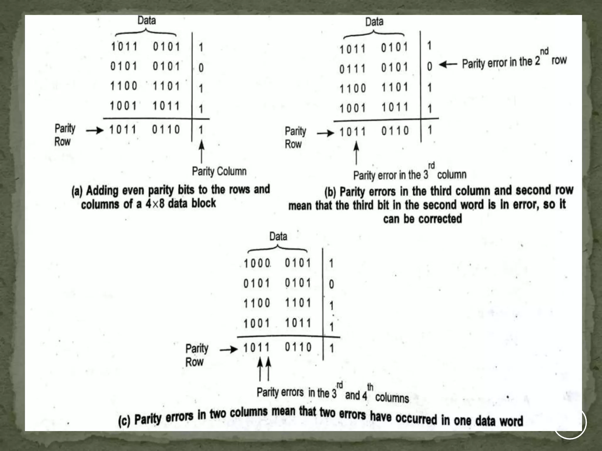
When several binarywords are transmitted or received in succession, the resulting collection of bits can be regarded as a block of data, having rows and columns. Example: four eight bit words in succession form an 4x8 block. Parity bits can then be assigned to both rows and columns. This scheme is known as block parity It makes it possible to correct any single error occurring in a data word and to detect any two errors in a word. 1 3
15.
Sometimes, itis not enough to do error detection. We may want to correct the errors. Error correction is expensive. In practice, we may use only single-bit error correction. Popular technique: Hamming code . CS2100 Number Systems and Codes 15
17.
In thelate 1940’s Richard Hamming recognized that the further evolution of computers required greater reliability, in particular the ability to not only detect errors, but correct them. His search for error- correcting codes led to the Hamming Codes and the extended Hamming Codes.
18.
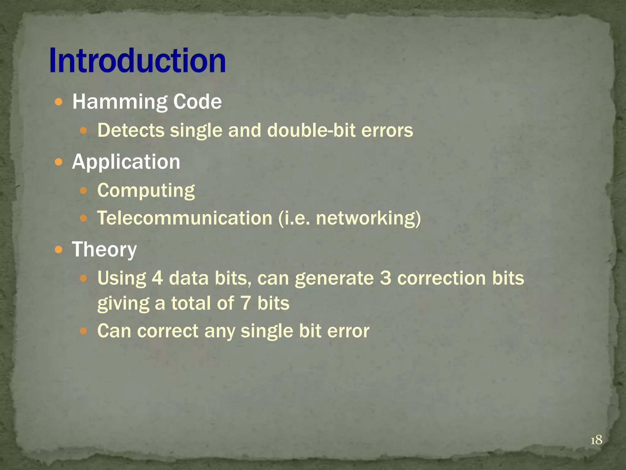
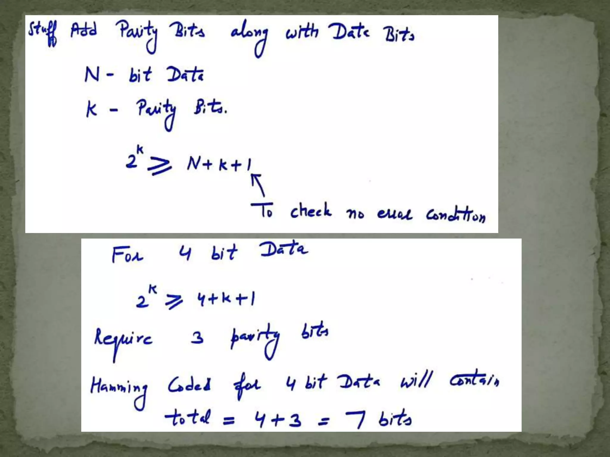
18 Hamming Code Detects single and double-bit errors Application Computing Telecommunication (i.e. networking) Theory Using 4 data bits, can generate 3 correction bits giving a total of 7 bits Can correct any single bit error
19.
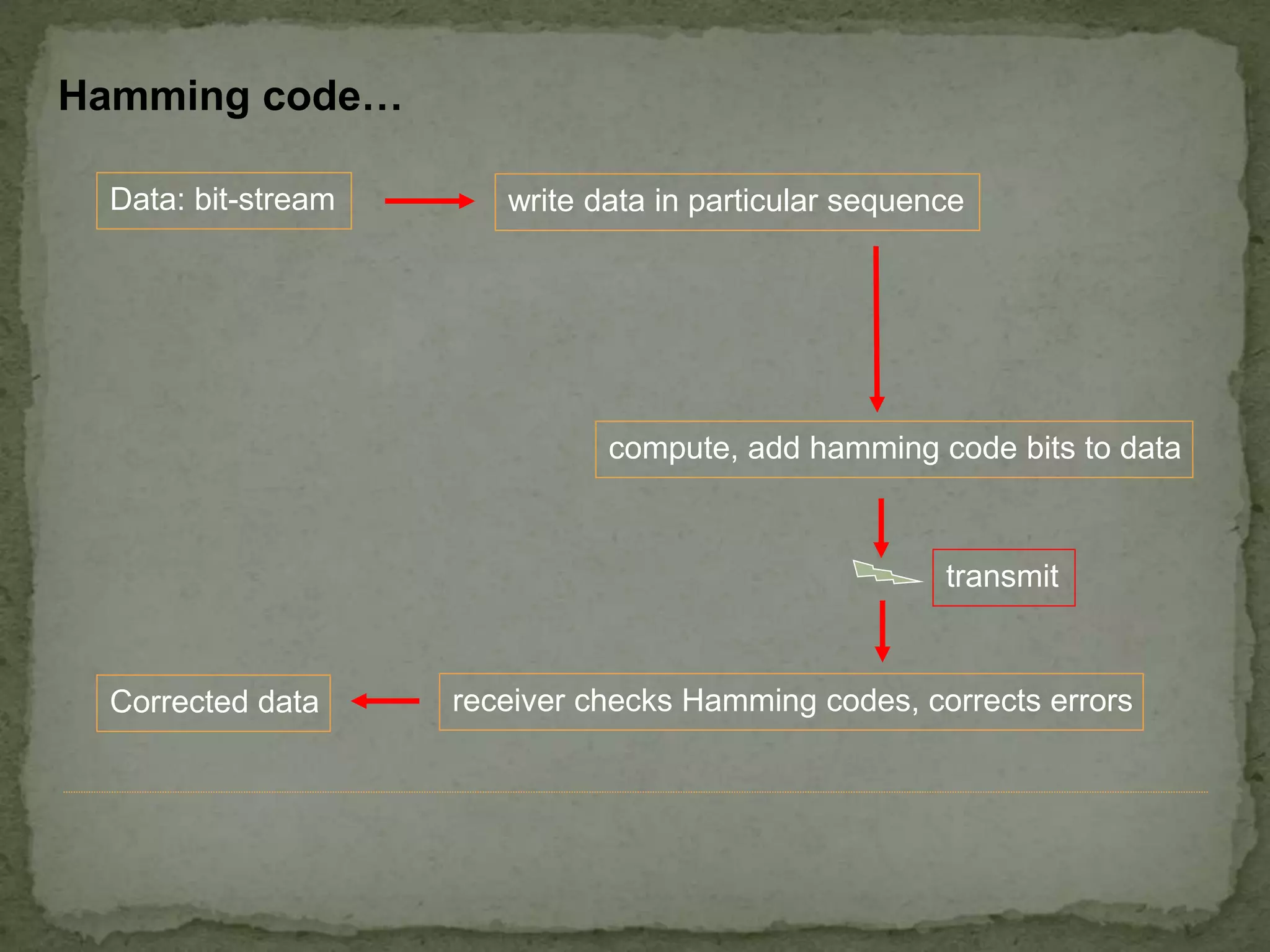
Hamming code… Data: bit-streamwrite data in particular sequence receiver checks Hamming codes, corrects errors transmit compute, add hamming code bits to data Corrected data
20.
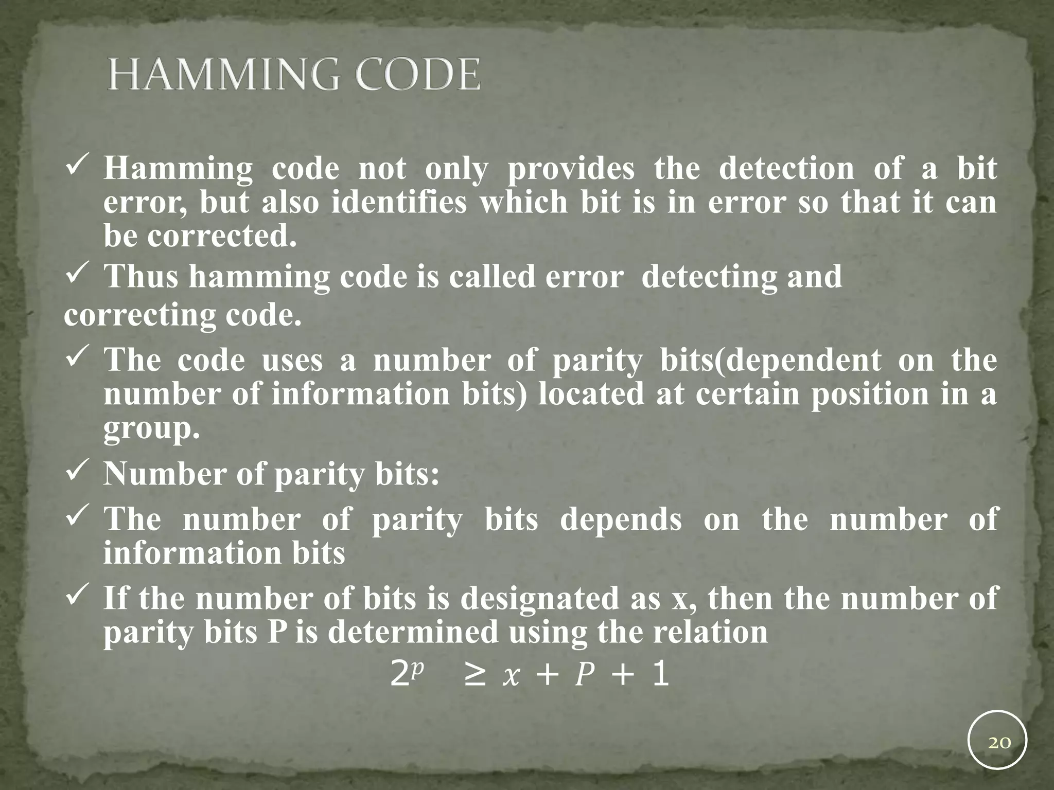
Hamming codenot only provides the detection of a bit error, but also identifies which bit is in error so that it can be corrected. Thus hamming code is called error detecting and correcting code. The code uses a number of parity bits(dependent on the number of information bits) located at certain position in a group. Number of parity bits: The number of parity bits depends on the number of information bits If the number of bits is designated as x, then the number of parity bits P is determined using the relation 2𝑝 ≥ 𝑥 + 𝑃 + 1 20
22.
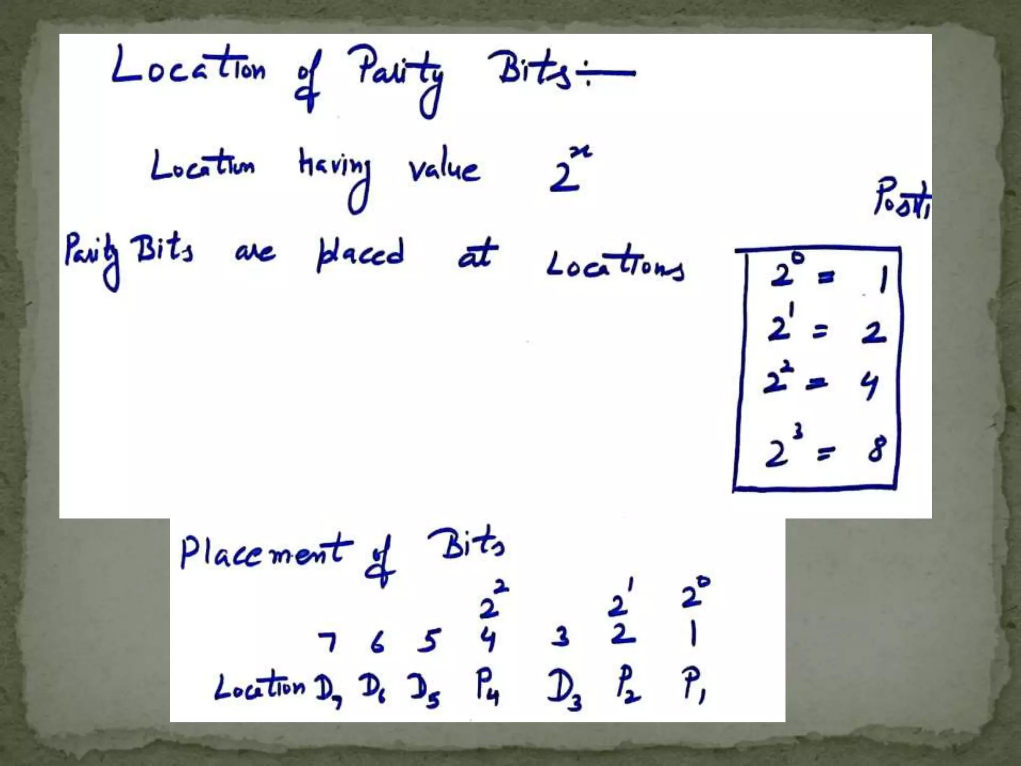
Location of theparity bits in a code: •The parity bits are located in the positions that are numbered corresponding to ascending powers of two(1,2,4,8,….). •Therefore, for 7-bit code, locations for parity bits and information bits are as follows: D4, D3,D2,P3, D1,P2,P1 Assigning values to parity bit: •In hamming code , each parity bit provides a check on certain other bits in the total code, therefore we must know the value of these others in order to assign the parity bit value. 22
24.
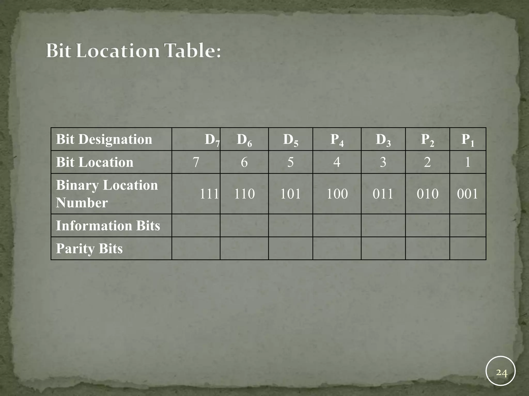
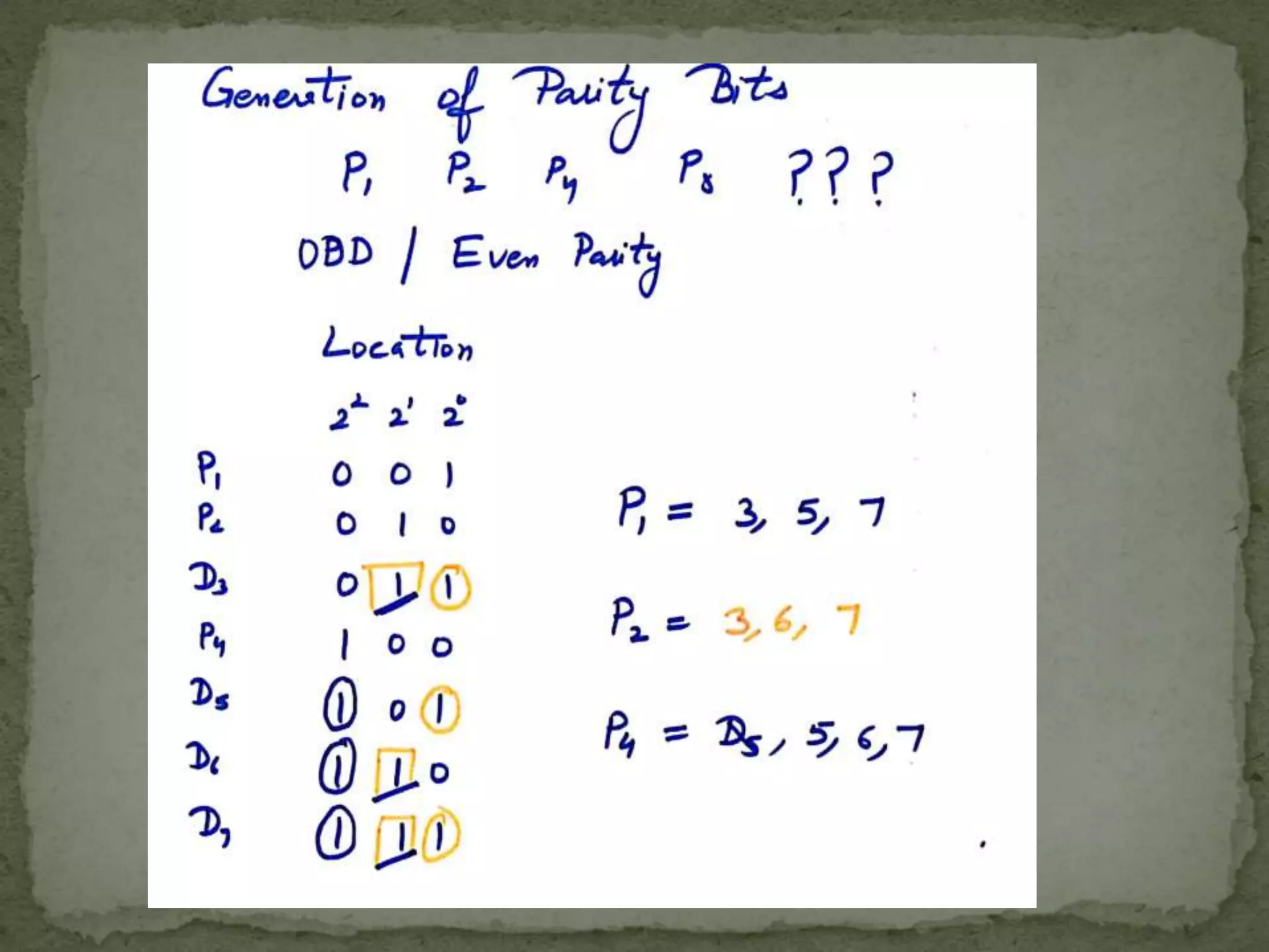
Bit Designation D7D6 D5 P4 D3 P2 P1 Bit Location 7 6 5 4 3 2 1 Binary Location Number 111 110 101 100 011 010 001 Information Bits Parity Bits 24
26.
Assignment of P1: Thisparity bit checks all bit locations, that have 1s in the same location in the binary location numbers. Assignment of P2: This parity bit checks all bit locations, that have 1s in the middle bit. Assignment of P3: This parity bit checks all bit locations, that have 1s in the left-most bit. 26
30.
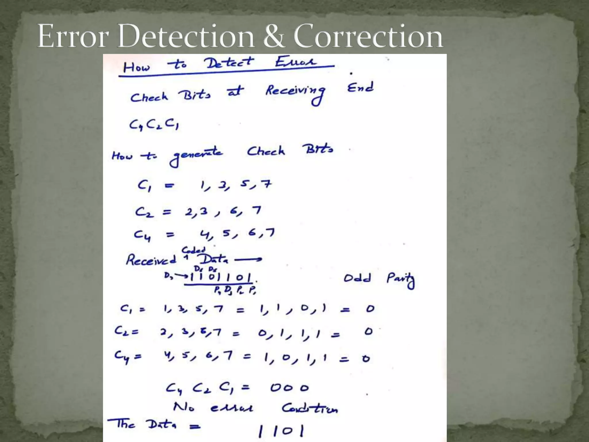
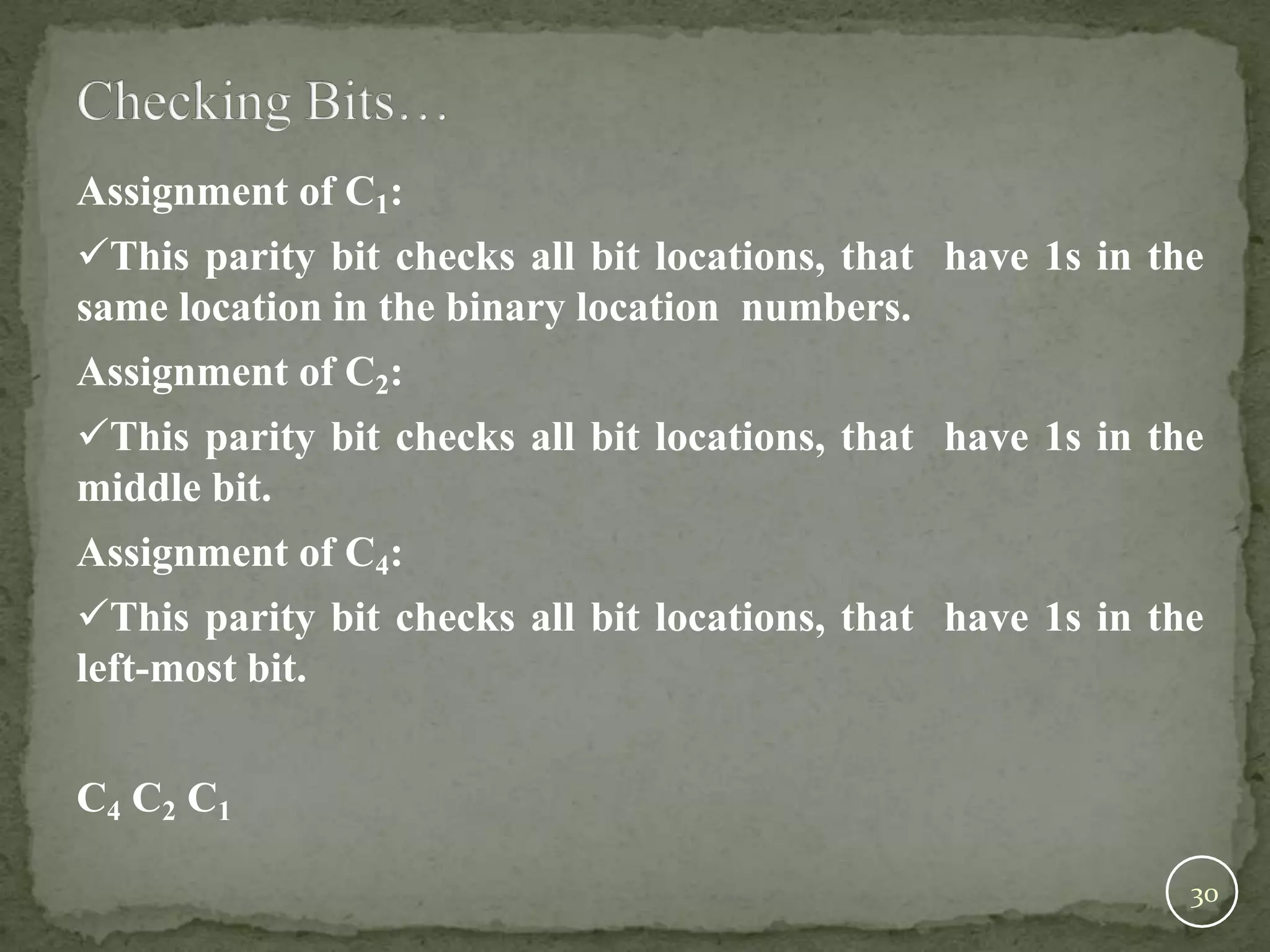
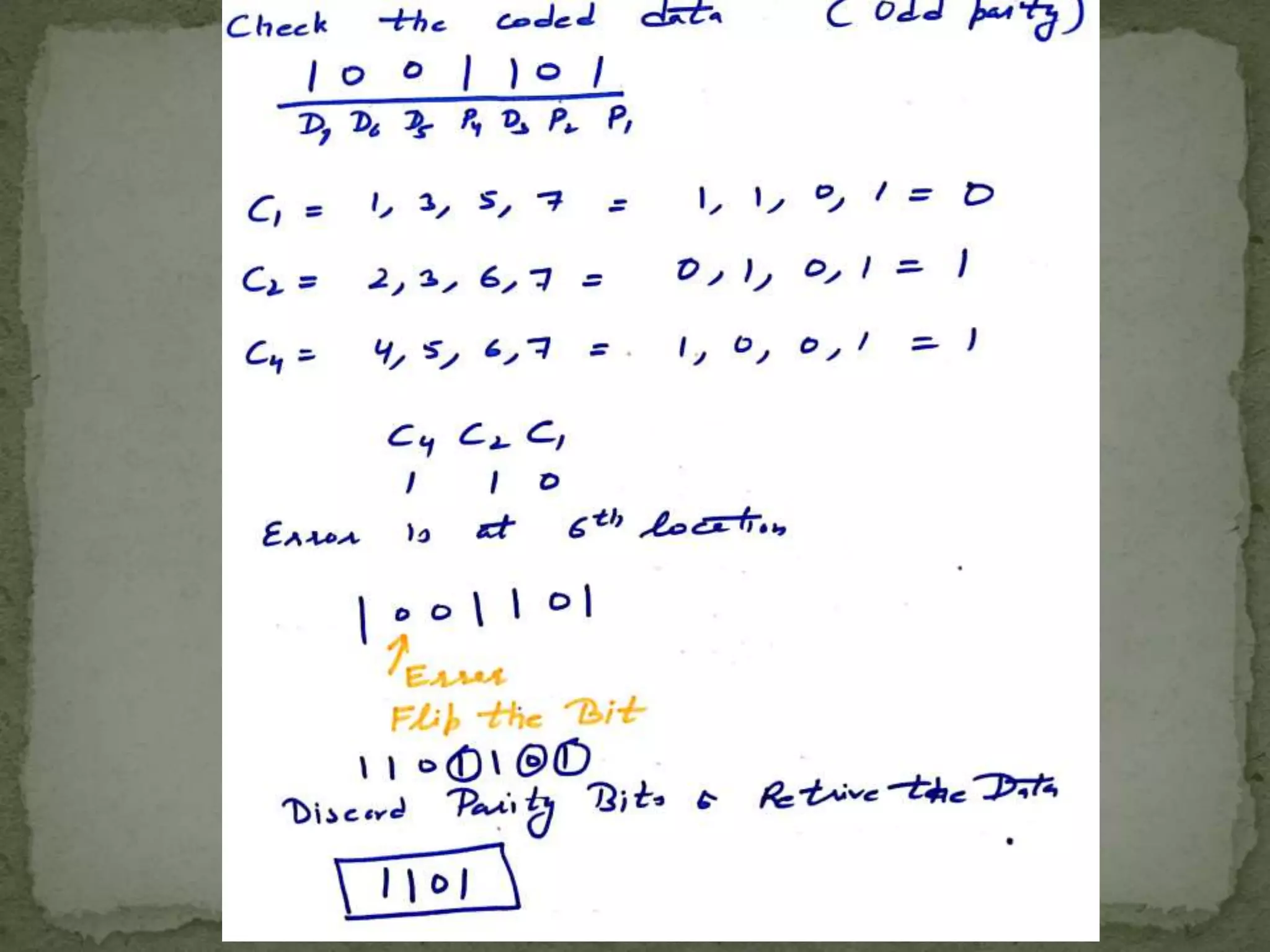
Assignment of C1: Thisparity bit checks all bit locations, that have 1s in the same location in the binary location numbers. Assignment of C2: This parity bit checks all bit locations, that have 1s in the middle bit. Assignment of C4: This parity bit checks all bit locations, that have 1s in the left-most bit. C4 C2 C1 30