Download as PDF, PPTX
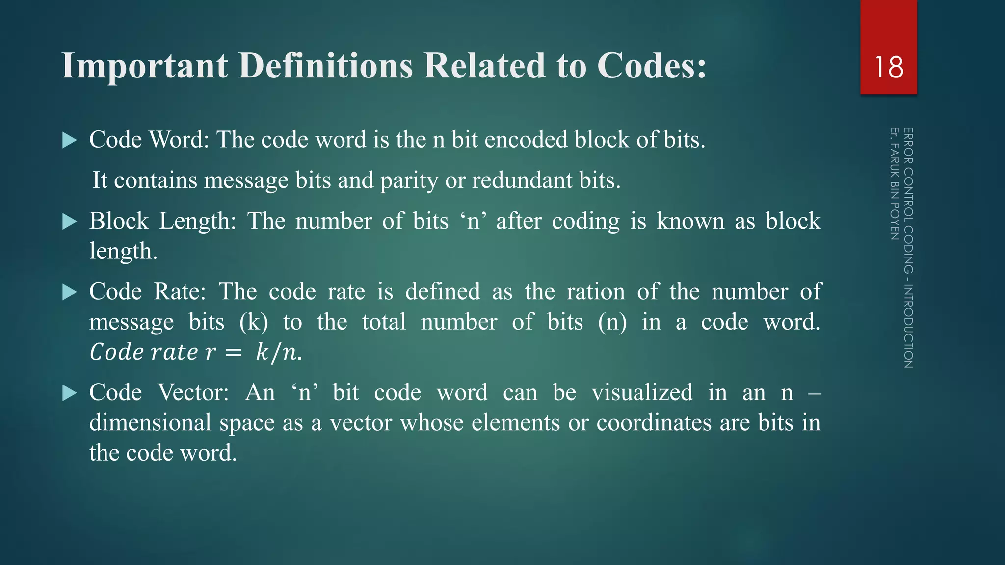
![Important Definitions Related to Codes: Hamming Distance: It is the distance between the two codes expressed in the number of locations in which their respective elements differ. Hamming Weight of a Code Word [w(x)]: It is defined as the number of non – zero elements in the code word. Code Efficiency: It is defined as the ratio of message bits to the number of transmitted bits per block. Code efficiency is equal to that of code rate. Minimum Distance dmin: It is defined as the smallest Hamming distance between any pair of code vectors in the code. 19](https://image.slidesharecdn.com/informationtheorycoding-2-170515093756/75/Error-Control-Coding-Introduction-19-2048.jpg)
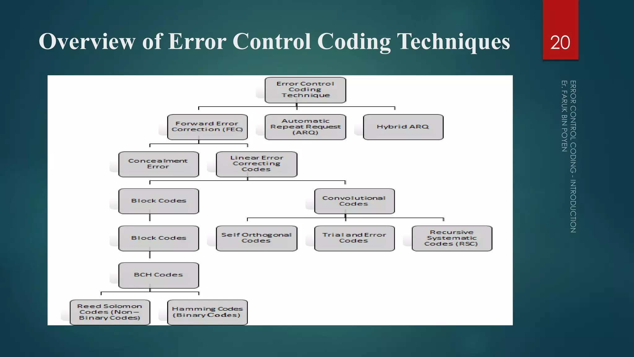
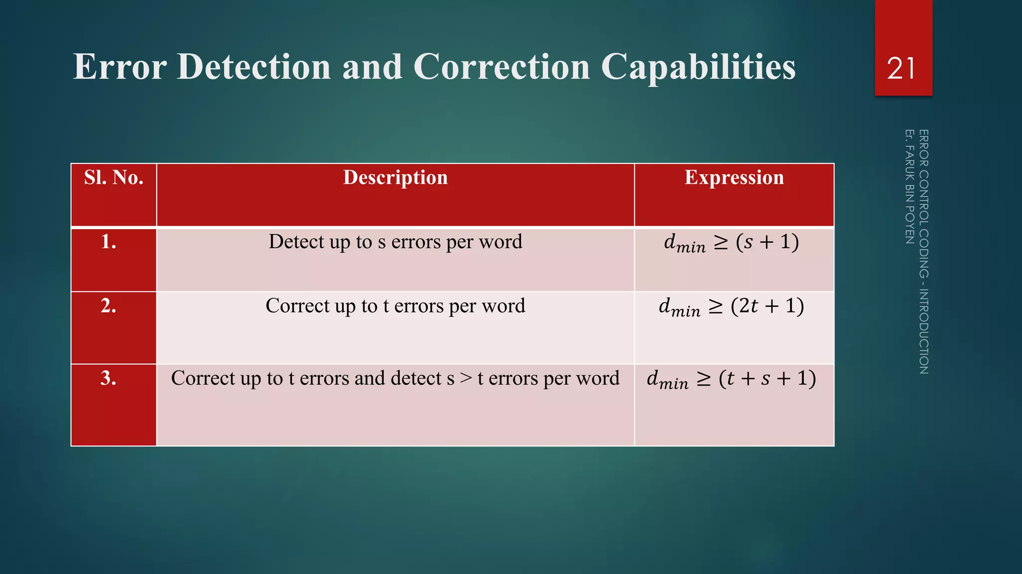


The document provides a comprehensive overview of error control coding, detailing its significance in information theory through categories such as source coding and channel coding. It discusses various coding techniques, including data compression, error detection and correction, classifications of codes, and methods like Automatic Repeat reQuest (ARQ) and Forward Error Correction (FEC). Additionally, it covers the implications of transmission errors and the mathematical foundations underpinning coding theory.