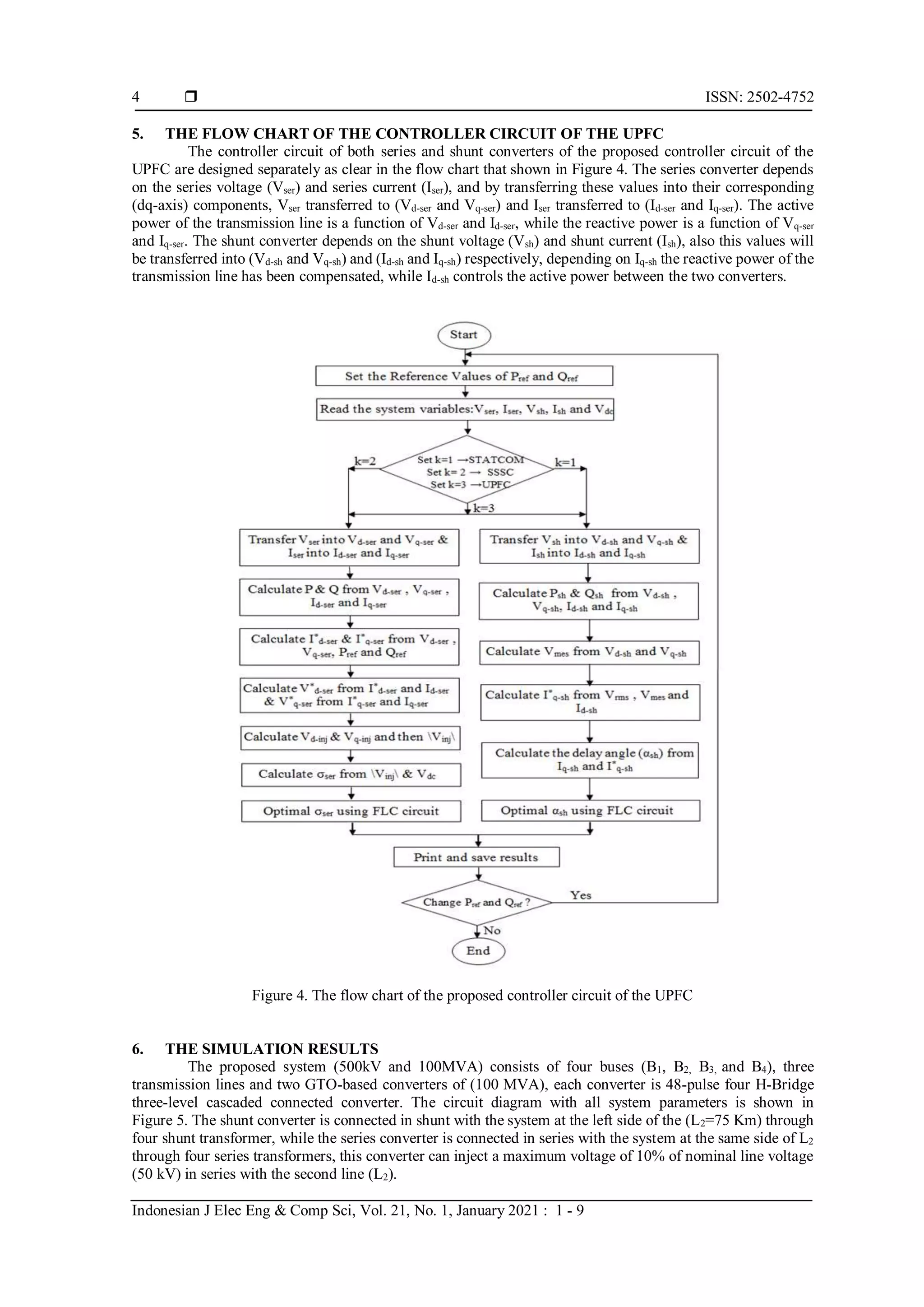
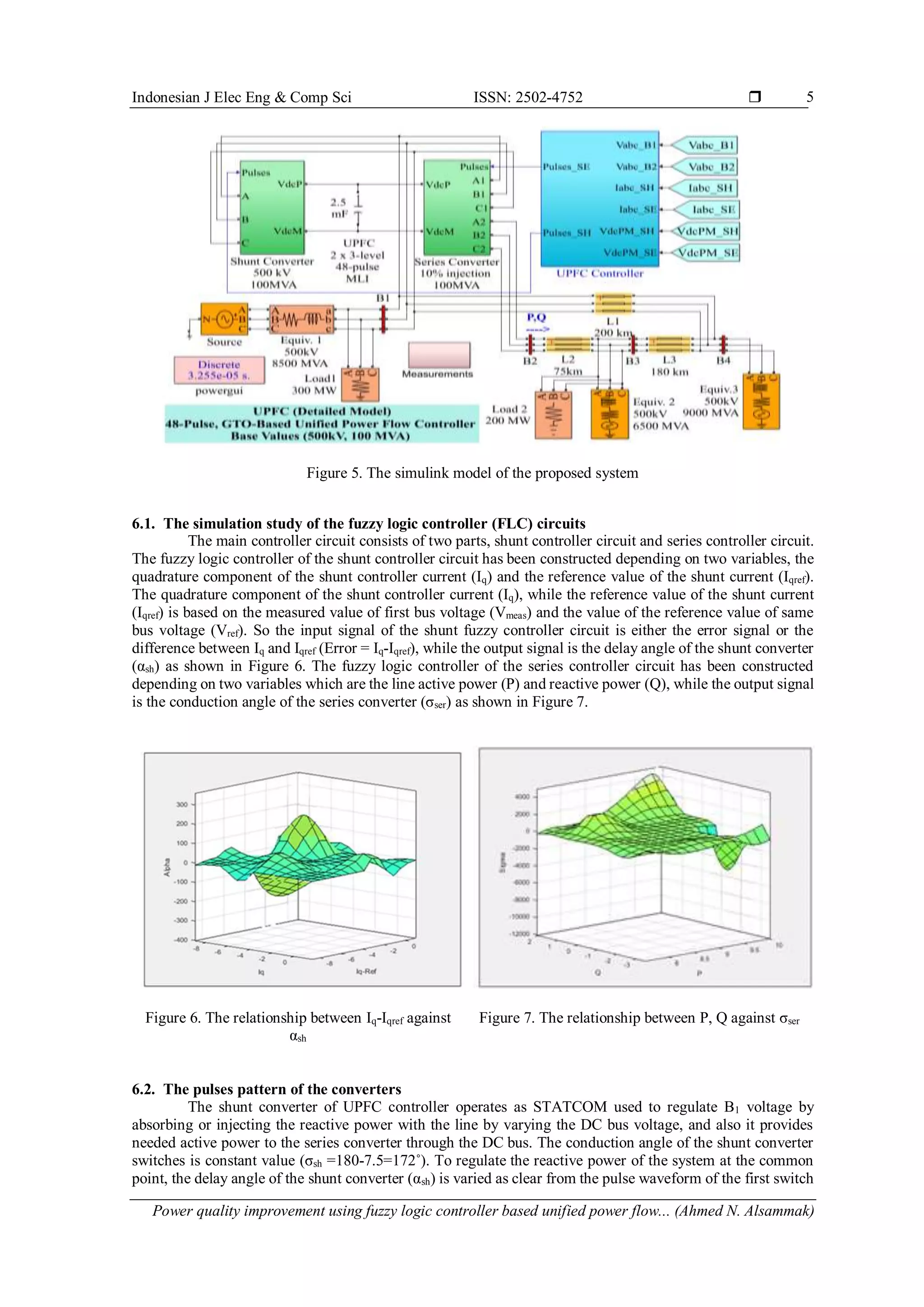
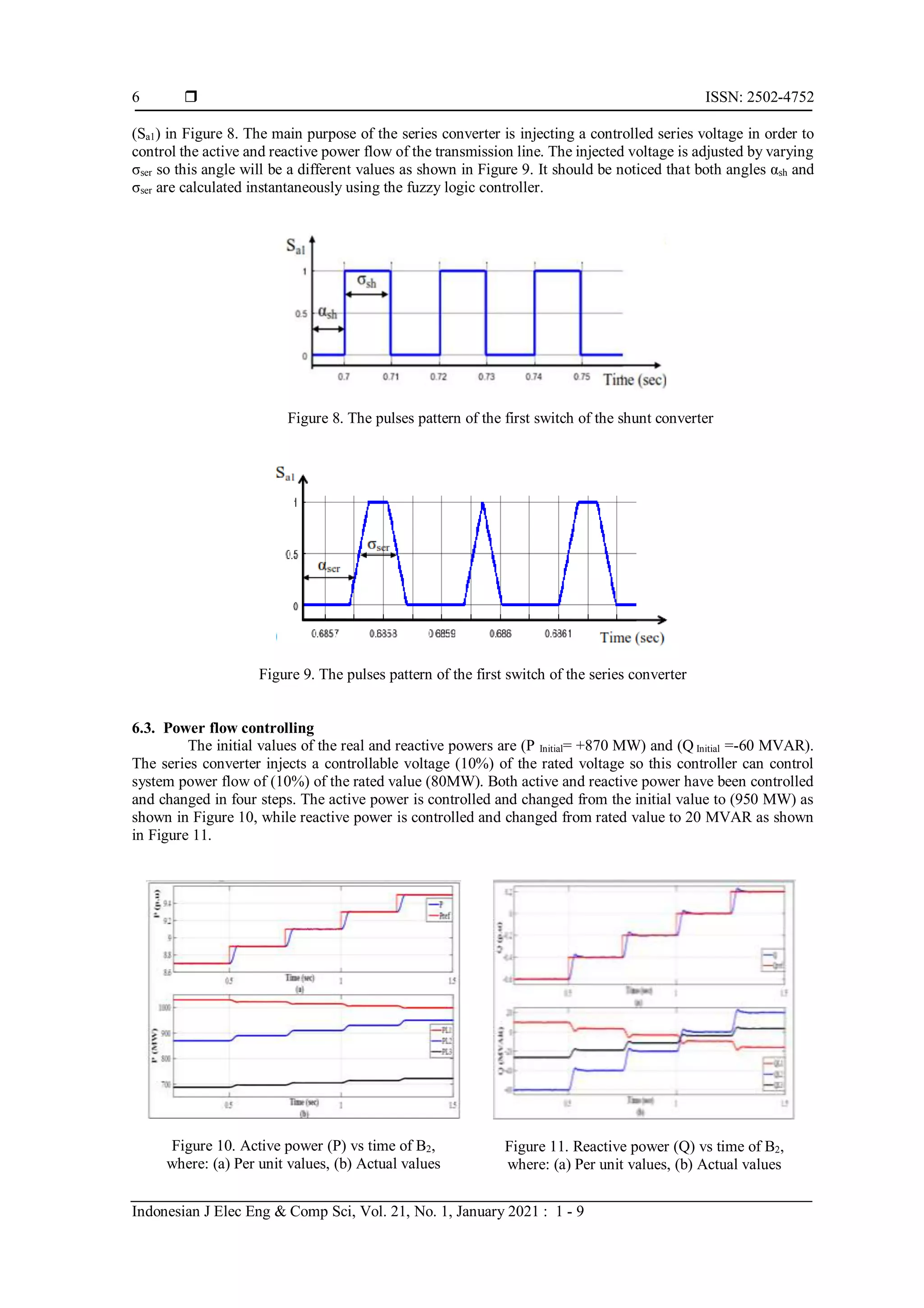
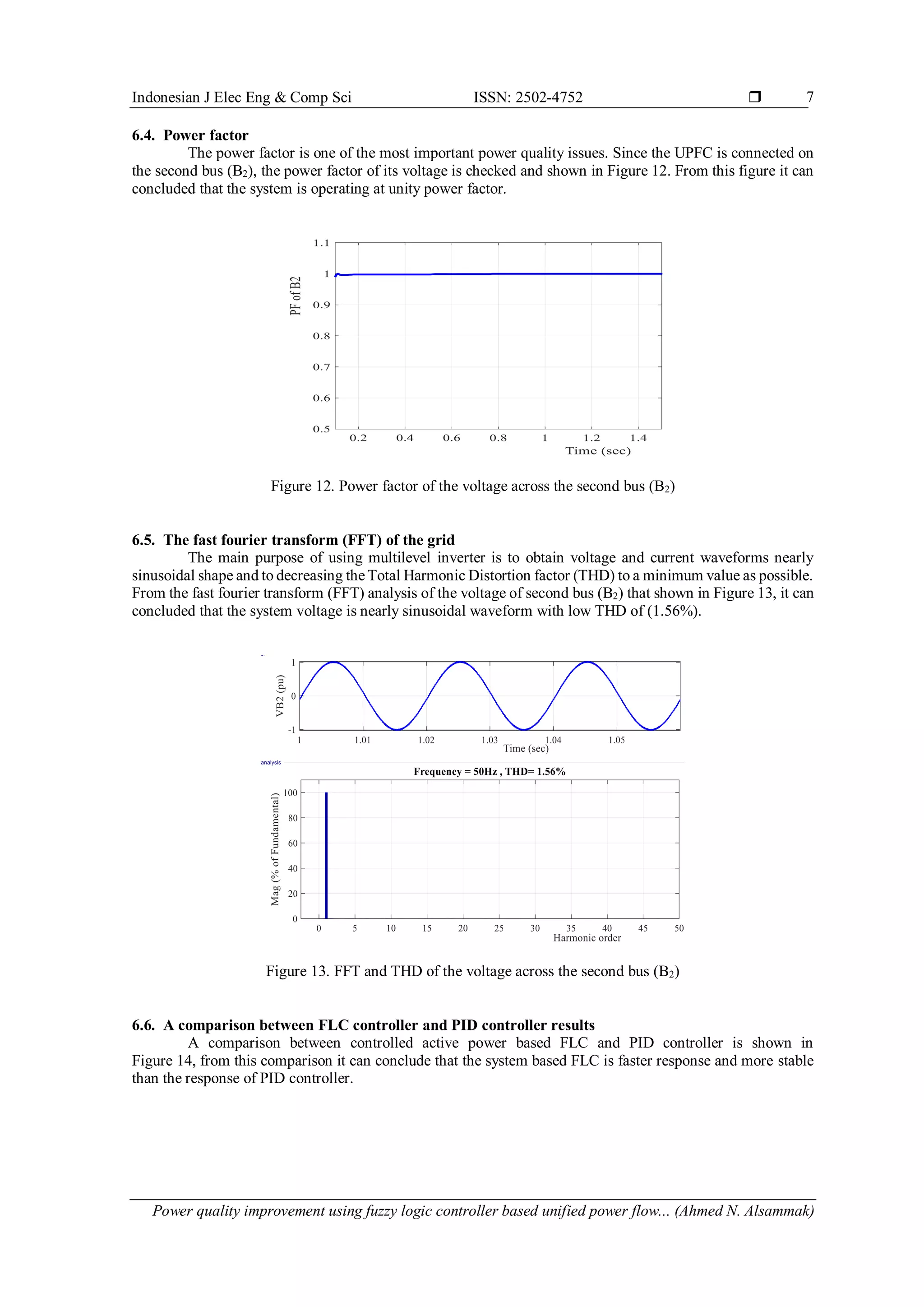
Indonesian Journal of Electrical Engineering and Computer Science Vol. 21, No. 1, January 2021, pp. 1~9 ISSN: 2502-4752, DOI: 10.11591/ijeecs.v21.i1.pp1-9  1 Journal homepage: http://ijeecs.iaescore.com Power quality improvement using fuzzy logic controller based unified power flow controller Ahmed N. Alsammak, Hasan A. Mohammed Department of Electrical Engineering, Colege of Engineering, University of Mosul, Iraq Article Info ABSTRACT Article history: Received Mar 24, 2020 Revised Jun 15, 2020 Accepted Jul 8, 2020 The power quality of the electrical system is an important issue for industrial, commercial, and housing uses. An increasing request for high quality electrical power and an increasing number of distorting loads had led to increase the consideration of power quality by customers and utilities. The development and use of flexible alternating current transmission system (FACTs) controllers in power transmission systems had led to many applications of these controllers. A unified power flow controller (UPFC) is one of the FACTs elements which is used to control both active and reactive power flow of the transmission line. This paper tried to improve power quality using a fuzzy logic controller (FLC) based UPFC, where it used to control both active and reactive power flow, decreas the total harmonic distortion (THD), correct power factor, regulate line voltage and enhance transient stability. A comparison study of the performance between the system with a conventional PID controller and FLC has been done. The theoretical analysis has been proved by implementing the system using MATLAB/SIMULINK package. Keywords: FACTs Power quality SSSC UPFCSTATCOM Voltage stability This is an open access article under the CC BY-SA license. Corresponding Author: Hasan A. Mohammed Department of Electrical Engineering The University of Mosul, Mosul, Iraq Email: hasan82adnan@uomosul.edu.iq 1. INTRODUCTION Recently, the term power quality (PQ) takes more consideration by the electrical engineers. The power quality is a very important issue related to the voltage, current, and frequency of the power system. Many circuits such as magnetic circuits, non-linear loads, converters, and flexible alternating current transmission system (FACTs) devices represent source of harmonics and problems with adversely influence to the power quality. In electrical engineering the term power quality may take several meanings such as (voltage quality), (current quality), (service quality), (supply reliability), (quality of source). The power quality of the power system may be faced with many problems like voltage sag, voltage swell, harmonics distortion, absence or lack of VAR compensation units, voltage interruptions, and transient conditions. To improve the performance of a microgrid, it is required to manage the fluctuation of reactive power efficiently and this is known as reactive power compensation. The FACTs can mitigate electrical power problems in different conditions (steady-state, transient, and post transient steady-state) [1-4]. It can be classified into four types, the first type is shunt controllers such as static synchronous compensator (STATCOM), the second type is series controllers, for example, static synchronous series compensator (SSSC), the third type is a combination between the series and shunt controllers such as unified power flow controller (UPFC) and the final type is a combination between two series controllers such as interline power controller (IPFC) [5-9]. The SSSC is used to control power flow and to improve transient stability [10-12], while the STATCOM
 ISSN: 2502-4752 Indonesian J Elec Eng & Comp Sci, Vol. 21, No. 1, January 2021 : 1 - 9 2 is used to regulate line voltage by injecting or absorbing the reactive power to the system [13-17]. The UPFC is one of the FACTS family members with very versatile uses [18-21], it has the ability to control the transmission line parameters (voltage, impedance, and phase angle) at the same time. It consists of two converters: series converter and a shunt converter are connected by a common DC link capacitor, which can simultaneously control the transmission line active and reactive power flow as well as to UPFC bus voltage [22-24]. This paper presents a simulation study of UPFC, connected with four busses (B1, B2, B3 and B4) system of 100-MVA, 500 KV and two of three-level 48-pulse GTO based converters in order to eliminate the harmonics and decrease the total harmonic distortion (THD). In order to increase the stability and to obtain optimum power flow, an optimum value of DC capacitor has been selected between the converters. 2. UNIFIED POWER FLOW CONTROLLER (UPFC) The UPFC was invented for realtime control and dynamic compensation of ac transmission systems. It delivers multifunctional flexibility to solve many of the problems facing the power delivery industries. UPFC is able to control simultaneously or individually all the parameters (i.e. voltage, phase angle, and impedance) affecting power flow in the power system network. Thus, this unique capability is announced by the adjective “unified”. The main reason behind the wide spreads of UPFC is its ability to power flow bi-directionally maintaining well regulated AC transmission line voltage. The UPFC is a generally synchronous voltage source (SVS), it is exchange both active and reactive power with the transmission system. The basic configuration of a UPFC with its main components is shown in Figure 1 [25-27]. Figure 1. The schematic diagram of UPFC 3. THE MATHEMATICAL ANALYSIS OF UPFC SYSTEM The UPFC installation in the power grid necessitates complicated economical and technical investigations concerning its influence on power system performance. Despite the fact that most of the recent studies are focus on the application horizons of UPFC and its capabilities as a compensator in both of power system transient and dynamic states to improve power quality, but the main goal of UPFC application is still existing in introducing it as a FACT device to control both of active and reactive power. The UPFC circuit diagram can be simplified into Figure 2, it is composed of two machines with the UPFC, the synchronous voltage source (Vpq) representing the UPFC has a controllable amplitude value |Vpq| with an angle ρ (0≤ρ≤2π) [28]. Figure 2. Simplified model of UPFC
Indonesian J Elec Eng & Comp Sci ISSN: 2502-4752  Power quality improvement using fuzzy logic controller based unified power flow... (Ahmed N. Alsammak) 3 Both active and reactive power flow can be controlled by injecting adjustable voltage via the series convertor, and they can be expressed by (1). 𝑃 − 𝑗𝑄𝑟 = 𝑉 𝑟 ( 𝑉𝑠+𝑉𝑝𝑞−𝑉𝑟 𝑗𝑋 ) ∗ (1) where (*) represents the conjugate value of the complex value, and the (Vpq) represents the injected compensating voltage. As shown in (1) can be rewritten as follows. 𝑃 − 𝑗𝑄𝑟 = 𝑉 𝑟 [ 𝑉𝑠−𝑉𝑟 𝑗𝑋 ] ∗ + 𝑉𝑟𝑉𝑝𝑞 ∗ 𝑗𝑋 (2) Vs, Vr and Vpq can be calculated as below: 𝑉 𝑠 = 𝑉𝑒 𝑗𝛿 2 = 𝑉 [cos 𝛿 2 + 𝑗sin 𝛿 2 ] (3) 𝑉 𝑟 = 𝑉𝑒− 𝑗𝛿 2 = 𝑉 [cos 𝛿 2 − 𝑗sin 𝛿 2 ] (4) 𝑉 𝑝𝑞 = 𝑉 𝑝𝑞. 𝑒 𝑗( 𝛿 2 +𝜌) = 𝑉 𝑝𝑞 [cos( 𝛿 2 + 𝜌) + 𝑗sin ( 𝛿 2 + 𝜌)] (5) By substituting (3), (4), (5) into (2), therefore P and Qr can be determined as follow. 𝑃(𝛿, 𝜌) = 𝑃𝑜(𝛿) + 𝑃𝑝𝑞(𝜌) = 𝑉2 𝑋 sin𝛿 − 𝑉𝑉𝑝𝑞 𝑋 cos( 𝛿 2 + 𝜌) (6) 𝑄𝑟(𝛿, 𝜌) = 𝑄𝑜𝑟(𝛿) + 𝑄𝑝𝑞(𝜌) = 𝑉2 𝑋 (1 − cos𝛿) − 𝑉𝑉𝑝𝑞 𝑋 sin( 𝛿 2 + 𝜌) (7) δ is the system transfer angle. Po(δ), Qor(δ) are active and reactive power of the system respectively. Vs is the synchronous voltage. 4. THE VECTOR DIAGRAM OF OF THE CONTROLLER REGION The vector diagram and controlling region of the UPFC have been drawing for both active power and reactive power flow controller mode. The active power (P) and reactive power (Q) are controlled and increased about (80%) of the UPFC rated value. The active power is changed from (870 MW) to (950 MW) and the reactive power is changed from (-60MVAR) to (+20 MVAR), so the control region is changed from the initial point (870-j60) MVA to (950+j20) MVA as shown in Figure 3. Figure 3. Vector diagram of the UPFC controller
 ISSN: 2502-4752 Indonesian J Elec Eng & Comp Sci, Vol. 21, No. 1, January 2021 : 1 - 9 4 5. THE FLOW CHART OF THE CONTROLLER CIRCUIT OF THE UPFC The controller circuit of both series and shunt converters of the proposed controller circuit of the UPFC are designed separately as clear in the flow chart that shown in Figure 4. The series converter depends on the series voltage (Vser) and series current (Iser), and by transferring these values into their corresponding (dq-axis) components, Vser transferred to (Vd-ser and Vq-ser) and Iser transferred to (Id-ser and Iq-ser). The active power of the transmission line is a function of Vd-ser and Id-ser, while the reactive power is a function of Vq-ser and Iq-ser. The shunt converter depends on the shunt voltage (Vsh) and shunt current (Ish), also this values will be transferred into (Vd-sh and Vq-sh) and (Id-sh and Iq-sh) respectively, depending on Iq-sh the reactive power of the transmission line has been compensated, while Id-sh controls the active power between the two converters. Figure 4. The flow chart of the proposed controller circuit of the UPFC 6. THE SIMULATION RESULTS The proposed system (500kV and 100MVA) consists of four buses (B1, B2, B3, and B4), three transmission lines and two GTO-based converters of (100 MVA), each converter is 48-pulse four H-Bridge three-level cascaded connected converter. The circuit diagram with all system parameters is shown in Figure 5. The shunt converter is connected in shunt with the system at the left side of the (L2=75 Km) through four shunt transformer, while the series converter is connected in series with the system at the same side of L2 through four series transformers, this converter can inject a maximum voltage of 10% of nominal line voltage (50 kV) in series with the second line (L2).
Indonesian J Elec Eng & Comp Sci ISSN: 2502-4752  Power quality improvement using fuzzy logic controller based unified power flow... (Ahmed N. Alsammak) 5 Figure 5. The simulink model of the proposed system 6.1. The simulation study of the fuzzy logic controller (FLC) circuits The main controller circuit consists of two parts, shunt controller circuit and series controller circuit. The fuzzy logic controller of the shunt controller circuit has been constructed depending on two variables, the quadrature component of the shunt controller current (Iq) and the reference value of the shunt current (Iqref). The quadrature component of the shunt controller current (Iq), while the reference value of the shunt current (Iqref) is based on the measured value of first bus voltage (Vmeas) and the value of the reference value of same bus voltage (Vref). So the input signal of the shunt fuzzy controller circuit is either the error signal or the difference between Iq and Iqref (Error = Iq-Iqref), while the output signal is the delay angle of the shunt converter (αsh) as shown in Figure 6. The fuzzy logic controller of the series controller circuit has been constructed depending on two variables which are the line active power (P) and reactive power (Q), while the output signal is the conduction angle of the series converter (σser) as shown in Figure 7. Figure 6. The relationship between Iq-Iqref against αsh Figure 7. The relationship between P, Q against σser 6.2. The pulses pattern of the converters The shunt converter of UPFC controller operates as STATCOM used to regulate B1 voltage by absorbing or injecting the reactive power with the line by varying the DC bus voltage, and also it provides needed active power to the series converter through the DC bus. The conduction angle of the shunt converter switches is constant value (σsh =180-7.5=172˚). To regulate the reactive power of the system at the common point, the delay angle of the shunt converter (αsh) is varied as clear from the pulse waveform of the first switch
 ISSN: 2502-4752 Indonesian J Elec Eng & Comp Sci, Vol. 21, No. 1, January 2021 : 1 - 9 6 (Sa1) in Figure 8. The main purpose of the series converter is injecting a controlled series voltage in order to control the active and reactive power flow of the transmission line. The injected voltage is adjusted by varying σser so this angle will be a different values as shown in Figure 9. It should be noticed that both angles αsh and σser are calculated instantaneously using the fuzzy logic controller. Figure 8. The pulses pattern of the first switch of the shunt converter Figure 9. The pulses pattern of the first switch of the series converter 6.3. Power flow controlling The initial values of the real and reactive powers are (P Initial= +870 MW) and (Q Initial =-60 MVAR). The series converter injects a controllable voltage (10%) of the rated voltage so this controller can control system power flow of (10%) of the rated value (80MW). Both active and reactive power have been controlled and changed in four steps. The active power is controlled and changed from the initial value to (950 MW) as shown in Figure 10, while reactive power is controlled and changed from rated value to 20 MVAR as shown in Figure 11. Figure 10. Active power (P) vs time of B2, where: (a) Per unit values, (b) Actual values Figure 11. Reactive power (Q) vs time of B2, where: (a) Per unit values, (b) Actual values
Indonesian J Elec Eng & Comp Sci ISSN: 2502-4752  Power quality improvement using fuzzy logic controller based unified power flow... (Ahmed N. Alsammak) 7 6.4. Power factor The power factor is one of the most important power quality issues. Since the UPFC is connected on the second bus (B2), the power factor of its voltage is checked and shown in Figure 12. From this figure it can concluded that the system is operating at unity power factor. Figure 12. Power factor of the voltage across the second bus (B2) 6.5. The fast fourier transform (FFT) of the grid The main purpose of using multilevel inverter is to obtain voltage and current waveforms nearly sinusoidal shape and to decreasing the Total Harmonic Distortion factor (THD) to a minimum value as possible. From the fast fourier transform (FFT) analysis of the voltage of second bus (B2) that shown in Figure 13, it can concluded that the system voltage is nearly sinusoidal waveform with low THD of (1.56%). Figure 13. FFT and THD of the voltage across the second bus (B2) 6.6. A comparison between FLC controller and PID controller results A comparison between controlled active power based FLC and PID controller is shown in Figure 14, from this comparison it can conclude that the system based FLC is faster response and more stable than the response of PID controller.
 ISSN: 2502-4752 Indonesian J Elec Eng & Comp Sci, Vol. 21, No. 1, January 2021 : 1 - 9 8 Figure 14. Comparison between response of FLC and PID controller 6.7. The influence of DC link capacitor on the system performance The main functions of the shunt converter are regulating line voltage by compensating sufficient reactive power to the transmission line as well as this converter used to provide (or absorb) the series converter by the needed active power through the DC link capacitor (Cdc). The Cdc plays a significant role for balancing the transmitted energy between the converters and its volume should withstand the high amount of this energy, thus it is very important to select a proper value of Cdc to improve the stability of the system. The influence of Cdc for controlling active power from (870 MW) to (950 MW) and reactive power from (-60 MVAR) to (20 MVAR) has been studied clearly by analyzing the voltage across it (Vdc). The capacitance values are limited between (Cdc-min<Cdc<Cdc-sat), where (Cdc-min) represents the minimum value of Cdc required to operate in normal condition and (Cdc-sat) represents the maximum value of the capacitance required to operate in normal condition before it reaches the saturation region. For this work, the minimum value of Cdc is (Cdc-min =1 mF), while the saturated value is (Cdc-sat = 4 mF). One of the main functions of this work is improve system stability and one of the most important issues that realize this function is selecting optimum value of DC capacitor (Cdc-opt). By selecting the value of Cdc-opt the transmitted DC power between the converters has been controlled in an efficient way. From the simulation study of the system it is observed that at (Cdc-opt = 2.5 mF), the steady-state value of Vdc is stable to 20 kV, which means the transmitted DC power between the converters has been controlled efficiently. 7. CONCLUSION This work exploits UPFC incorporated with a four buses system of 100 MVA, 500 kV. The UPFC is constructed by two of three-level 48-pulse GTO multilevel inverter in order to reduce the harmonics contents of the injected voltage. Four important issues have been tested for both B1 and B2 because the controller circuit located in mid of them, the first issue is the active and reactive power flow of the system, the second issue is checking the harmonic contents and measure the total harmonic distortion (THD) of the controlling buses (VB1 and VB2), the third issue is checking and measuring the buses power factor (PF) and the last issue is to compare the response of the fuzzy logic controller (FLC) with the conventional PID controller. The two FLC played a very important role to generate adequate pulses for both converters that leads to control active power and reactive power flow, regulating voltage and decreasing voltage flicker, mitigating voltage unbalance problem, correcting power factor, eliminating harmonics, increasing power quality and improving the performance. To increase the stability and to obtain optimum power flow, an optimum value of DC capacitor of (2.5 mF) has been selected between the two converters. REFERENCES [1] H. R. Baghaee, et al., “Power System Security Improvement by Using Differential Evolution Algorithm Based FACTS Allocation,” IEEE/ICPST, pp. 1-6, 2008. [2] A. Souli and A. Hellal, “Design ofa Computer Code to Evaluate the Influence ofthe Harmonics in the Electrical Networks,” International Journal of Electrical and Computer Engineering (IJECE), vol. 2, no.5, pp. 681-690, 2012. [3] G. Gupta, et al., “Cost Allocation of Reactive Power Using Matrix Methodology in Transmission Network,” International Journal of Advances in Applied Sciences (IJAAS), vol. 7, no. 3, pp. 226-232, 2018. [4] H. V. G. Rao, et al., “Emulated reactance and resistance by a sssc incorporating energy storage device,” International Journal of Electrical and Computer Engineering (IJECE), vol. 9, no. 2, pp. 840-850, 2019. [5] K. M. Sze, et al., “Applications of PWM Based Static Synchronous Series Compensator (SSSC) to Enhance Transient Stability of Power System,” IEEE/APSCOM, pp. 409-413, 2003.
Indonesian J Elec Eng & Comp Sci ISSN: 2502-4752  Power quality improvement using fuzzy logic controller based unified power flow... (Ahmed N. Alsammak) 9 [6] A. Hinda, et al., “Advanced control scheme of a unifiedpower flow controller using sliding mode control,” International Journal of Power Electronics and Drive System (IJPEDS), vol. 11, no. 2, pp. 625-633, 2020. [7] J. N. Rai, et al., “Comparison of FACTS Devices for Two Area Power System Stability Enhancement using MATLAB Modelling,” International Journal of Applied Power Engineering (IJAPE), vol. 3, no. 2, pp. 130-139, 2014. [8] H. Suyono, et al., “Optimization of the Thyristor Controlled Phase Shifting Transformer Using PSO Algorithm,” International Journal of Electrical and Computer Engineering (IJECE), vol. 8, no. 6, pp. 5472-5483, 2018. [9] A. U. Lawan, et al., “Power compensation for vector-based current control of a modular multilevel converter (MMC) based STATCOM,” International Journal of Power Electronics and Drive System (IJPEDS), vol. 10, no. 4, pp. 1781- 1796, 2019. [10] S. S. Khonde, et al., “Power Quality Enhancement of Standard IEEE 14 Bus System Using Unified Power Flow Controller,” International Journal of Engineering Science and Innovative Technology (IJESIT), vol. 3, no. 5, pp. 323-334, 2014. [11] K. Subbaramaiah, et al., “Comparison of Performance of SSSC and TCPS in Automatic Generation Control of Hydrothermal System under Deregulated Scenario,” International Journal of Electrical and Computer Engineering (IJECE), vol. 1, no. 1, pp. 21-30, 2011. [12] T. Abderrahmane and T. Hamza, “Scherbius wind farm based fuzzy SSSC,” International Journal of Power Electronics and Drive System (IJPEDS), vol. 11, no. 3, pp. 1278-1286, 2020. [13] K. S. Lakshmi, et al., “Power Quality and Stability Improvement of HVDC Transmission System Using UPFC for Different Uncertainty Conditions,” International Journal of Scientific & Engineering Research, vol. 6, no. 2, pp. 795-801, 2015. [14] S. Deepa, et al., “A Fuzzy GA Based STATCOM for Power Quality Improvement,” International Journal of Advances in Applied Sciences (IJAAS), vol. 6, no. 3, pp. 235-243, 2017. [15] A. U. Lawan, et al., “Enhanced decoupled current control with voltage Compensation for modular multilevel converter (MMC) based STATCOM,” International Journal of Power Electronics and Drive System (IJPEDS), vol. 10, no. 3, pp. 1483-1499, 2019. [16] S. Gorantla and G. R. Kumar, “Harmonic Elimination Using STATCOM for SEIG Fed Induction Motor Load,” International Journal of Power Electronics and Drive System (IJPEDS), vol. 8, no. 3, pp. 1026-1034, 2017. [17] Q. W. Ali and A. ul Asar, “Smart Power Transmission System Using FACTS Device,” International Journal of Applied Power Engineering (IJAPE), vol. 2, no. 2, pp. 61-70, 2013. [18] I. Musirin, et al., “Voltage Profile Improvement using Unified Power Flow Controller via Artificial Immune System,” WSEAS Transactions on Power Systems, vol. 3, no. 4, pp. 194-204, 2008. [19] R. H. AL-Rubayi and L. G. Ibrahim, “Enhancement transient stability of power system using UPFC with M-PSO,” Indonesian Journal of Electrical Engineering and Computer Science, vol. 17, no. 1, pp. 61-69, 2020. [20] G. A. Salman, et al., “Implementation Optimal Location and Sizing of UPFC on Iraqi Power System Grid (132 kV) Using Genetic Algorithm,” International Journal of Power Electronics and Drive System (IJPEDS), vol. 9, no. 4, pp. 1607-1615, 2018. [21] K. Joshi and V. Chandrakar, “Transient Stability Improvement using UPFC-SMES in a Multi Machine Power System,” International Journal of Applied Power Engineering (IJAPE), vol. 5, no. 1, pp. 14-21, 2016. [22] S. M. Waingankar, et al., “Modeling and Control of UPFC for Power Flow Management,” International Journal of Current Engineering and Scientific Research (IJCESR), vol. 5, no. 4, pp. 54-60, 2018. [23] R. Thumu and K. H. Reddy, “A Review on Fuzzy-GA Based Controller for Power FloControl in Grid Connected PV System,” International Journal of Electrical and Computer Engineering (IJECE), vol. 7, no. 1, pp. 125-13, 2017. [24] M. Nagaraju, et al., “Wavelet based performance analysis of AC transmission systems with unified power flow controller under power quality issues,” International Journal of Applied Power Engineering (IJAPE), vol. 8, no. 3, pp. 299-308, 2019. [25] S. Khanchi and V. K. Garg, “Unified Power Flow Controller (FACTS Device): A Review,” International Journal of Engineering Research and Applications (IJERA), vol. 3, no. 4, pp.1430-1435, 2013. [26] R. H. AL-Rubayi and L. G. Ibrahim, “Comparison of Transient Stability Response for MMPS using UPFC with PI and Fuzzy Logic Controller,” Indonesian Journal of Electrical Engineering and Informatics (IJEEI), vol. 7, no. 1, pp. 432-440, 2019. [27] S. Hocine and L. Djamel, “Optimal number and location of UPFC devices to enhance voltage profile and minimizing losses in electrical power systems,” International Journal of Electrical and Computer Engineering (IJECE), vol. 9, no. 5, pp. 3981-3992, 2019. [28] H. E. Tooraji and N. Abdolamir, “Improving Power Quality Parameters in AC Transmission Systems Using Unified Power Flow Controller,” Research Journal of Recent Sciences, vol. 2, no. 4, pp. 84-90, 2013.

Power quality improvement using fuzzy logic controller based unified power flow controller

  • 1.
    Indonesian Journal ofElectrical Engineering and Computer Science Vol. 21, No. 1, January 2021, pp. 1~9 ISSN: 2502-4752, DOI: 10.11591/ijeecs.v21.i1.pp1-9  1 Journal homepage: http://ijeecs.iaescore.com Power quality improvement using fuzzy logic controller based unified power flow controller Ahmed N. Alsammak, Hasan A. Mohammed Department of Electrical Engineering, Colege of Engineering, University of Mosul, Iraq Article Info ABSTRACT Article history: Received Mar 24, 2020 Revised Jun 15, 2020 Accepted Jul 8, 2020 The power quality of the electrical system is an important issue for industrial, commercial, and housing uses. An increasing request for high quality electrical power and an increasing number of distorting loads had led to increase the consideration of power quality by customers and utilities. The development and use of flexible alternating current transmission system (FACTs) controllers in power transmission systems had led to many applications of these controllers. A unified power flow controller (UPFC) is one of the FACTs elements which is used to control both active and reactive power flow of the transmission line. This paper tried to improve power quality using a fuzzy logic controller (FLC) based UPFC, where it used to control both active and reactive power flow, decreas the total harmonic distortion (THD), correct power factor, regulate line voltage and enhance transient stability. A comparison study of the performance between the system with a conventional PID controller and FLC has been done. The theoretical analysis has been proved by implementing the system using MATLAB/SIMULINK package. Keywords: FACTs Power quality SSSC UPFCSTATCOM Voltage stability This is an open access article under the CC BY-SA license. Corresponding Author: Hasan A. Mohammed Department of Electrical Engineering The University of Mosul, Mosul, Iraq Email: hasan82adnan@uomosul.edu.iq 1. INTRODUCTION Recently, the term power quality (PQ) takes more consideration by the electrical engineers. The power quality is a very important issue related to the voltage, current, and frequency of the power system. Many circuits such as magnetic circuits, non-linear loads, converters, and flexible alternating current transmission system (FACTs) devices represent source of harmonics and problems with adversely influence to the power quality. In electrical engineering the term power quality may take several meanings such as (voltage quality), (current quality), (service quality), (supply reliability), (quality of source). The power quality of the power system may be faced with many problems like voltage sag, voltage swell, harmonics distortion, absence or lack of VAR compensation units, voltage interruptions, and transient conditions. To improve the performance of a microgrid, it is required to manage the fluctuation of reactive power efficiently and this is known as reactive power compensation. The FACTs can mitigate electrical power problems in different conditions (steady-state, transient, and post transient steady-state) [1-4]. It can be classified into four types, the first type is shunt controllers such as static synchronous compensator (STATCOM), the second type is series controllers, for example, static synchronous series compensator (SSSC), the third type is a combination between the series and shunt controllers such as unified power flow controller (UPFC) and the final type is a combination between two series controllers such as interline power controller (IPFC) [5-9]. The SSSC is used to control power flow and to improve transient stability [10-12], while the STATCOM
  • 2.
     ISSN: 2502-4752 IndonesianJ Elec Eng & Comp Sci, Vol. 21, No. 1, January 2021 : 1 - 9 2 is used to regulate line voltage by injecting or absorbing the reactive power to the system [13-17]. The UPFC is one of the FACTS family members with very versatile uses [18-21], it has the ability to control the transmission line parameters (voltage, impedance, and phase angle) at the same time. It consists of two converters: series converter and a shunt converter are connected by a common DC link capacitor, which can simultaneously control the transmission line active and reactive power flow as well as to UPFC bus voltage [22-24]. This paper presents a simulation study of UPFC, connected with four busses (B1, B2, B3 and B4) system of 100-MVA, 500 KV and two of three-level 48-pulse GTO based converters in order to eliminate the harmonics and decrease the total harmonic distortion (THD). In order to increase the stability and to obtain optimum power flow, an optimum value of DC capacitor has been selected between the converters. 2. UNIFIED POWER FLOW CONTROLLER (UPFC) The UPFC was invented for realtime control and dynamic compensation of ac transmission systems. It delivers multifunctional flexibility to solve many of the problems facing the power delivery industries. UPFC is able to control simultaneously or individually all the parameters (i.e. voltage, phase angle, and impedance) affecting power flow in the power system network. Thus, this unique capability is announced by the adjective “unified”. The main reason behind the wide spreads of UPFC is its ability to power flow bi-directionally maintaining well regulated AC transmission line voltage. The UPFC is a generally synchronous voltage source (SVS), it is exchange both active and reactive power with the transmission system. The basic configuration of a UPFC with its main components is shown in Figure 1 [25-27]. Figure 1. The schematic diagram of UPFC 3. THE MATHEMATICAL ANALYSIS OF UPFC SYSTEM The UPFC installation in the power grid necessitates complicated economical and technical investigations concerning its influence on power system performance. Despite the fact that most of the recent studies are focus on the application horizons of UPFC and its capabilities as a compensator in both of power system transient and dynamic states to improve power quality, but the main goal of UPFC application is still existing in introducing it as a FACT device to control both of active and reactive power. The UPFC circuit diagram can be simplified into Figure 2, it is composed of two machines with the UPFC, the synchronous voltage source (Vpq) representing the UPFC has a controllable amplitude value |Vpq| with an angle ρ (0≤ρ≤2π) [28]. Figure 2. Simplified model of UPFC
  • 3.
    Indonesian J ElecEng & Comp Sci ISSN: 2502-4752  Power quality improvement using fuzzy logic controller based unified power flow... (Ahmed N. Alsammak) 3 Both active and reactive power flow can be controlled by injecting adjustable voltage via the series convertor, and they can be expressed by (1). 𝑃 − 𝑗𝑄𝑟 = 𝑉 𝑟 ( 𝑉𝑠+𝑉𝑝𝑞−𝑉𝑟 𝑗𝑋 ) ∗ (1) where (*) represents the conjugate value of the complex value, and the (Vpq) represents the injected compensating voltage. As shown in (1) can be rewritten as follows. 𝑃 − 𝑗𝑄𝑟 = 𝑉 𝑟 [ 𝑉𝑠−𝑉𝑟 𝑗𝑋 ] ∗ + 𝑉𝑟𝑉𝑝𝑞 ∗ 𝑗𝑋 (2) Vs, Vr and Vpq can be calculated as below: 𝑉 𝑠 = 𝑉𝑒 𝑗𝛿 2 = 𝑉 [cos 𝛿 2 + 𝑗sin 𝛿 2 ] (3) 𝑉 𝑟 = 𝑉𝑒− 𝑗𝛿 2 = 𝑉 [cos 𝛿 2 − 𝑗sin 𝛿 2 ] (4) 𝑉 𝑝𝑞 = 𝑉 𝑝𝑞. 𝑒 𝑗( 𝛿 2 +𝜌) = 𝑉 𝑝𝑞 [cos( 𝛿 2 + 𝜌) + 𝑗sin ( 𝛿 2 + 𝜌)] (5) By substituting (3), (4), (5) into (2), therefore P and Qr can be determined as follow. 𝑃(𝛿, 𝜌) = 𝑃𝑜(𝛿) + 𝑃𝑝𝑞(𝜌) = 𝑉2 𝑋 sin𝛿 − 𝑉𝑉𝑝𝑞 𝑋 cos( 𝛿 2 + 𝜌) (6) 𝑄𝑟(𝛿, 𝜌) = 𝑄𝑜𝑟(𝛿) + 𝑄𝑝𝑞(𝜌) = 𝑉2 𝑋 (1 − cos𝛿) − 𝑉𝑉𝑝𝑞 𝑋 sin( 𝛿 2 + 𝜌) (7) δ is the system transfer angle. Po(δ), Qor(δ) are active and reactive power of the system respectively. Vs is the synchronous voltage. 4. THE VECTOR DIAGRAM OF OF THE CONTROLLER REGION The vector diagram and controlling region of the UPFC have been drawing for both active power and reactive power flow controller mode. The active power (P) and reactive power (Q) are controlled and increased about (80%) of the UPFC rated value. The active power is changed from (870 MW) to (950 MW) and the reactive power is changed from (-60MVAR) to (+20 MVAR), so the control region is changed from the initial point (870-j60) MVA to (950+j20) MVA as shown in Figure 3. Figure 3. Vector diagram of the UPFC controller
  • 4.
     ISSN: 2502-4752 IndonesianJ Elec Eng & Comp Sci, Vol. 21, No. 1, January 2021 : 1 - 9 4 5. THE FLOW CHART OF THE CONTROLLER CIRCUIT OF THE UPFC The controller circuit of both series and shunt converters of the proposed controller circuit of the UPFC are designed separately as clear in the flow chart that shown in Figure 4. The series converter depends on the series voltage (Vser) and series current (Iser), and by transferring these values into their corresponding (dq-axis) components, Vser transferred to (Vd-ser and Vq-ser) and Iser transferred to (Id-ser and Iq-ser). The active power of the transmission line is a function of Vd-ser and Id-ser, while the reactive power is a function of Vq-ser and Iq-ser. The shunt converter depends on the shunt voltage (Vsh) and shunt current (Ish), also this values will be transferred into (Vd-sh and Vq-sh) and (Id-sh and Iq-sh) respectively, depending on Iq-sh the reactive power of the transmission line has been compensated, while Id-sh controls the active power between the two converters. Figure 4. The flow chart of the proposed controller circuit of the UPFC 6. THE SIMULATION RESULTS The proposed system (500kV and 100MVA) consists of four buses (B1, B2, B3, and B4), three transmission lines and two GTO-based converters of (100 MVA), each converter is 48-pulse four H-Bridge three-level cascaded connected converter. The circuit diagram with all system parameters is shown in Figure 5. The shunt converter is connected in shunt with the system at the left side of the (L2=75 Km) through four shunt transformer, while the series converter is connected in series with the system at the same side of L2 through four series transformers, this converter can inject a maximum voltage of 10% of nominal line voltage (50 kV) in series with the second line (L2).
  • 5.
    Indonesian J ElecEng & Comp Sci ISSN: 2502-4752  Power quality improvement using fuzzy logic controller based unified power flow... (Ahmed N. Alsammak) 5 Figure 5. The simulink model of the proposed system 6.1. The simulation study of the fuzzy logic controller (FLC) circuits The main controller circuit consists of two parts, shunt controller circuit and series controller circuit. The fuzzy logic controller of the shunt controller circuit has been constructed depending on two variables, the quadrature component of the shunt controller current (Iq) and the reference value of the shunt current (Iqref). The quadrature component of the shunt controller current (Iq), while the reference value of the shunt current (Iqref) is based on the measured value of first bus voltage (Vmeas) and the value of the reference value of same bus voltage (Vref). So the input signal of the shunt fuzzy controller circuit is either the error signal or the difference between Iq and Iqref (Error = Iq-Iqref), while the output signal is the delay angle of the shunt converter (αsh) as shown in Figure 6. The fuzzy logic controller of the series controller circuit has been constructed depending on two variables which are the line active power (P) and reactive power (Q), while the output signal is the conduction angle of the series converter (σser) as shown in Figure 7. Figure 6. The relationship between Iq-Iqref against αsh Figure 7. The relationship between P, Q against σser 6.2. The pulses pattern of the converters The shunt converter of UPFC controller operates as STATCOM used to regulate B1 voltage by absorbing or injecting the reactive power with the line by varying the DC bus voltage, and also it provides needed active power to the series converter through the DC bus. The conduction angle of the shunt converter switches is constant value (σsh =180-7.5=172˚). To regulate the reactive power of the system at the common point, the delay angle of the shunt converter (αsh) is varied as clear from the pulse waveform of the first switch
  • 6.
     ISSN: 2502-4752 IndonesianJ Elec Eng & Comp Sci, Vol. 21, No. 1, January 2021 : 1 - 9 6 (Sa1) in Figure 8. The main purpose of the series converter is injecting a controlled series voltage in order to control the active and reactive power flow of the transmission line. The injected voltage is adjusted by varying σser so this angle will be a different values as shown in Figure 9. It should be noticed that both angles αsh and σser are calculated instantaneously using the fuzzy logic controller. Figure 8. The pulses pattern of the first switch of the shunt converter Figure 9. The pulses pattern of the first switch of the series converter 6.3. Power flow controlling The initial values of the real and reactive powers are (P Initial= +870 MW) and (Q Initial =-60 MVAR). The series converter injects a controllable voltage (10%) of the rated voltage so this controller can control system power flow of (10%) of the rated value (80MW). Both active and reactive power have been controlled and changed in four steps. The active power is controlled and changed from the initial value to (950 MW) as shown in Figure 10, while reactive power is controlled and changed from rated value to 20 MVAR as shown in Figure 11. Figure 10. Active power (P) vs time of B2, where: (a) Per unit values, (b) Actual values Figure 11. Reactive power (Q) vs time of B2, where: (a) Per unit values, (b) Actual values
  • 7.
    Indonesian J ElecEng & Comp Sci ISSN: 2502-4752  Power quality improvement using fuzzy logic controller based unified power flow... (Ahmed N. Alsammak) 7 6.4. Power factor The power factor is one of the most important power quality issues. Since the UPFC is connected on the second bus (B2), the power factor of its voltage is checked and shown in Figure 12. From this figure it can concluded that the system is operating at unity power factor. Figure 12. Power factor of the voltage across the second bus (B2) 6.5. The fast fourier transform (FFT) of the grid The main purpose of using multilevel inverter is to obtain voltage and current waveforms nearly sinusoidal shape and to decreasing the Total Harmonic Distortion factor (THD) to a minimum value as possible. From the fast fourier transform (FFT) analysis of the voltage of second bus (B2) that shown in Figure 13, it can concluded that the system voltage is nearly sinusoidal waveform with low THD of (1.56%). Figure 13. FFT and THD of the voltage across the second bus (B2) 6.6. A comparison between FLC controller and PID controller results A comparison between controlled active power based FLC and PID controller is shown in Figure 14, from this comparison it can conclude that the system based FLC is faster response and more stable than the response of PID controller.
  • 8.
     ISSN: 2502-4752 IndonesianJ Elec Eng & Comp Sci, Vol. 21, No. 1, January 2021 : 1 - 9 8 Figure 14. Comparison between response of FLC and PID controller 6.7. The influence of DC link capacitor on the system performance The main functions of the shunt converter are regulating line voltage by compensating sufficient reactive power to the transmission line as well as this converter used to provide (or absorb) the series converter by the needed active power through the DC link capacitor (Cdc). The Cdc plays a significant role for balancing the transmitted energy between the converters and its volume should withstand the high amount of this energy, thus it is very important to select a proper value of Cdc to improve the stability of the system. The influence of Cdc for controlling active power from (870 MW) to (950 MW) and reactive power from (-60 MVAR) to (20 MVAR) has been studied clearly by analyzing the voltage across it (Vdc). The capacitance values are limited between (Cdc-min<Cdc<Cdc-sat), where (Cdc-min) represents the minimum value of Cdc required to operate in normal condition and (Cdc-sat) represents the maximum value of the capacitance required to operate in normal condition before it reaches the saturation region. For this work, the minimum value of Cdc is (Cdc-min =1 mF), while the saturated value is (Cdc-sat = 4 mF). One of the main functions of this work is improve system stability and one of the most important issues that realize this function is selecting optimum value of DC capacitor (Cdc-opt). By selecting the value of Cdc-opt the transmitted DC power between the converters has been controlled in an efficient way. From the simulation study of the system it is observed that at (Cdc-opt = 2.5 mF), the steady-state value of Vdc is stable to 20 kV, which means the transmitted DC power between the converters has been controlled efficiently. 7. CONCLUSION This work exploits UPFC incorporated with a four buses system of 100 MVA, 500 kV. The UPFC is constructed by two of three-level 48-pulse GTO multilevel inverter in order to reduce the harmonics contents of the injected voltage. Four important issues have been tested for both B1 and B2 because the controller circuit located in mid of them, the first issue is the active and reactive power flow of the system, the second issue is checking the harmonic contents and measure the total harmonic distortion (THD) of the controlling buses (VB1 and VB2), the third issue is checking and measuring the buses power factor (PF) and the last issue is to compare the response of the fuzzy logic controller (FLC) with the conventional PID controller. The two FLC played a very important role to generate adequate pulses for both converters that leads to control active power and reactive power flow, regulating voltage and decreasing voltage flicker, mitigating voltage unbalance problem, correcting power factor, eliminating harmonics, increasing power quality and improving the performance. To increase the stability and to obtain optimum power flow, an optimum value of DC capacitor of (2.5 mF) has been selected between the two converters. REFERENCES [1] H. R. Baghaee, et al., “Power System Security Improvement by Using Differential Evolution Algorithm Based FACTS Allocation,” IEEE/ICPST, pp. 1-6, 2008. [2] A. Souli and A. Hellal, “Design ofa Computer Code to Evaluate the Influence ofthe Harmonics in the Electrical Networks,” International Journal of Electrical and Computer Engineering (IJECE), vol. 2, no.5, pp. 681-690, 2012. [3] G. Gupta, et al., “Cost Allocation of Reactive Power Using Matrix Methodology in Transmission Network,” International Journal of Advances in Applied Sciences (IJAAS), vol. 7, no. 3, pp. 226-232, 2018. [4] H. V. G. Rao, et al., “Emulated reactance and resistance by a sssc incorporating energy storage device,” International Journal of Electrical and Computer Engineering (IJECE), vol. 9, no. 2, pp. 840-850, 2019. [5] K. M. Sze, et al., “Applications of PWM Based Static Synchronous Series Compensator (SSSC) to Enhance Transient Stability of Power System,” IEEE/APSCOM, pp. 409-413, 2003.
  • 9.
    Indonesian J ElecEng & Comp Sci ISSN: 2502-4752  Power quality improvement using fuzzy logic controller based unified power flow... (Ahmed N. Alsammak) 9 [6] A. Hinda, et al., “Advanced control scheme of a unifiedpower flow controller using sliding mode control,” International Journal of Power Electronics and Drive System (IJPEDS), vol. 11, no. 2, pp. 625-633, 2020. [7] J. N. Rai, et al., “Comparison of FACTS Devices for Two Area Power System Stability Enhancement using MATLAB Modelling,” International Journal of Applied Power Engineering (IJAPE), vol. 3, no. 2, pp. 130-139, 2014. [8] H. Suyono, et al., “Optimization of the Thyristor Controlled Phase Shifting Transformer Using PSO Algorithm,” International Journal of Electrical and Computer Engineering (IJECE), vol. 8, no. 6, pp. 5472-5483, 2018. [9] A. U. Lawan, et al., “Power compensation for vector-based current control of a modular multilevel converter (MMC) based STATCOM,” International Journal of Power Electronics and Drive System (IJPEDS), vol. 10, no. 4, pp. 1781- 1796, 2019. [10] S. S. Khonde, et al., “Power Quality Enhancement of Standard IEEE 14 Bus System Using Unified Power Flow Controller,” International Journal of Engineering Science and Innovative Technology (IJESIT), vol. 3, no. 5, pp. 323-334, 2014. [11] K. Subbaramaiah, et al., “Comparison of Performance of SSSC and TCPS in Automatic Generation Control of Hydrothermal System under Deregulated Scenario,” International Journal of Electrical and Computer Engineering (IJECE), vol. 1, no. 1, pp. 21-30, 2011. [12] T. Abderrahmane and T. Hamza, “Scherbius wind farm based fuzzy SSSC,” International Journal of Power Electronics and Drive System (IJPEDS), vol. 11, no. 3, pp. 1278-1286, 2020. [13] K. S. Lakshmi, et al., “Power Quality and Stability Improvement of HVDC Transmission System Using UPFC for Different Uncertainty Conditions,” International Journal of Scientific & Engineering Research, vol. 6, no. 2, pp. 795-801, 2015. [14] S. Deepa, et al., “A Fuzzy GA Based STATCOM for Power Quality Improvement,” International Journal of Advances in Applied Sciences (IJAAS), vol. 6, no. 3, pp. 235-243, 2017. [15] A. U. Lawan, et al., “Enhanced decoupled current control with voltage Compensation for modular multilevel converter (MMC) based STATCOM,” International Journal of Power Electronics and Drive System (IJPEDS), vol. 10, no. 3, pp. 1483-1499, 2019. [16] S. Gorantla and G. R. Kumar, “Harmonic Elimination Using STATCOM for SEIG Fed Induction Motor Load,” International Journal of Power Electronics and Drive System (IJPEDS), vol. 8, no. 3, pp. 1026-1034, 2017. [17] Q. W. Ali and A. ul Asar, “Smart Power Transmission System Using FACTS Device,” International Journal of Applied Power Engineering (IJAPE), vol. 2, no. 2, pp. 61-70, 2013. [18] I. Musirin, et al., “Voltage Profile Improvement using Unified Power Flow Controller via Artificial Immune System,” WSEAS Transactions on Power Systems, vol. 3, no. 4, pp. 194-204, 2008. [19] R. H. AL-Rubayi and L. G. Ibrahim, “Enhancement transient stability of power system using UPFC with M-PSO,” Indonesian Journal of Electrical Engineering and Computer Science, vol. 17, no. 1, pp. 61-69, 2020. [20] G. A. Salman, et al., “Implementation Optimal Location and Sizing of UPFC on Iraqi Power System Grid (132 kV) Using Genetic Algorithm,” International Journal of Power Electronics and Drive System (IJPEDS), vol. 9, no. 4, pp. 1607-1615, 2018. [21] K. Joshi and V. Chandrakar, “Transient Stability Improvement using UPFC-SMES in a Multi Machine Power System,” International Journal of Applied Power Engineering (IJAPE), vol. 5, no. 1, pp. 14-21, 2016. [22] S. M. Waingankar, et al., “Modeling and Control of UPFC for Power Flow Management,” International Journal of Current Engineering and Scientific Research (IJCESR), vol. 5, no. 4, pp. 54-60, 2018. [23] R. Thumu and K. H. Reddy, “A Review on Fuzzy-GA Based Controller for Power FloControl in Grid Connected PV System,” International Journal of Electrical and Computer Engineering (IJECE), vol. 7, no. 1, pp. 125-13, 2017. [24] M. Nagaraju, et al., “Wavelet based performance analysis of AC transmission systems with unified power flow controller under power quality issues,” International Journal of Applied Power Engineering (IJAPE), vol. 8, no. 3, pp. 299-308, 2019. [25] S. Khanchi and V. K. Garg, “Unified Power Flow Controller (FACTS Device): A Review,” International Journal of Engineering Research and Applications (IJERA), vol. 3, no. 4, pp.1430-1435, 2013. [26] R. H. AL-Rubayi and L. G. Ibrahim, “Comparison of Transient Stability Response for MMPS using UPFC with PI and Fuzzy Logic Controller,” Indonesian Journal of Electrical Engineering and Informatics (IJEEI), vol. 7, no. 1, pp. 432-440, 2019. [27] S. Hocine and L. Djamel, “Optimal number and location of UPFC devices to enhance voltage profile and minimizing losses in electrical power systems,” International Journal of Electrical and Computer Engineering (IJECE), vol. 9, no. 5, pp. 3981-3992, 2019. [28] H. E. Tooraji and N. Abdolamir, “Improving Power Quality Parameters in AC Transmission Systems Using Unified Power Flow Controller,” Research Journal of Recent Sciences, vol. 2, no. 4, pp. 84-90, 2013.