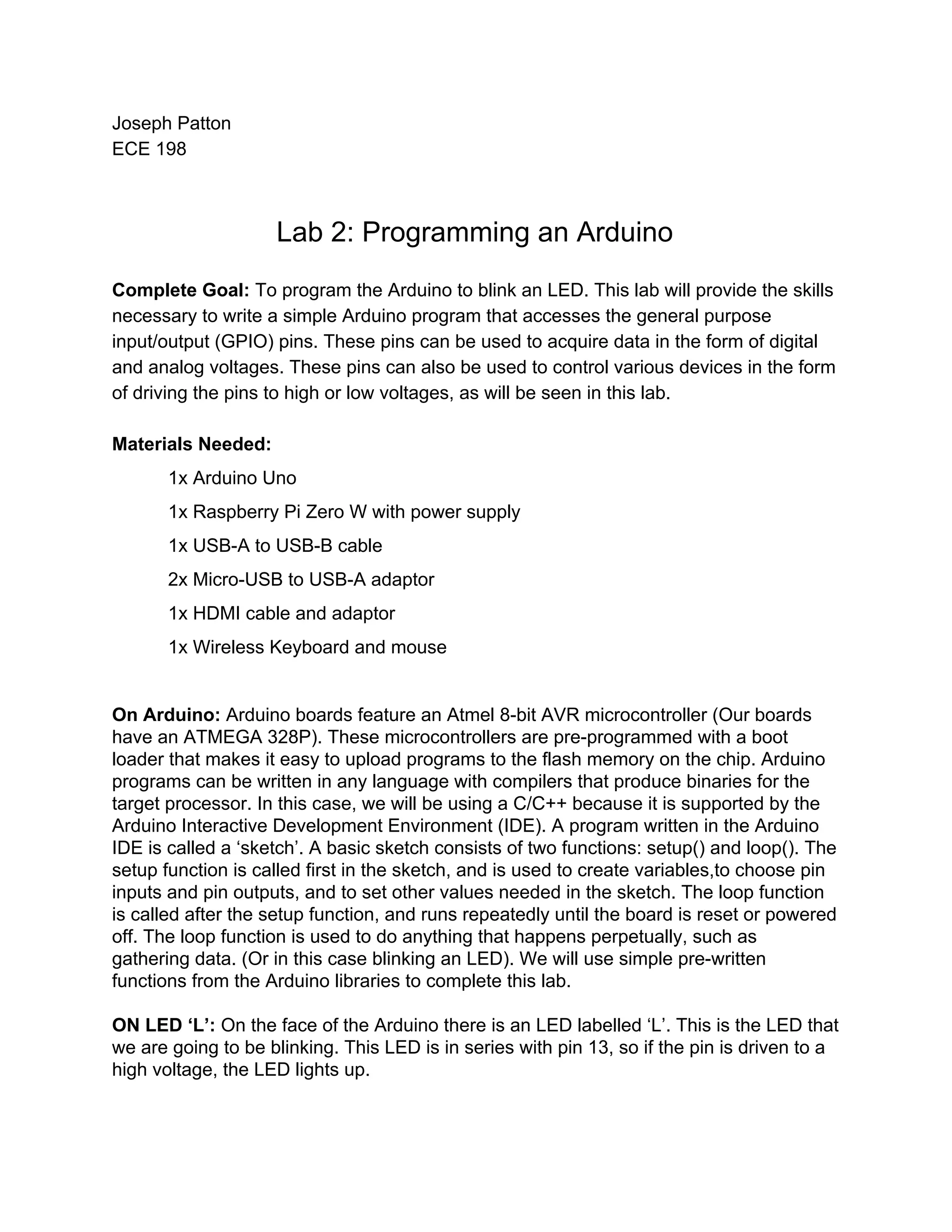
Joseph Patton ECE 198 Lab 2: Programming an Arduino Complete Goal: ​To program the Arduino to blink an LED. This lab will provide the skills necessary to write a simple Arduino program that accesses the general purpose input/output (GPIO) pins. These pins can be used to acquire data in the form of digital and analog voltages. These pins can also be used to control various devices in the form of driving the pins to high or low voltages, as will be seen in this lab. Materials Needed: 1x Arduino Uno 1x Raspberry Pi Zero W with power supply 1x USB-A to USB-B cable 2x Micro-USB to USB-A adaptor 1x HDMI cable and adaptor 1x Wireless Keyboard and mouse On Arduino: ​Arduino boards feature an Atmel 8-bit AVR microcontroller (Our boards have an ATMEGA 328P). These microcontrollers are pre-programmed with a boot loader that makes it easy to upload programs to the flash memory on the chip. Arduino programs can be written in any language with compilers that produce binaries for the target processor. In this case, we will be using a C/C++ because it is supported by the Arduino Interactive Development Environment (IDE). A program written in the Arduino IDE is called a ‘sketch’. A basic sketch consists of two functions: setup() and loop(). The setup function is called first in the sketch, and is used to create variables,to choose pin inputs and pin outputs, and to set other values needed in the sketch. The loop function is called after the setup function, and runs repeatedly until the board is reset or powered off. The loop function is used to do anything that happens perpetually, such as gathering data. (Or in this case blinking an LED). We will use simple pre-written functions from the Arduino libraries to complete this lab. ON LED ‘L’: ​On the face of the Arduino there is an LED labelled ‘L’. This is the LED that we are going to be blinking. This LED is in series with pin 13, so if the pin is driven to a high voltage, the LED lights up.
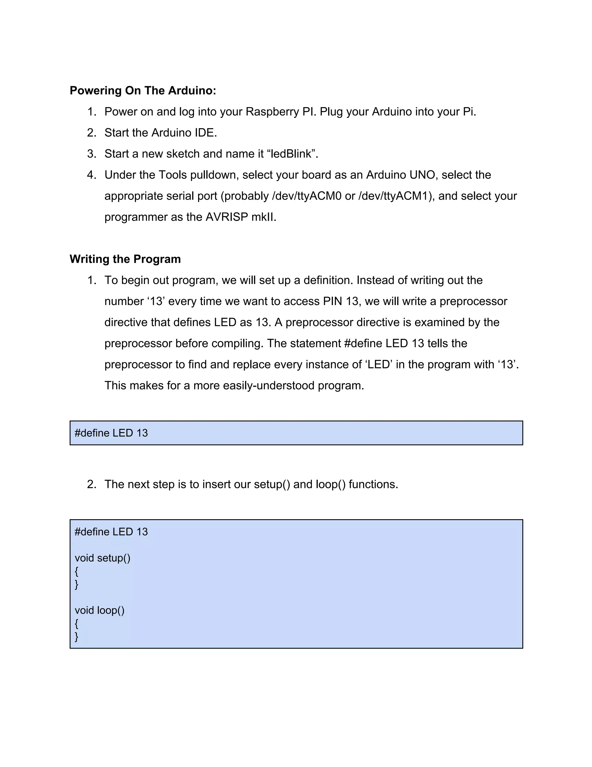
Powering On The Arduino: 1. Power on and log into your Raspberry PI. Plug your Arduino into your Pi. 2. Start the Arduino IDE. 3. Start a new sketch and name it “ledBlink”. 4. Under the Tools pulldown, select your board as an Arduino UNO, select the appropriate serial port (probably /dev/ttyACM0 or /dev/ttyACM1), and select your programmer as the AVRISP mkII. Writing the Program 1. To begin out program, we will set up a definition. Instead of writing out the number ‘13’ every time we want to access PIN 13, we will write a preprocessor directive that defines LED as 13. A preprocessor directive is examined by the preprocessor before compiling. The statement #define LED 13 tells the preprocessor to find and replace every instance of ‘LED’ in the program with ‘13’. This makes for a more easily-understood program. #define LED 13 2. The next step is to insert our setup() and loop() functions. #define LED 13 void setup() { } void loop() { }
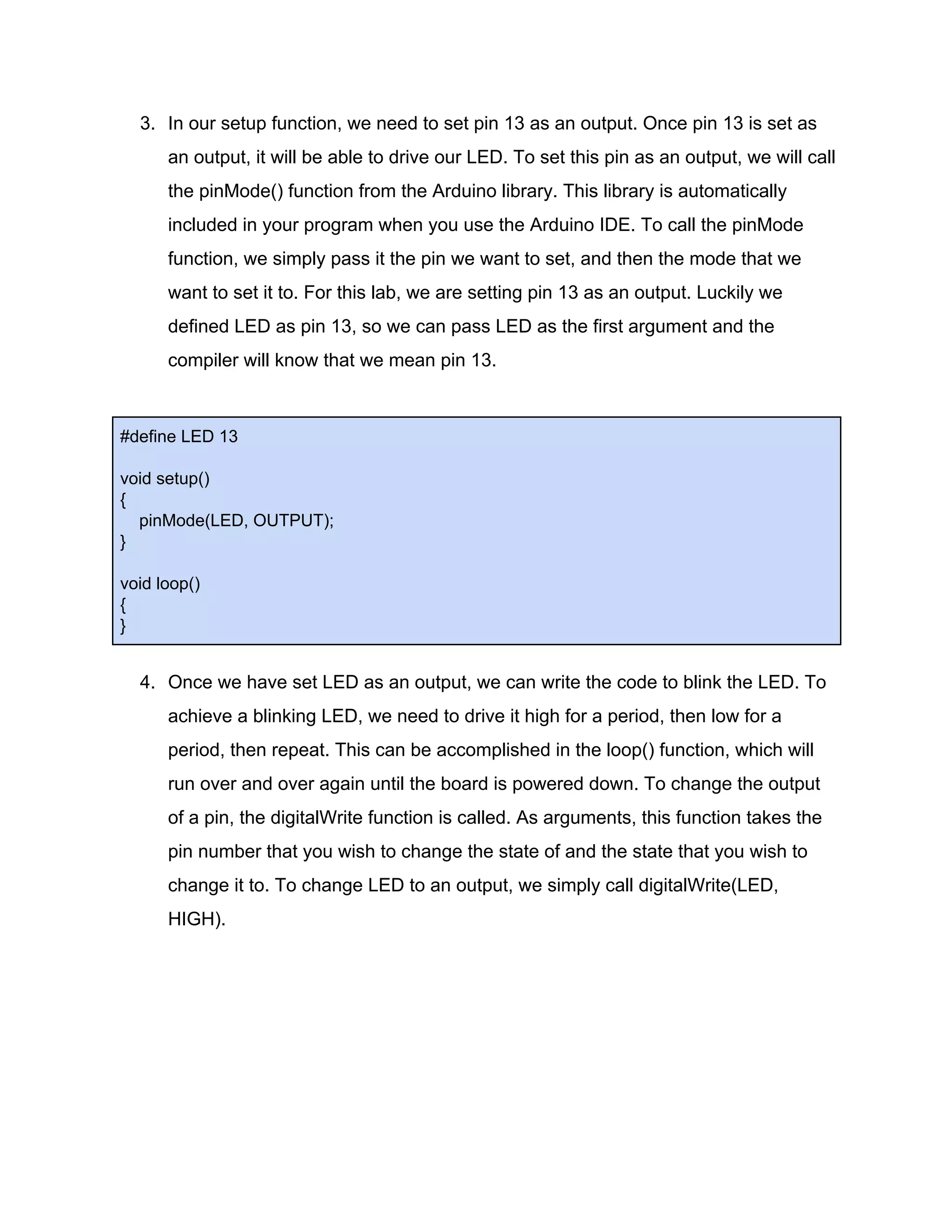
3. In our setup function, we need to set pin 13 as an output. Once pin 13 is set as an output, it will be able to drive our LED. To set this pin as an output, we will call the pinMode() function from the Arduino library. This library is automatically included in your program when you use the Arduino IDE. To call the pinMode function, we simply pass it the pin we want to set, and then the mode that we want to set it to. For this lab, we are setting pin 13 as an output. Luckily we defined LED as pin 13, so we can pass LED as the first argument and the compiler will know that we mean pin 13. #define LED 13 void setup() { pinMode(LED, OUTPUT); } void loop() { } 4. Once we have set LED as an output, we can write the code to blink the LED. To achieve a blinking LED, we need to drive it high for a period, then low for a period, then repeat. This can be accomplished in the loop() function, which will run over and over again until the board is powered down. To change the output of a pin, the digitalWrite function is called. As arguments, this function takes the pin number that you wish to change the state of and the state that you wish to change it to. To change LED to an output, we simply call digitalWrite(LED, HIGH).
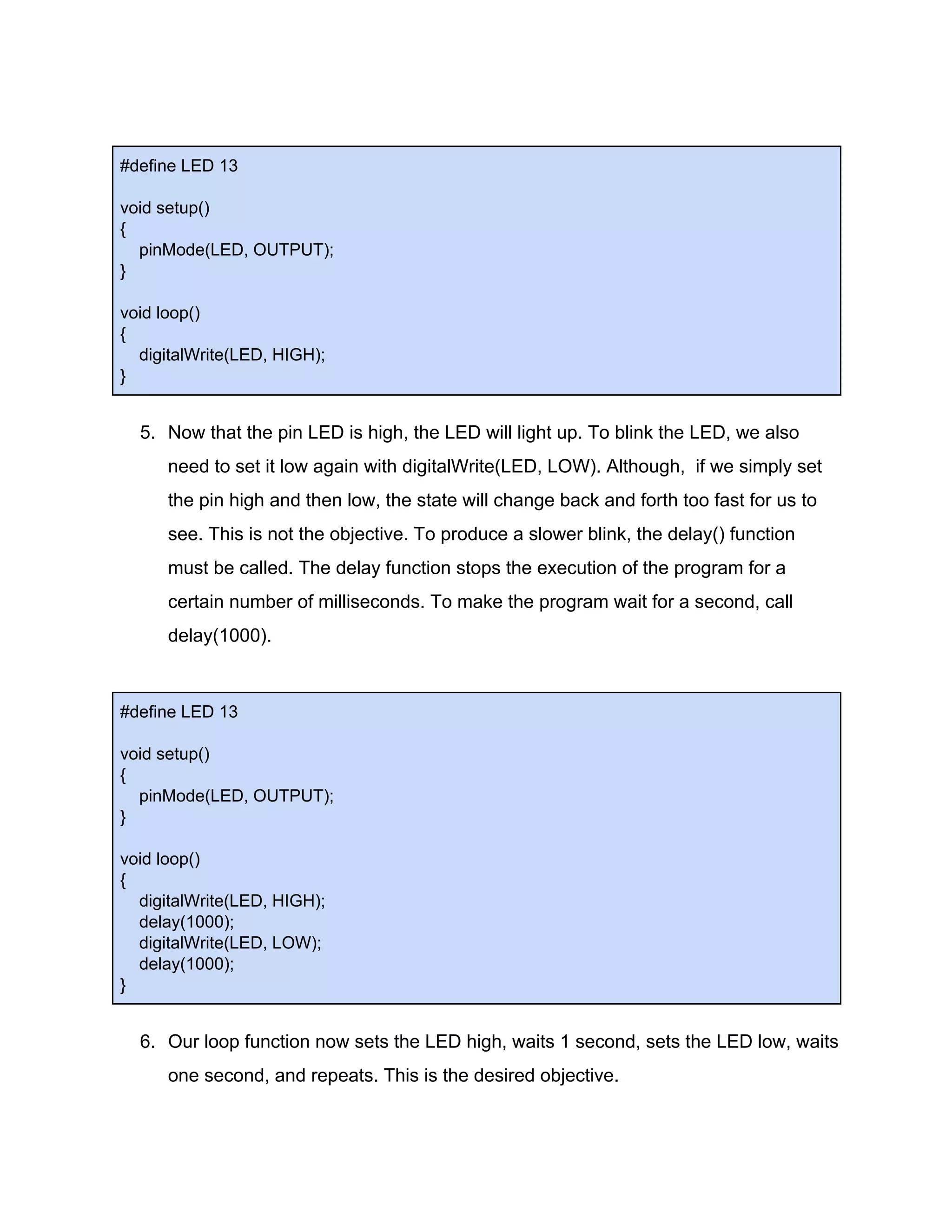
#define LED 13 void setup() { pinMode(LED, OUTPUT); } void loop() { digitalWrite(LED, HIGH); } 5. Now that the pin LED is high, the LED will light up. To blink the LED, we also need to set it low again with digitalWrite(LED, LOW). Although, if we simply set the pin high and then low, the state will change back and forth too fast for us to see. This is not the objective. To produce a slower blink, the delay() function must be called. The delay function stops the execution of the program for a certain number of milliseconds. To make the program wait for a second, call delay(1000). #define LED 13 void setup() { pinMode(LED, OUTPUT); } void loop() { digitalWrite(LED, HIGH); delay(1000); digitalWrite(LED, LOW); delay(1000); } 6. Our loop function now sets the LED high, waits 1 second, sets the LED low, waits one second, and repeats. This is the desired objective.
Programming the Board: 1. First save the program with Ctrl + S. To compile the program, press Ctrl + R, or click the checkmark button. To upload the sketch, press Ctrl + U, or press the forward arrow button. If both of these succeed, the program should be uploaded to your board, and LED ‘L’ should be blinking.

Lab 2_ Programming an Arduino.pdf

  • 1.
    Joseph Patton ECE 198 Lab2: Programming an Arduino Complete Goal: ​To program the Arduino to blink an LED. This lab will provide the skills necessary to write a simple Arduino program that accesses the general purpose input/output (GPIO) pins. These pins can be used to acquire data in the form of digital and analog voltages. These pins can also be used to control various devices in the form of driving the pins to high or low voltages, as will be seen in this lab. Materials Needed: 1x Arduino Uno 1x Raspberry Pi Zero W with power supply 1x USB-A to USB-B cable 2x Micro-USB to USB-A adaptor 1x HDMI cable and adaptor 1x Wireless Keyboard and mouse On Arduino: ​Arduino boards feature an Atmel 8-bit AVR microcontroller (Our boards have an ATMEGA 328P). These microcontrollers are pre-programmed with a boot loader that makes it easy to upload programs to the flash memory on the chip. Arduino programs can be written in any language with compilers that produce binaries for the target processor. In this case, we will be using a C/C++ because it is supported by the Arduino Interactive Development Environment (IDE). A program written in the Arduino IDE is called a ‘sketch’. A basic sketch consists of two functions: setup() and loop(). The setup function is called first in the sketch, and is used to create variables,to choose pin inputs and pin outputs, and to set other values needed in the sketch. The loop function is called after the setup function, and runs repeatedly until the board is reset or powered off. The loop function is used to do anything that happens perpetually, such as gathering data. (Or in this case blinking an LED). We will use simple pre-written functions from the Arduino libraries to complete this lab. ON LED ‘L’: ​On the face of the Arduino there is an LED labelled ‘L’. This is the LED that we are going to be blinking. This LED is in series with pin 13, so if the pin is driven to a high voltage, the LED lights up.
  • 2.
    Powering On TheArduino: 1. Power on and log into your Raspberry PI. Plug your Arduino into your Pi. 2. Start the Arduino IDE. 3. Start a new sketch and name it “ledBlink”. 4. Under the Tools pulldown, select your board as an Arduino UNO, select the appropriate serial port (probably /dev/ttyACM0 or /dev/ttyACM1), and select your programmer as the AVRISP mkII. Writing the Program 1. To begin out program, we will set up a definition. Instead of writing out the number ‘13’ every time we want to access PIN 13, we will write a preprocessor directive that defines LED as 13. A preprocessor directive is examined by the preprocessor before compiling. The statement #define LED 13 tells the preprocessor to find and replace every instance of ‘LED’ in the program with ‘13’. This makes for a more easily-understood program. #define LED 13 2. The next step is to insert our setup() and loop() functions. #define LED 13 void setup() { } void loop() { }
  • 3.
    3. In oursetup function, we need to set pin 13 as an output. Once pin 13 is set as an output, it will be able to drive our LED. To set this pin as an output, we will call the pinMode() function from the Arduino library. This library is automatically included in your program when you use the Arduino IDE. To call the pinMode function, we simply pass it the pin we want to set, and then the mode that we want to set it to. For this lab, we are setting pin 13 as an output. Luckily we defined LED as pin 13, so we can pass LED as the first argument and the compiler will know that we mean pin 13. #define LED 13 void setup() { pinMode(LED, OUTPUT); } void loop() { } 4. Once we have set LED as an output, we can write the code to blink the LED. To achieve a blinking LED, we need to drive it high for a period, then low for a period, then repeat. This can be accomplished in the loop() function, which will run over and over again until the board is powered down. To change the output of a pin, the digitalWrite function is called. As arguments, this function takes the pin number that you wish to change the state of and the state that you wish to change it to. To change LED to an output, we simply call digitalWrite(LED, HIGH).
  • 4.
    #define LED 13 voidsetup() { pinMode(LED, OUTPUT); } void loop() { digitalWrite(LED, HIGH); } 5. Now that the pin LED is high, the LED will light up. To blink the LED, we also need to set it low again with digitalWrite(LED, LOW). Although, if we simply set the pin high and then low, the state will change back and forth too fast for us to see. This is not the objective. To produce a slower blink, the delay() function must be called. The delay function stops the execution of the program for a certain number of milliseconds. To make the program wait for a second, call delay(1000). #define LED 13 void setup() { pinMode(LED, OUTPUT); } void loop() { digitalWrite(LED, HIGH); delay(1000); digitalWrite(LED, LOW); delay(1000); } 6. Our loop function now sets the LED high, waits 1 second, sets the LED low, waits one second, and repeats. This is the desired objective.
  • 5.
    Programming the Board: 1.First save the program with Ctrl + S. To compile the program, press Ctrl + R, or click the checkmark button. To upload the sketch, press Ctrl + U, or press the forward arrow button. If both of these succeed, the program should be uploaded to your board, and LED ‘L’ should be blinking.