Objectives 目标 By theend of the lesson, students will be able to: 1. Understand the basic function of an Arduino board and associated components. 2. Use Tinkercad to build a virtual circuit with an LED. 3. Write basic Arduino code to control the LED. 在课程结束时,学生将能够: 1. 了解 Arduino 板和相关组件 的基本功能。 2. 使用 Tinkercad 构建带有 LED 的虚拟电路。 3. 编写基本的 Arduino 代码来 控制 LED 。
3.
What is Arduino? -Arduino is a microcontroller board that can be programmed to control different electrical components like LEDs, motors, sensors, etc. - Microcontroller: A small computer inside the Arduino that processes commands from the code you write. - Digital Input/Output (I/O) Pins: These pins are used to connect external components like LEDs, sensors, etc. Pins can either output voltage (turn something on, like an LED) or input voltage (read something, like a button press). Arduino 是一个微控制器板,可以对 其进行编程以控制不同的电气组件, 如 LED 、电机、传感器等。 微控制器: Arduino 内部的一台小 型计算机,用于处理您编写的代码中 的命令。 - 数字输入 / 输出 ( I/O ) 引脚:这 些引脚用于连接 LED 、传感器等外 部组件。引脚可以输出电压(打开 某个东西,如 LED )或输入电压 (读取某个东西,如按下按钮)。
4.
Components and TheirRoles 1. Arduino Uno: - The main board we will use to control the LED. - The pins on the Arduino board allow us to connect different components. We’ll be using pin 13 for output. 1. Arduino Uno : - 我们将用于控制 LED 的主板。 - Arduino 板上的引脚允许我们连接不同的组件。我们将使用引脚 13 进行输出。
5.
Components and TheirRoles 2. Breadboard: - A tool for building temporary circuits without soldering. - The breadboard has two sets of holes for components; we use the horizontal rows to connect different components. - Two vertical rails are usually reserved for power (+) and ground (GND). 2. 面包板: - 无需焊接即可构建临时电路的工具。 - 试验板有两组组件孔 ; 我们使用水平行来连接不同的组件。 - 两个垂直导轨通常保留用于电源 ( + ) 和接地 ( GND )。
6.
Components and TheirRoles 3. LED (Light Emitting Diode): - A small light that turns on when electricity flows through it. - Important: The LED has two legs: - Anode (longer leg): Connects to the positive (power) side. - Cathode (shorter leg): Connects to the ground (negative). 3. LED (发光二极管): - 当电流流过时会亮起的小灯。 - 重要提示: LED 有两个脚管: - 阳极(较长的腿):连接到正极(电源)侧。 - 阴极(较短的腿):连接到地面(负极)。
7.
Components and TheirRoles 4. Resistor (220Ω): - Limits the current flowing through the LED to prevent it from burning out. 4. 电阻 ( 220Ω ): - 限制流经 LED 的电流,以防止其烧坏。 5. Wires: - Used to connect components together on the breadboard. 5. 电线: - 用于将试验板上的组件连接在一起。
8.
Materials - Access toTinkercad (create accounts prior to the lesson) - Basic components: Arduino Uno, Breadboard, LED, Resistor (220Ω), and wires (virtual in Tinkercad) - 访问 Tinkercad (在课前创建 帐户) - 基本组件: Arduino Uno 、面 包板、 LED 、电阻器 ( 220Ω ) 和电线(在 Tinkercad 中虚拟)
9.
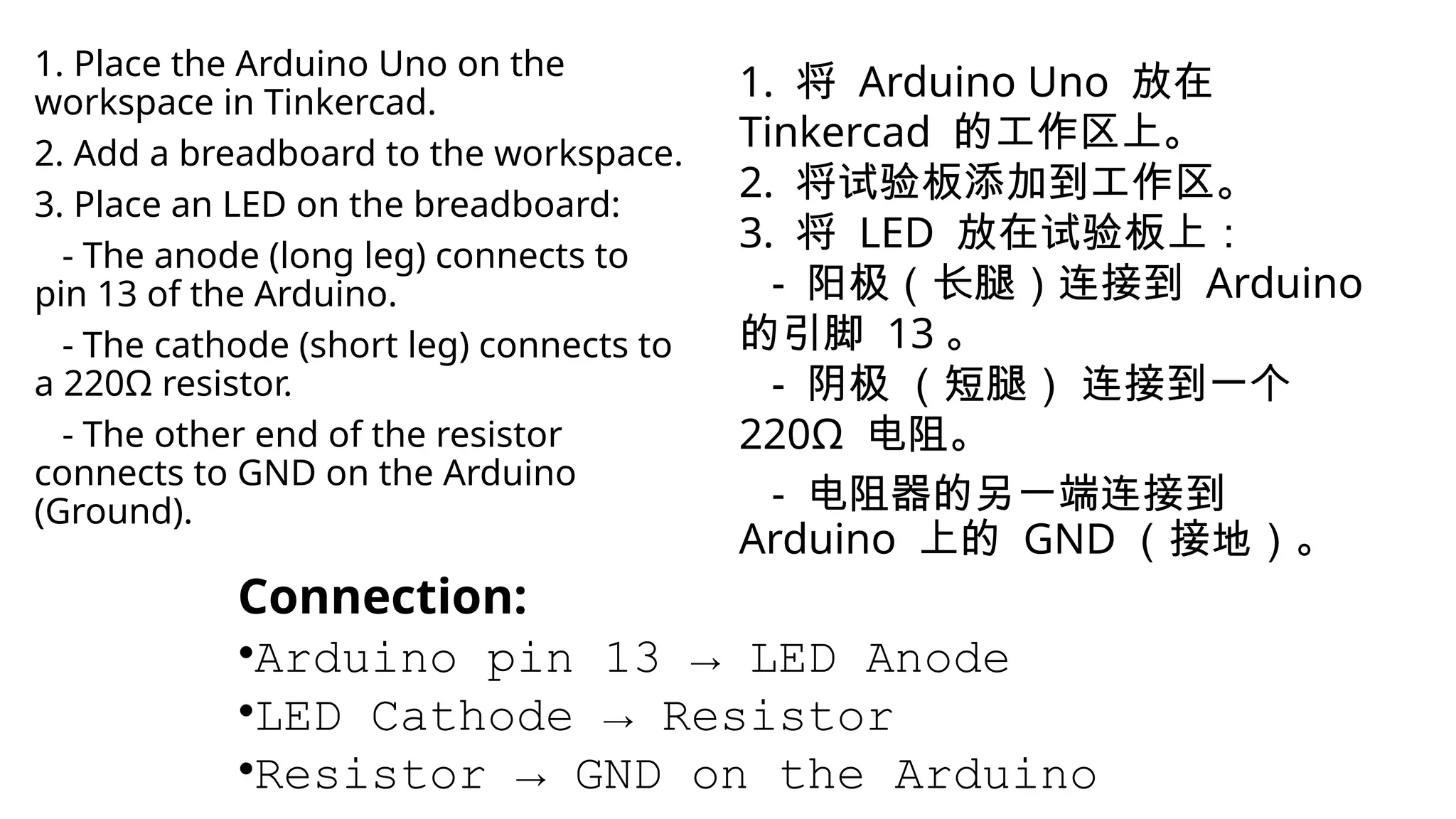
1. Place theArduino Uno on the workspace in Tinkercad. 2. Add a breadboard to the workspace. 3. Place an LED on the breadboard: - The anode (long leg) connects to pin 13 of the Arduino. - The cathode (short leg) connects to a 220Ω resistor. - The other end of the resistor connects to GND on the Arduino (Ground). Connection: •Arduino pin 13 → LED Anode •LED Cathode → Resistor •Resistor → GND on the Arduino 1. 将 Arduino Uno 放在 Tinkercad 的工作区上。 2. 将试验板添加到工作区。 3. 将 LED 放在试验板上: - 阳极(长腿)连接到 Arduino 的引脚 13 。 - 阴极 (短腿) 连接到一个 220Ω 电阻。 - 电阻器的另一端连接到 Arduino 上的 GND (接地)。
10.
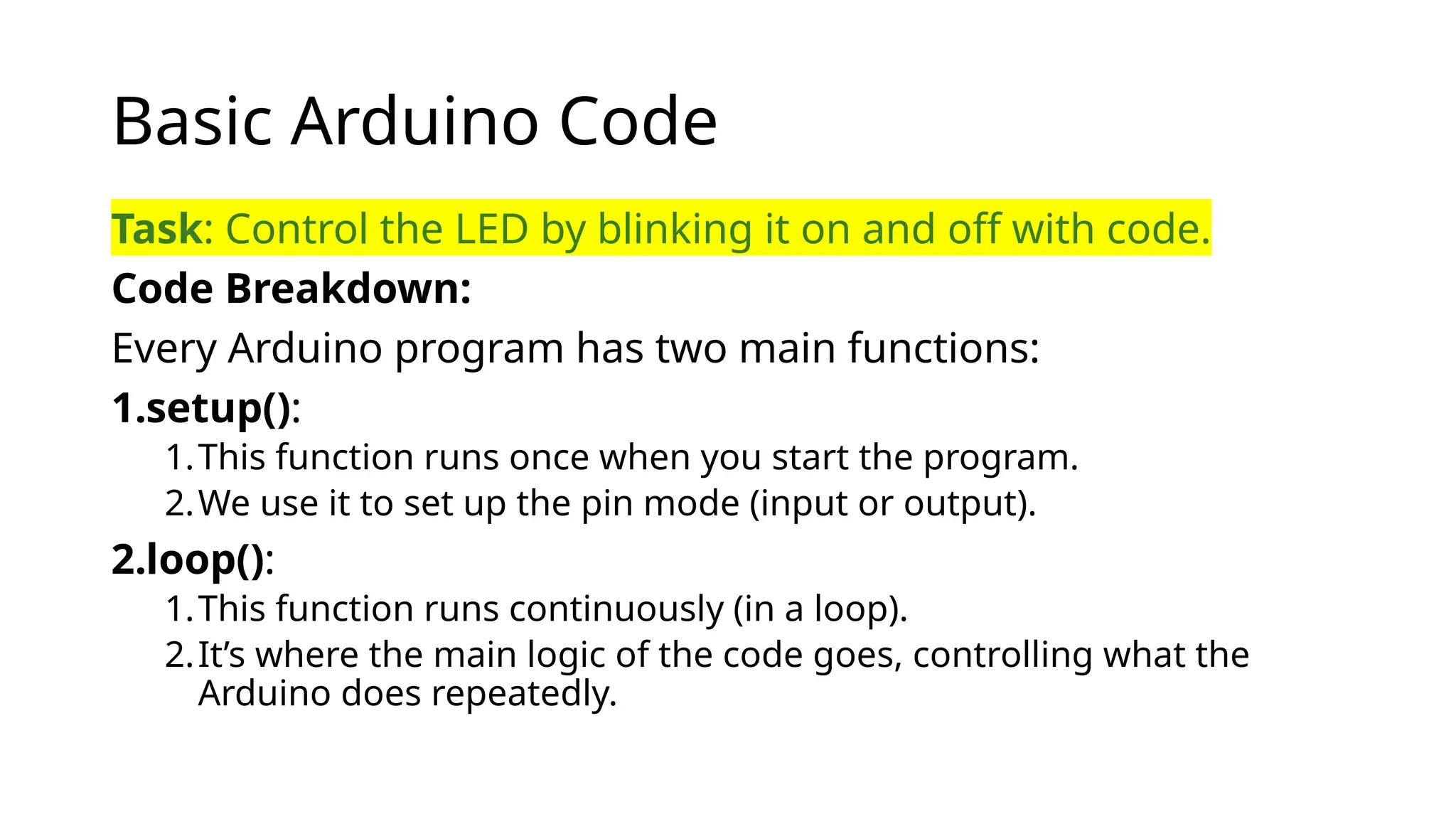
Basic Arduino Code Task:Control the LED by blinking it on and off with code. Code Breakdown: Every Arduino program has two main functions: 1.setup(): 1.This function runs once when you start the program. 2.We use it to set up the pin mode (input or output). 2.loop(): 1.This function runs continuously (in a loop). 2.It’s where the main logic of the code goes, controlling what the Arduino does repeatedly.
11.
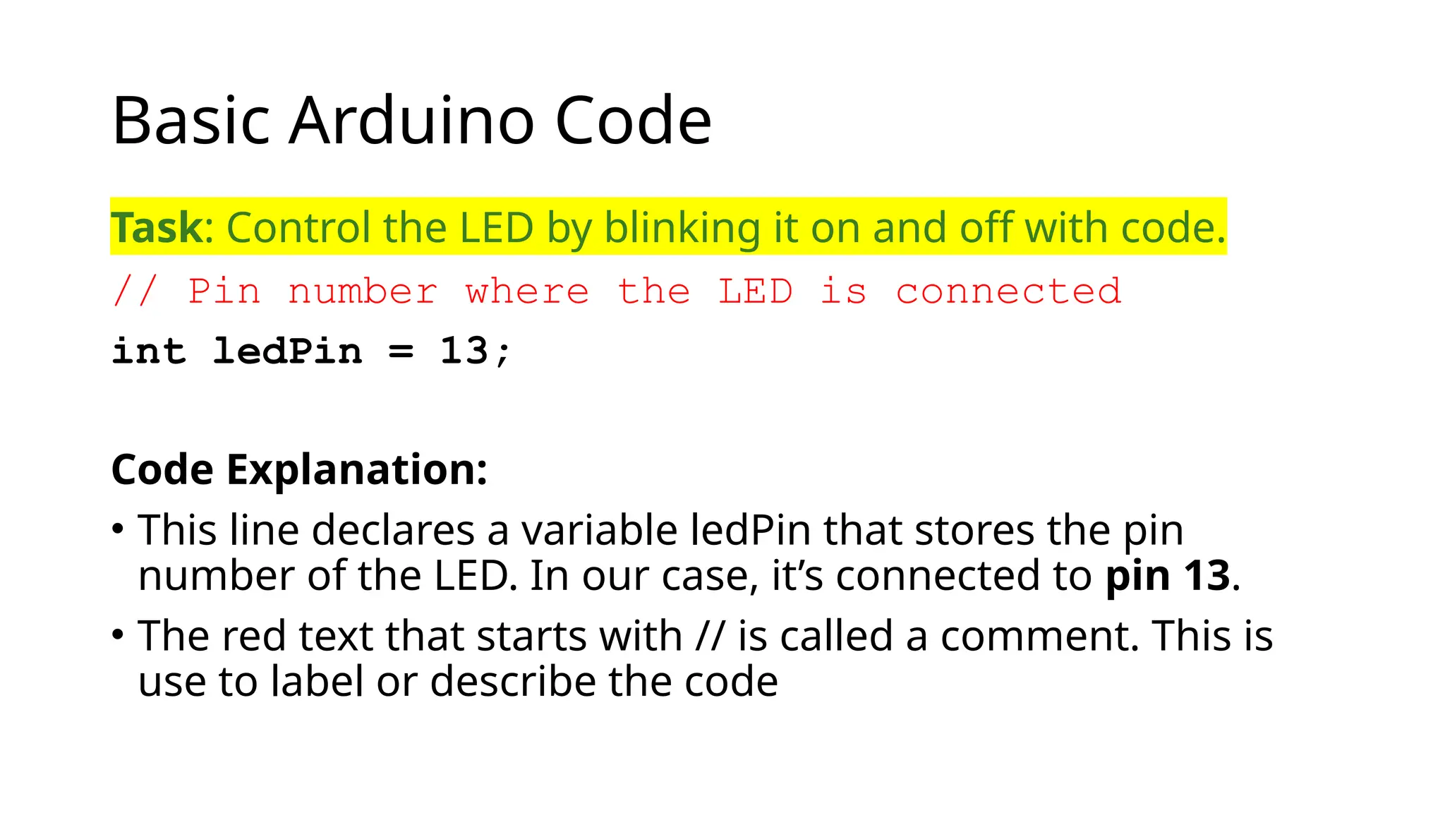
Basic Arduino Code Task:Control the LED by blinking it on and off with code. // Pin number where the LED is connected int ledPin = 13; Code Explanation: • This line declares a variable ledPin that stores the pin number of the LED. In our case, it’s connected to pin 13. • The red text that starts with // is called a comment. This is use to label or describe the code
12.
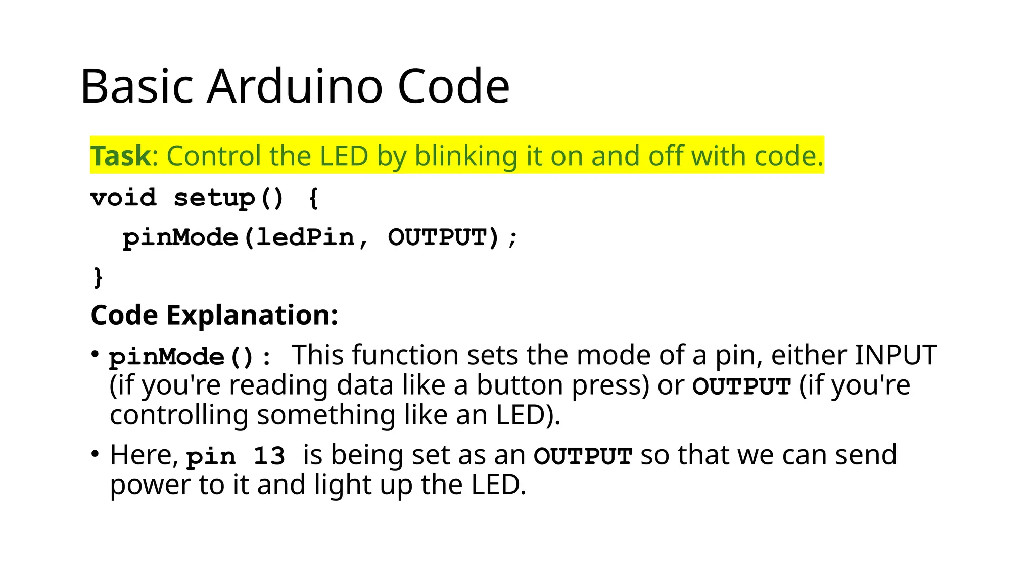
Basic Arduino Code Task:Control the LED by blinking it on and off with code. void setup() { pinMode(ledPin, OUTPUT); } Code Explanation: • pinMode(): This function sets the mode of a pin, either INPUT (if you're reading data like a button press) or OUTPUT (if you're controlling something like an LED). • Here, pin 13 is being set as an OUTPUT so that we can send power to it and light up the LED.
13.
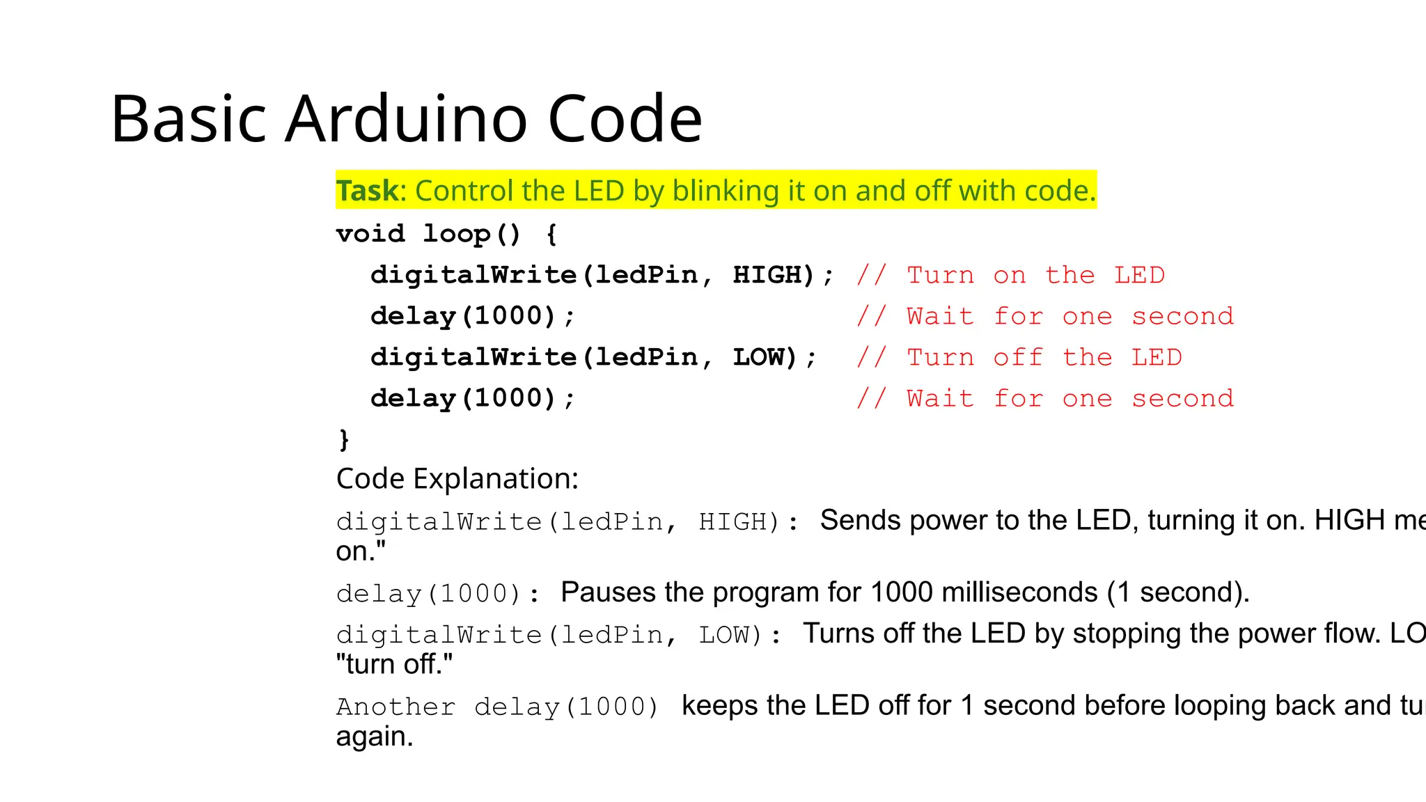
Basic Arduino Code Task:Control the LED by blinking it on and off with code. void loop() { digitalWrite(ledPin, HIGH); // Turn on the LED delay(1000); // Wait for one second digitalWrite(ledPin, LOW); // Turn off the LED delay(1000); // Wait for one second } Code Explanation: digitalWrite(ledPin, HIGH): Sends power to the LED, turning it on. HIGH me on." delay(1000): Pauses the program for 1000 milliseconds (1 second). digitalWrite(ledPin, LOW): Turns off the LED by stopping the power flow. LO "turn off." Another delay(1000) keeps the LED off for 1 second before looping back and tur again.
14.
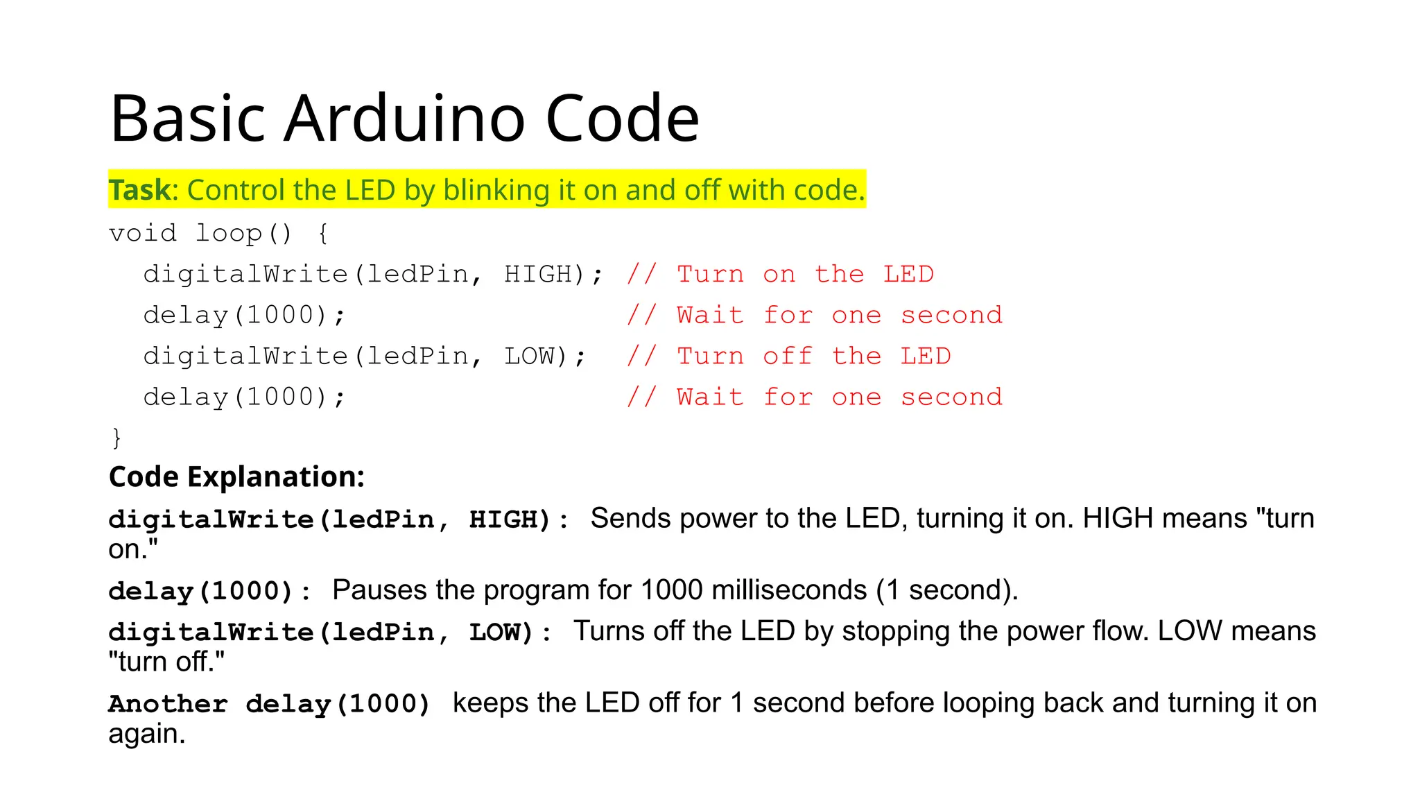
Basic Arduino Code Task:Control the LED by blinking it on and off with code. void loop() { digitalWrite(ledPin, HIGH); // Turn on the LED delay(1000); // Wait for one second digitalWrite(ledPin, LOW); // Turn off the LED delay(1000); // Wait for one second } Code Explanation: digitalWrite(ledPin, HIGH): Sends power to the LED, turning it on. HIGH means "turn on." delay(1000): Pauses the program for 1000 milliseconds (1 second). digitalWrite(ledPin, LOW): Turns off the LED by stopping the power flow. LOW means "turn off." Another delay(1000) keeps the LED off for 1 second before looping back and turning it on again.
15.
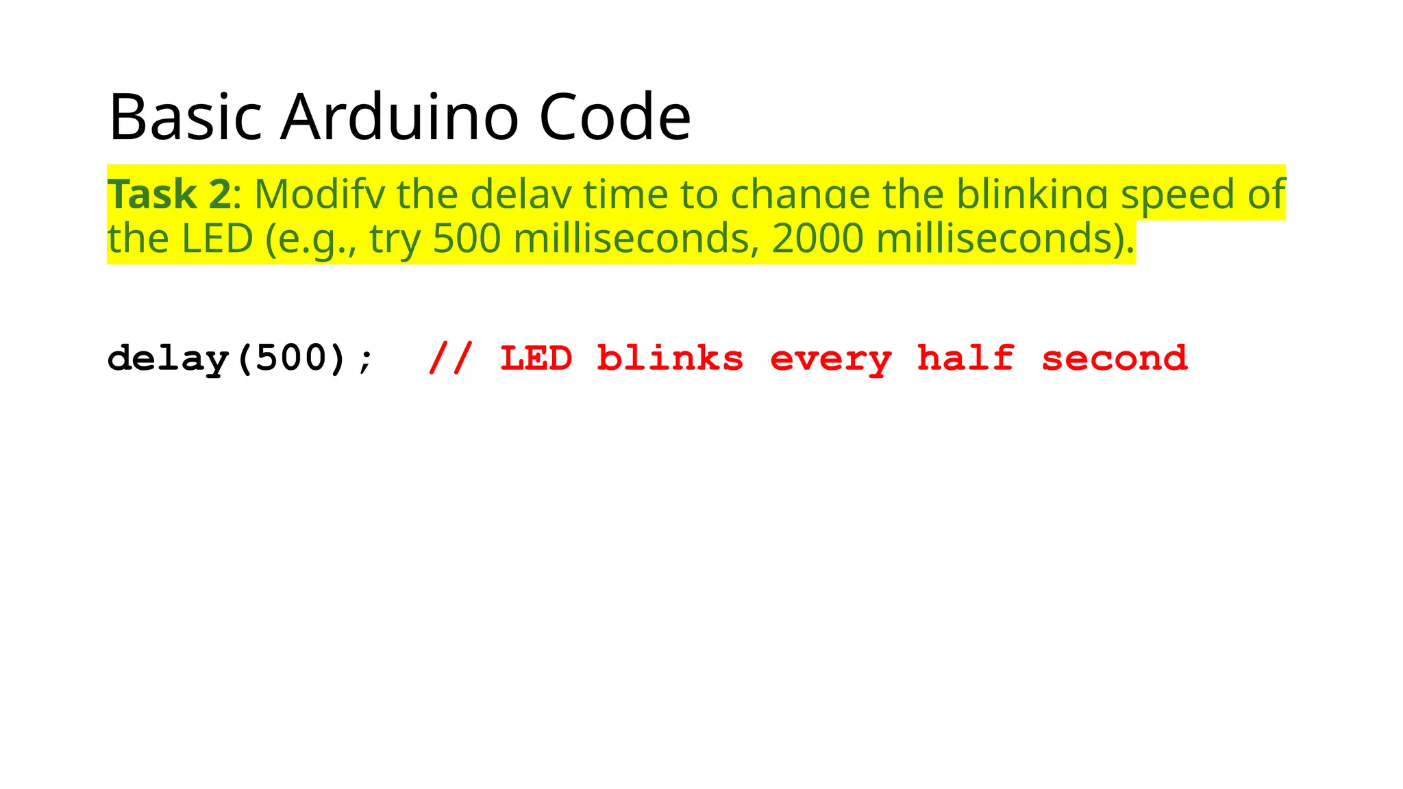
Basic Arduino Code Task2: Modify the delay time to change the blinking speed of the LED (e.g., try 500 milliseconds, 2000 milliseconds). delay(500); // LED blinks every half second
16.
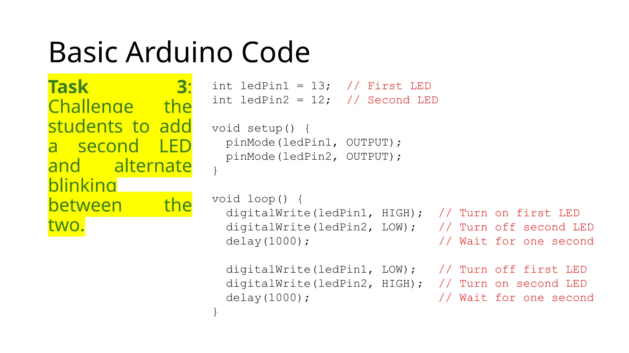
Basic Arduino Code Task3: Challenge the students to add a second LED and alternate blinking between the two. int ledPin1 = 13; // First LED int ledPin2 = 12; // Second LED void setup() { pinMode(ledPin1, OUTPUT); pinMode(ledPin2, OUTPUT); } void loop() { digitalWrite(ledPin1, HIGH); // Turn on first LED digitalWrite(ledPin2, LOW); // Turn off second LED delay(1000); // Wait for one second digitalWrite(ledPin1, LOW); // Turn off first LED digitalWrite(ledPin2, HIGH); // Turn on second LED delay(1000); // Wait for one second }