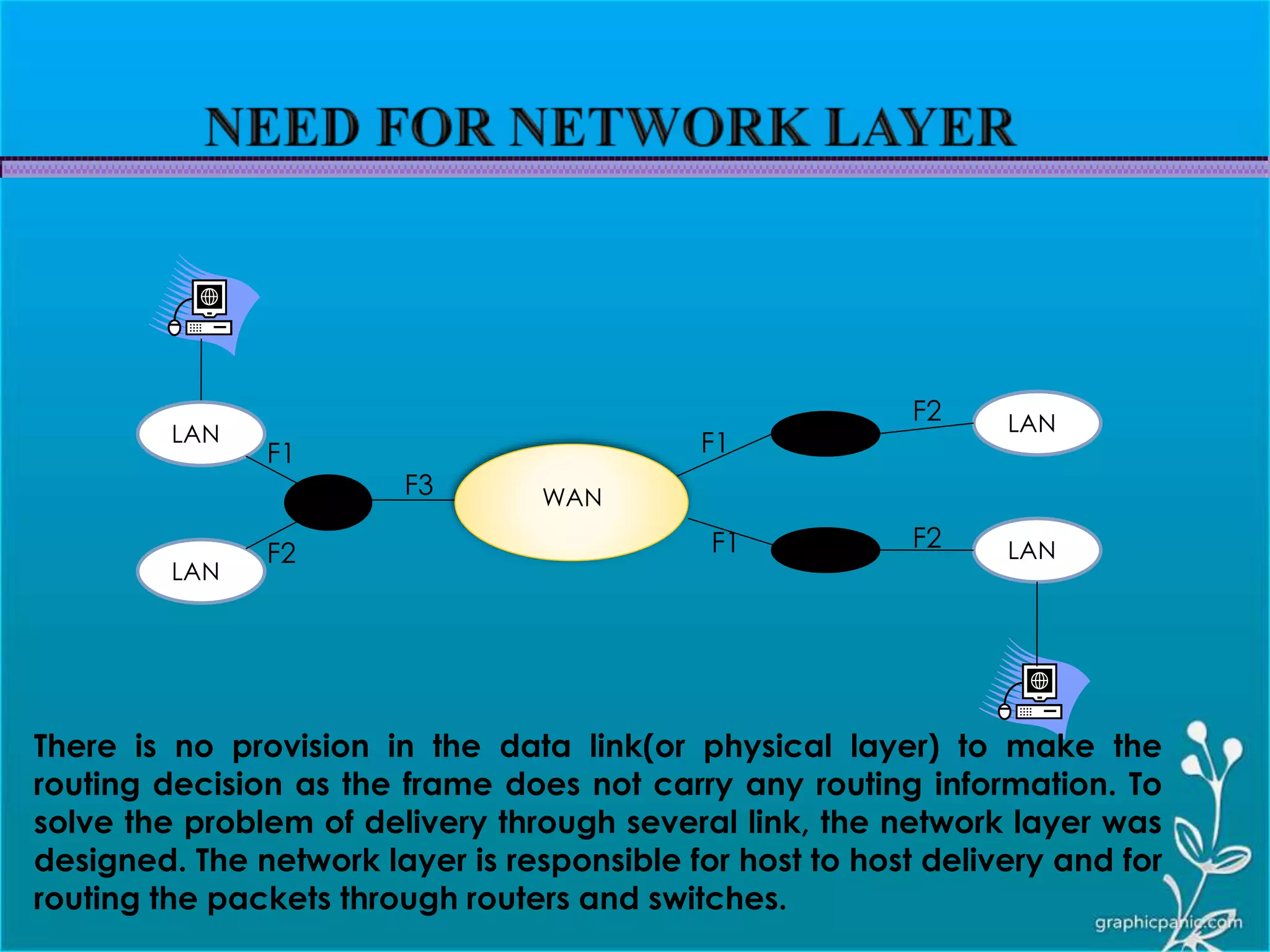
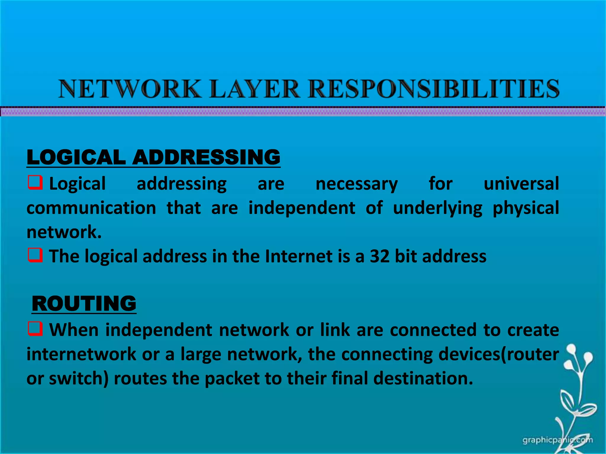
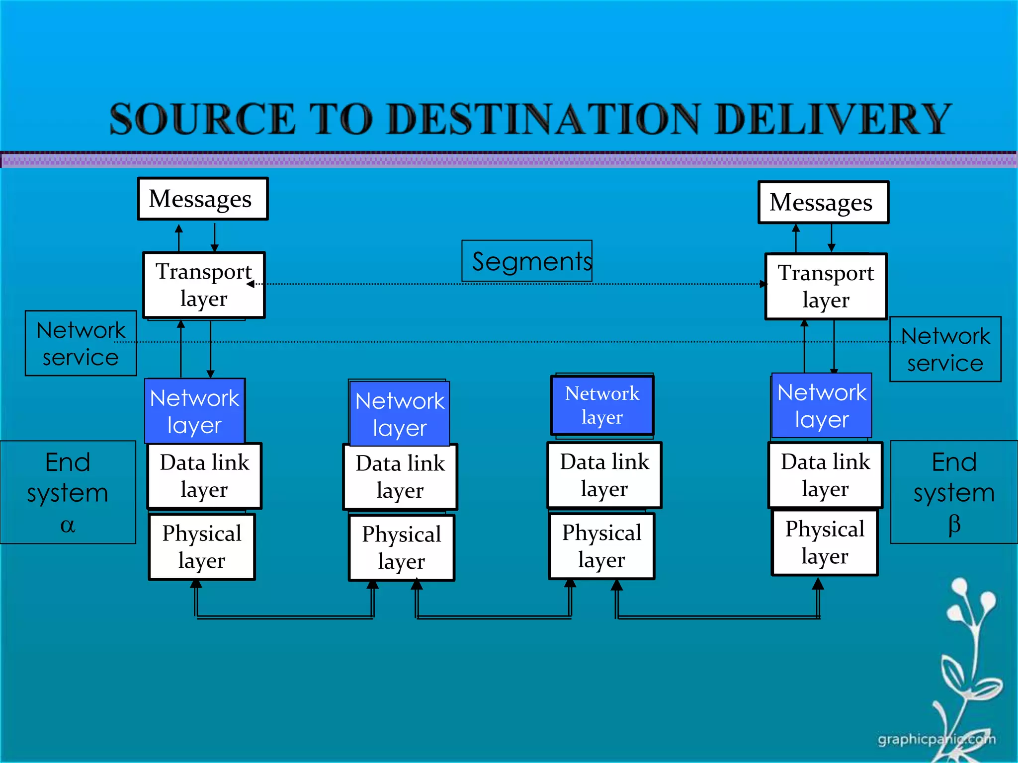
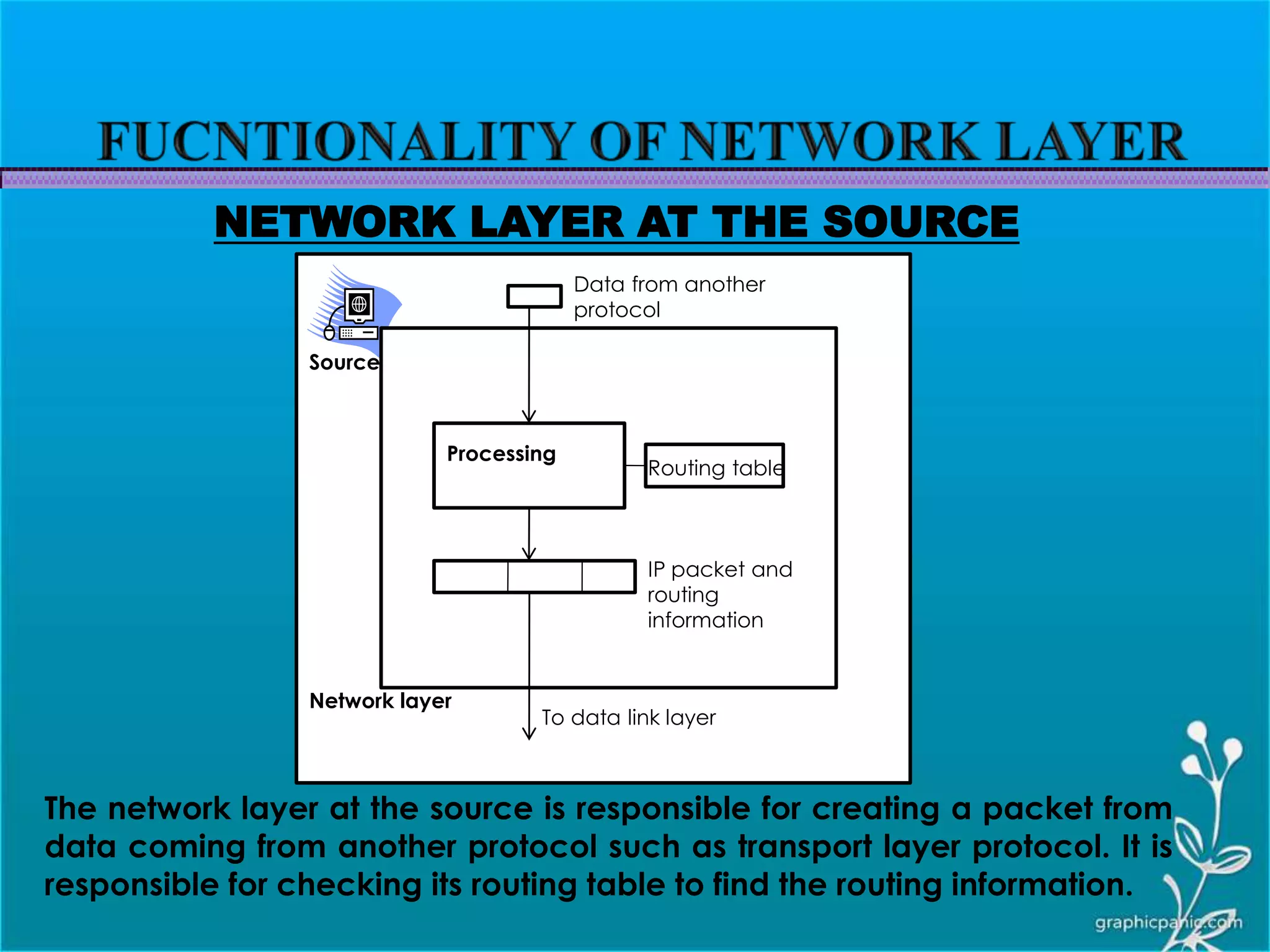
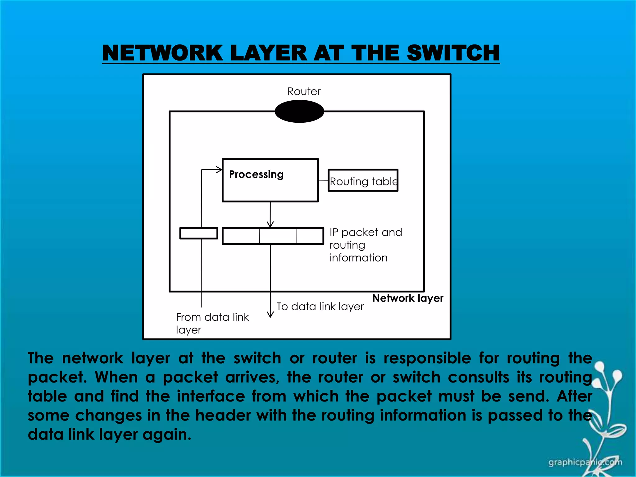
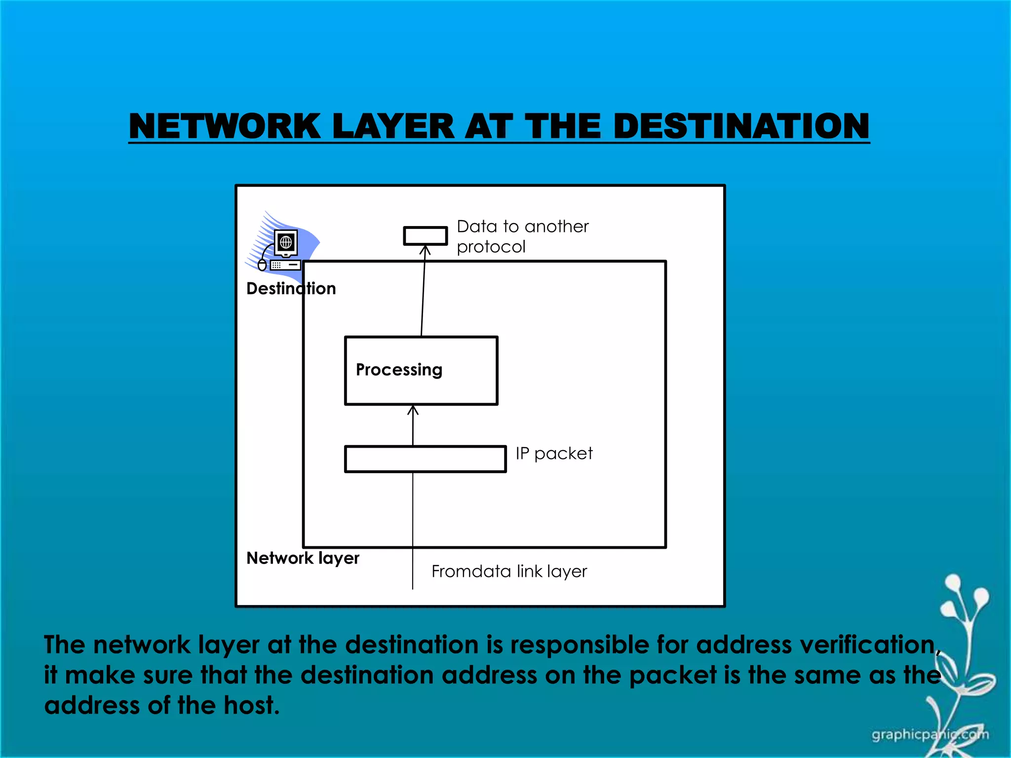
 Network layer is responsible for source to destination delivery of the packets.  The network layer must know the topology of the subnet and choose appropriate paths through it.  When source and destination are in different networks, the network layer (IP) must deal with these differences.  If two system are connected to the same link, there is usually no need for a network layer.
H3 H3Data Data From Transport layer From data link layer To Transport layer To data link layer
WAN LAN LAN LAN LAN F1 F1 F3 F2 F1 F2 F2 There is no provision in the data link(or physical layer) to make the routing decision as the frame does not carry any routing information. To solve the problem of delivery through several link, the network layer was designed. The network layer is responsible for host to host delivery and for routing the packets through routers and switches.
LOGICAL ADDRESSING  Logical addressing are necessary for universal communication that are independent of underlying physical network.  The logical address in the Internet is a 32 bit address ROUTING  When independent network or link are connected to create internetwork or a large network, the connecting devices(router or switch) routes the packet to their final destination.
Physical layer Data link layer Physical layer Data link layer End system a Network layer Physical layer Data link layer Physical layer Data link layer Transport layer Transport layer Messages Messages Segments End system b Network service Network service Network layer Network layer Network layer
Routing table IP packet and routing information To data link layer Data from another protocol Processing Network layer The network layer at the source is responsible for creating a packet from data coming from another protocol such as transport layer protocol. It is responsible for checking its routing table to find the routing information. NETWORK LAYER AT THE SOURCE Source
Routing table IP packet and routing information To data link layer Processing Network layer From data link layer Router The network layer at the switch or router is responsible for routing the packet. When a packet arrives, the router or switch consults its routing table and find the interface from which the packet must be send. After some changes in the header with the routing information is passed to the data link layer again. NETWORK LAYER AT THE SWITCH
IP packet Fromdata link layer Data to another protocol Processing Network layer The network layer at the destination is responsible for address verification, it make sure that the destination address on the packet is the same as the address of the host. NETWORK LAYER AT THE DESTINATION Destination
At the network layer, TCP/IP supports the Internetworking Protocol i.e. IP with four supporting protocol: ARP, RARP, ICMP, and IGMP. LOGICAL ADDRESSING  Transmission mechanism used by the TCP/IP protocol.  It is unreliable and connectionless protocol.  It does not provide error checking or tracking.  IP transport data in packets called datagram.  IP does not keep track of the routes and has no facility of reordering datagram. ADDRESS RESOLUTION PROTOCOL  Used to associate a logical address with a physical address.  ARP is used to find the physical address of the node when its internet address is known.
REVERSE ADDRESS RESOLUTION PROTOCOL  Its allows a host to discover its Internet address when its knows only its physical address.  It is used when a computer is connected to a network for the first time. INTERNET CONTROL MESSAGE PROTOCOL  ICMP is used by hosts or gateways to send notification of datagram problems back to the sender.  Its send query and error reporting messages. INTERNET GROUP MESSAGE PROTOCOL  IGMP is used to facilitate the simultaneous transmission of a message to a group of recipients.
 The internet at the network layer is a packet switched network.  Packet switching uses either the virtual circuit approach or the datagram approach.  The internet is chosen the datagram approach to switching in the network layer.  It uses the universal address defined in the network layer to route packets from the source to the destination.
DATAGRAM  Packets in the IPv4 layer are called datagram.  A datagram is a variable-length packet consisting of two parts : header and data.  The header is 20 to 60 bytes in length and contains information essential to routing and delivery.
1. VERSION(VER) : This 4-bit field defines the version of the IPv4 protocol. This field tells the IPv4 software running in the processing machine that the datagram has the format of version 4. 2. HEADER LENGTH(HLEN) :This 4 bit field defines the total length of the datagram header in 4 byte word. This field is needed because the length of the header is variable. When there are no option the header length is 20 bytes and value of this field is 5. When the option field is at its max. size the value is 15.
3. SERVICES : This is a 8 bit field previously called service type is now called differentiated service.  SERVICE TYPE : In this interpretation the first 3 bit are called the precedence bits and the next 4 bits are called type of service(TOS) bits Precedence TOS Bits D T R C D : Minimize delay, T: Maximize Throughput R: Maximize reliability, C: Minimize Cost 1. PRECEDENCE : This is a 3 bit field ranging from 0(000 in binary) to 7(111 in binary). The precedence defines the priority of the datagram in issue such as congestion. If a router is congested then the lower precedence datagram are discarded.
TOS BITS Description 0000 Normal(default) 0001 Minimize Cost 0010 Maximize Reliability 0100 Maximize Throughput 1000 Minimize delay
 DIFFERENTIATED SERVICES : In this interpretation the first 6 bits make up the code point subfield and the last 2 bits are not used. It can be used in two different ways: a) When the 3 rightmost bits are 0’s, the 3 leftmost bits are interpreted the same as the precedence bits in the service type interpretation. In other word it is compatible with the old interpretation. b) When the three rightmost bits are not all 0’s , the 6 bits define 64 services based on the priority assignment by the internet or local authorities. Category Code point Assigning authority 1 XXXXX0 Internet 2 XXXX11 Local 3 XXXX01 Temporary or experimental The first category contain 32 services type, the second and third contain 16 services types
4. TOTAL LENTH : This is a 16 bit field that defines the total length (header plus data) of the IPv4 datagram in bytes. To find the length of the data coming from the upper layer from the total length. Length of data= Total length – Header length Encapsulation of a small datagram in an Ethernet frame One of the reason why “total length” field is required.
Protocol field and encapsulated data 5. PROTOCOL : This 8 bit field defines the higher level protocol that uses the services of the Ipv4 layer. An IPv4 datagram can encapsulated data from several higher level protocol such as TCP, UDP, ICMP, and IGMP. This specifies the final destination protocol to which the IPv4 datagram is delivered.
6. CHECKSUM • IPv4 checksum use the 1’s compliment method. • Checksum only computes for IP header, not data • Upper layer has checksum for data portion • Header always changes in each router • Header is chunked to 16-bit sections for computing 7. OPTION • Option as the name implies, are not required for a datagram. • They can be used for network testing and debugging. • Option process is required for IPv4 software.
7. OPTION(contd..) Record route End of option No operation Multiple byte Single byte Option Time Stamp Loose source route Strict source route Taxonomy of option in IPv4 NO OPERATION : A no operation is a 1 byte option used as a filler between option END OF OPTION: An end of option is a 1 byte option used for padding at the end of the option field. It however can only be used as the past location. RECORD ROUTE: An record route is used to record the internet router that handle the datagram. It can list up to nine router
7. OPTION(contd..) STRICT SOURCE ROUTE: A strict route option is used by the source to predetermine a route for the datagram as its travel through the internet. LOOSE SOURCE ROUTE : A loose source route option is similar to the strict source route, but it is less rigid. Each router in the list must be visited , but the datagram can visit other router as well. TIMESTAMP: A timestamp option is used to record the time of datagram processing by a router. The time is expressed in million seconds from midnight
 Datagram can travel through different network.  Each router decapsulates the IPv4 datagram from the frame it receives, and then encapsulate it in another protocol.  The format and size of the received and sent frame depends on the protocol used by the physical through which the frame has just traveled  Dividing the datagram which make it possible to pass through the other physical network is called fragmentation.  For example, if a router connects a LAN or WAN, its receives a frame in the LAN format and sends a frame in the WAN format.
Application may request a specific type of service Protocol TOS bits Description ICMP 0000 normal BOOTP 0000 normal NNTP 0001 Minimize cost IGP 0010 Maximize reliability SNMP 0010 Maximize reliability TELNET 1000 Minimize delay FTP(data) 0100 Maximize throughput FTP(control) 1000 Minimize delay TFTP 1000 Minimize delay SMTP(command) 1000 Minimize delay SMTP(data) 0100 Maximize throughput DNS(UDP query) 1000 Minimize delay DNS(TCP query) 0000 normal DNS(zone) 0100 Maximize throughput
MAXIMUM TRANSFER UNIT  Each data link layer protocol has its own frame format in most protocol.  When a datagram is encapsulated in a frame, the total size of the datagram must be less than its maximum size which is defined by the restriction imposed by the hardware and software used in the network  To make the IPv4 protocol independent of the physical network, the designers to make the maximum length of the IPv4 datagram equal to 65,535 bytes.
MTU’s FOR SOME NETWORKS
 When a datagram is fragmented, each fragment has its own header with most of the field repeated, but with some changed.  A fragmented datagram may itself be fragmented if it encounter a network with an even smaller MTU  The reassembly of the datagram is done by the destination host because each fragment becomes an independent datagram.  The host or router that fragments a datagram must change the values of three fields : flags, fragmentation offset, total length. The rest of the field must be copied.
7. IDENTIFICATION This is a 16 bit field that identifies a datagram originating from the source host.  The combination of the identification and source IPv4 address must uniquely define a datagram as it leaves the source host.  When a datagram is fragmented, the value in the identification field is copied to all the fragment.  The identification number helps the destination in reassembling the datagram 8. FLAG This is 3 bit field. The first bit is reversed. The second bit is called the donot fragment bit.  If its value is 1, the machine must not fragment the datagram.  If its value is 0, the datagram can be fragmented if necessary.  The third bit is called the “more fragment bit”
9. FLAG(contd..)  If its value is 1, it means the datagram is not the last fragment, there are more fragment after this one.  If its value is 0, it means this is the last or only fragment. 10.FRAGMENTATION OFFSET  This is a 13 bit field that shows the relative position of this fragment with respect to the whole datagram.  It is the offset of the data in the original datagram measured in units of 8 bytes. Fragmentation Example
IPv6 PACKET FORMAT  Each packet is composed of a mandatory base header followed by the payload.  The payload consist of two parts: optional extension header and data from an upper layer.  The base header occupies 40 bytes , whereas the extension header and data from the upper layer contains up to 65,535 byte of information
FORMAT OF IPv6 DATAGRAM
FORMAT OF IPv6 DATAGRAM(contd..)  VERSION: This 4 bit field defines the version number of the IP. For IPv6, the value is 6.  PRIORITY: The 4 bit priority field defines the priority of the packet with respect to the traffic congestion.  FLOW LABEL: The flow label is a 3 byte(24 bit) field that is designed to provide special handling for the particular flow of the data.  PAYLOAD LENGTH: The 2 byte payload length field defines the length of the IP datagram excluding in the base header.  NEXT HEADER: The next header is an 8 bit field defining the header that follows the base header in the datagram. The next header is either one of the optional extension header used by the IP or header of an encapsulated packet such as UDP or TDP.  HOP LIMIT: This HOP limit is a 8 bit field that serves the same purpose as the TTL field in the Ipv4.  SOURCE ADDRESS: The source address field is a 16 byte Internet address that identifies the original source of the datagram.  DESTINATION ADDRESS: The destination address is a 16 byte Internet address that usually identifies the final destination of the datagram
Value for higher level protocol
VIRTUAL CIRCUIT NETWORK  Virtual circuit network is a cross between a circuit switched network and a datagram network.  As in a circuit switch network there is a setup and a tear down phase in addition to the data-transfer phase.  The resources can be allocated during the setup phase as in a circuit switched network or on a demand as in a datagram network.  As in a circuit switched network, all packets follow the same path established during the connection.  A virtual circuit is normally implemented in a data link layer.
VIRTUAL CIRCUIT APPROACH IN A WAN • FRAME RELAY : A frame relay is a relatively high- speed protocol that can provide some service not available in other WAN technologies such as DSL, cable TV, and T lines. • ATM : ATM, as a high speed protocol, can be the superhighway of communication when it deploys physical layer carriers such as SONET.
 Frame Relay is a virtual circuit wide –area network that was designed in response to demands for a new type of WAN in the late 1980s and early 1990s.  Frame Relay operates at a higher speed(1.544 Mbps & recently 44.376 Mbps)  Frame Relay operates in just the physical and data link layer. This means it can be easily used as a backbone network to provide services to protocol that already have a network layer protocol such as the internet.  Frame relay allows bursty data.  Frame Relay allows a frame size of 9000 bytes, which can accommodate all local area network frame sizes.  Frame Relay is less expensive than other traditional WANs.  Frame Relay has error detection at the data link layer only. There is no floe control or error control.
WHY USE FRAME RELAY?  Prior to Frame Relay, some organization were using a virtual-circuit switching network called X.25 that perform switching at the network layer.  X.25 has a low 64-kbps data rate. By the 1990s, there was a need for higher data rate WANs.  X.25 has extensive flow and error control at both the data link layer and the network layer.  Originally X.25 was designed for private use, not for the Internet.  X.25 has its own network layer. This means that the user’s data are encapsulated in the network layer packets of X.25. This doubles the overhead.  Disappointed with X.25, some organization started their own private WAN by leasing T-1 or T-2 lines from public service providers. This approach has some drawback which are as:
 If an organization has n branches spread over an area , it needs n(n-1)/2 T- 1 or T-3 lines. The organization pays for all these lines although it may use the lines only 10 percent of the time. This can be very costly. The service provided by T-1 and T-3 lines assumes that the user has fixed rate data all the time. So this type of service is not suitable for the many users today that need to send bursty data CONTD…..
FRAME RELAY ARCHITECTURE • FR provides permanent virtual circuits and switched virtual circuits. • The FR WAN is used as one link in the global Internet. Switch Table matches an incoming port-DLCI combination with an outgoing port-DLCI combination. A virtual circuit in Frame Relay is identified by a number called a “DATA LINK CONNECTION IDENTIFIER(DLCI)”
PERMANENT VS. SWITCHED VIRTUAL CIRCUITS  In PVC the connection setup is very simple. The corresponding table entry is recorded for all switches by the administrator (remotely and electronically). An outgoing DLCI is given to the source, and an incoming DLCI is given to the destination.  PVCs have 2 drawbacks:  Costly…pay for connection all the time  A connection is created from one source to one single destination. If a source needs connections with several destinations, it needs a PVC for each connection.  SVC creates a temporary, short connection that exists only when the data are being transferred between source and destination. SVC requires establishing and terminating phases (Chapter 8).
FRAME RELAY LAYER Data link Simplified core function of data link layer Physical ANSI Standard “Frame Relay operates only at the physical layer and data link layer” PHYSICAL LAYER : No specific protocol is defined for the physical layer in Frame Relay. Instead, it is left to the implementer to use whatever is available. Frame relay supports any of the protocol recognized by ANSI
FRAME RELAY LAYER(contd.) DATA LINK LAYER : At the data link layer, Frame Relay uses a simple protocol that does not support flow or error control. It has only an error detection mechanism
FRAME RELAY AND IP The TCP/IP protocol suite has become a widely accepted standard for network communications. IP, the Internet Protocol, is the component of the TCP/IP suite that is responsible for routing data to its destination. IP operates at layer 3, the network layer  Frame relay is very well-suited to carrying IP datagram traffic, which typically is bursty in nature.  Frame relay and IP are a well-matched team—they work well together to make efficient use of wide area bandwidth. IP NETWORK LAYER FRAME RELAY DATA LINK LAYER PHYSICAL LAYER IP and frame relay layering
USING FRAME RELAY IN AN IP NETWORK  A frame relay circuit can simply be used as a replacement for a point-to- point leased line in an IP network. “Replacing a leased line with a frame relay circuit”
VIRTUAL IP SUBNET  Multiple IP routers can be connected into a frame relay configuration that behaves like a virtual LAN—or in IP terminology, a virtual IP subnet.  An IP subnet is a set of systems (usually located on a LAN) that have some special characteristics: a. Their IP addresses start with the same network and subnet numbers. b. Any system can communicate directly with any other system in the subnet. Data will not flow through an intermediate router
VIRTUAL IP SUBNET(contd.)  This is a fully meshed set of connections—that is, each system has direct connections to the other systems and hence can communicate directly with the other systems.
FRAME RELAY FRAME  ADDRESS (DLCI) FIELD: 10-bit DLCI field represents the address of the frame and corresponds to a PVC.The first 6 bits of the first byte makes up the first part of the DLCI. The second part of the DLCI uses the first 4 bits of the second byte. These are the parts of the 10 bits DLCI defined by the Standard.  COMMAND/RESPONSE(C/R) : The command/response(C/R) bit is provided to allow upper layer to identify a frame as either a command or a response. It is not used by the frame relay protocol.
FRAME RELAY FRAME(contd.)  EXTENDED ADDRESS(EA) : The extended address (EA) bit indicates whether the current byte is the final byte of the address. An EA of 0 means that another address byte is to follow. An EA of 1 means that the current byte is the final one.  FORWARD EXPLICIT CONGESTION NOTIFICATION(FECN) : The FECN bit can be set by any switch to indicate that traffic is congested. This bit inform the destination that congestion has occurred.  BACKWARD EXPLICIT CONGESTION NOTIFICATION(BECN) : The BECN bit is set (in frame that travel in the other direction) to indicate a congestion problem in the network. This bit inform the sender that congestion has occurred.  DISCARD ELIGIBILITY(DE) : The discard eligibility bit indicates the priority level of the frame. In emergency situation, switches may have to discard frames to relieve bottleneck and keep the network from collapsing due to overload.
THREE ADDRESS FORMAT (EXTENDED ADDRESS)
FRAME RELAY ASSEMBLER/DISASSEMBLER(FRAD) To handle frames arriving from other protocol, frame relay uses a device called a Frame Relay assembler/dissasembler(FRAD). A FRAD assembles and disassembles frame coming from other protocol to allow to be carried by Frame Relay frames. A FRAD can be implemented as a separate device or as part of a switch.
VOICE OVER FRAME RELAY(VOFR)  VOFR is offered by the Frame Relay Network that sends voice through the network.  Voice is digitized using PCM and then compressed. The result is sent as data frames over the network.  VOFR allows the inexpensive sending of voice over long distances.  The quality of voice is not as good as voice over a circuit switched network such as the telephone network
PRO’S AND CONS OF FRAME RELAY PRO’S :  In many scenario's involving long haul, high speed connections, it is cheaper than dedicated lines.  There is a cheap solution to incorporate redundancy in the network.  Less hardware is needed to for the same amount of connections CONS : There may be jams; no guaranteed bandwidth.  In a point-to-point scenario it is not economically feasible.  In short haul, it is not economically feasible.
ASYNCHRONOUS TRANSFER MODE(ATM)  Asynchronous Transfer Mode, a network technology based on transferring data in cells or packets of a fixed size.  ATM was developed to meet the need of the “Broadband Integrated service digital network” as defined in the late 1980’s and designed to unify telecommunication and computer network.  Asynchronous transfer mode(ATM) is the cell relay protocol designed by the ATM Forum and adopted by the ITU-T.  The cell used with ATM is relatively small compared to units used with older technologies.  The small, constant cell size allows ATM equipment to transmit video, audio, and computer data over the same network, and assure that no single type of data hogs the line.
DESIGN GOALS  A technology is needed for the transmission system to optimize the use of high- data rate transmission media.  The system must interface with existing system and provide wide area interconnectivity between them without lowering their effectiveness or requiring their replacement.  The design must be implemented inexpensively so that cost would not be a barrier to adoption.  The new system must be able to work with and support the existing telecommunications hierarchies.  The new system must be connection oriented to ensure accurate and predictable delivery.
PROBLEM WITH THE EXISTING SYSTEM FRAME NETWORK :  Before ATM, data communication at the data link layer had been based on frame switching and frame network.  Different protocol uses frames of varying size.  As the network become more complex, the information in the header become more extensive and this result in larger header.  Due to large header some protocol have enlarge the size of the data unit to make use header more efficient by sending more data with same size header.  If there is not much more information to transmit, much of the field goes unused.
MULTIPLEXING USING DIFFERENT FRAME SIZES  If line 1’s frame X arrives at the multiplexer even a moment earlier than line 2’s frames, the multiplexer puts frame X onto the new path first.  The multiplexer will first process the arrived frame X before considering the frame of line 2’s.  Therefore frame A must wait for the entire X bit stream to move into place before it can follow.  The sheer size of X creates an unfair delay for frame A. MIXED FRAME NETWORK :
CELL NETWORK :  Many of the problems associated with frame internetworking are solved by adopting a concept called cell networking.  A cell is a small data unit of fixed size.  In a cell network , all data which are to be transmitted are loaded into the identical cells that are transmitted with complete predictability and uniformity.  When a frames of different sizes and formats reaches the cell network from a tributary network, they are split into the multiple small data unit of equal length and are loaded into cells.
MULTIPLEXING USING CELLS CELL NETWORK(contd.) :  Here the Frame X has been divided into three cells: X,Y and Z. Only the first cell from line 1 gets put on the link before the first cell from line 2.  The high speed of the links coupled with the small size of the cells mean that, despite interleaving, cells from each line arrive at their respective destination in an continuous stream.  A cell network can handle real transmission such as phone call.
ATM MULTIPLEXING  ATM use asynchronous time division multiplexing- that is why it is called Asynchronous Transfer Mode- to multiplex cells coming from different channels.  It uses a fixed size slot(size of a cell).  ATM multiplexer fill a slot with a cell from any input channel that has a cell, the slot is empty if none of the channels has cell to send.  At the first tick of the clock, channel 2 has no cell, so the multiplexer fills the slot with a cell from the third channel.  When all the cells from all the channels are multiplexed, the output slots are empty..
ARCHITECTURE OF AN ATM NETWORK  ATM is a cell switched network.  The user access device is called the end-points, are connected through a “user-to-network interface(UNI)” to the switches inside the network.  The switches are connected through “network-to-network interface(NNIs)”
VIRTUAL CONNECTION Connection between two endpoints is accomplished through transmission paths(TPs), virtual paths, and virtual circuits(VCs) TRANSMISSION PATH(TP) : A transmission path (TP) is the physical connection wire(wire, cable etc) between an endpoints and a switch. Think of two switches as two cities. A transmission path is the set of all highways that directly connect the two cities.
VIRTUAL PATHS(VP) : A virtual Paths (VP) provides a connection or a set of connection between two switches. A highway between two cities is a virtual path. VIRTUAL CIRCUITS(VCs) : Cell network are based on virtual circuits(VCs) . All cells belonging to a single message follow the same virtual circuit and remain in their original order until they reach their destination. Think of a virtual circuits as a lane of a highway Fig. : Example of VPs and VCs
VIRTUAL CONNECTION IDENTIFIER  In virtual circuit network, to route data from one end-point to another, the virtual connection need to be identified.  The designer of the ATM creates a hierarchal with two level : Virtual path identifier(VPI) and Virtual circuit identifier(VCI)
VIRTUAL CONNECTION IDENTIFIER IN UNIs AND NNIs  In a UNI, the VPI is 8 bits whereas in an NNI, the VPI is 12 bits. The length of the VCI is the same in both interface(16 bits).  The whole idea behind dividing a virtual circuit identifier into two parts is to allow hierarchal routing.  Most of the switches in a typical ATM network are routed using VPIs.  The switches at the boundary of the network, those that interact directly with the endpoints use both VPIs and VCIs
ATM CELL  The basic data unit in an ATM network is called a cell.  A cell is only 53 bytes long with 5 bytes allocated to the header and 48 bytes carrying the payload(user data may be less than 48 bytes).
CONNECTION IN ATM ATM uses two type of connection : PVC and SVC PVC : A permanent virtual circuit connection is established between two endpoints by the network provider. The VPI and VCI are defined for the permanent connection and the values are entered for the table of each switch. SVC :  In a switched virtual circuit connection, each time an end points wants to make a connection with another endpoints, a new virtual circuit must be established.  ATM cannot do the job by itself, but needs the network layer addresses and the services of another protocol such as IP.
ROUTING WITH A SWITCH  ATM uses switches to route the cell from a source endpoint to the destination endpoints.  A switch routes the cell using both the VPIs and the VCIs  The switch checks it switching table which stores six pieces of information per row: arrival interface number, incoming VPI & VCI, corresponding output ports, Outgoing VPI & VCI.
ATM LAYER PHYSICAL LAYER : Like ethernet and wireless LANs, ATM cells can be carried by any physical layer carrier.
PHYSICAL LAYER(contd..):  SONET: The design of ATM was based on SONET.  SONET is preferred for two reasons.  First, the high rate of SONET’s carrier reflects the design and philosophy of ATM.  Second, In SONET the boundaries of cells can be clearly defined. ATM LAYER:  The ATM layer provides routing, traffic management, switching, and multiplexing service.  It process outgoing traffic by accepting 48 byte segments from AAL sub layer and transforming into 53- byte cells by the addition of a 5 byte header
ATM LAYER(contd..):
ATM HEADER
ATM HEADER(contd..)  ATM uses two format for this header, one for user-to-network interface(UNI) cells and another for network to network interface(NNI) cells  Generic flow control(GFC): The 4 bit GFC field provides floe control at the UNI level. In the NNI header, these bits are added to the VPI. The longer VPI allows more virtual path to be defined at the NNI level.  Virtual path identifier(VPI): The VPI is an 8 bit field in a UNI cells and a 12 bit field in an NNI cells.  Payload type(PT): In the 3 bit PT field, the first bit defines the payload as user data or managerial. The interpretation of the last 2 bits depend on the first bit.  Cell loss priority(CLP): The 1 bit CLP field is provided for congestion control.  Header error correction(HEC): The HEC is a code computed for the first 4 bytes header
APPLICATION ADAPTION LAYER:  The application adaption layer (AAL) was designed to enable two ATM concept.  ATM must accept any type of payload, both data frames and streams of bits.  To accept continuous bits streams and break them into chunks to be encapsulated into a cells at the ATM layer , it uses two sub layer.  The payload must be segmented into 48- bytes segment carried by the cells. At the destination these segment need to be reassembled to recreate the original payload. The AAL defines a sub layer called “segmentation and reassemble(SAR)” sub layer to do so.  Before data are segmented by SAR, they must be prepared to guarantee the integrity of the data. This is done by the sub layer called convergence sub layer(CS)
APPLICATION ADAPTION LAYER(contd..) :  ATM defines four versions of AAL : AAL1, AAL2, AAL3/4, AAL5 AAL1:  AAL1 supports application that transfer information at constant bit rates such as video and voice.  It allows ATM to connect existing digital telephone networks such as voice channels and T- channels.
AAL1(contd..):  The CS sub layer divides the bit stream into 47 bytes segment and passes them to SAR sub layer.  The SAR sub layer adds 1 byte of header and passes the 48 byte segment to the ATM layer. The Header has two field: Sequence number(SN) : This 4 bit field defines a sequence number to order the bits.  Sequence number protection(SNP): The second 4 bit field protects the first field. The first 3 bit automatically corrects the SN field. The last bit is a parity bit that detects error over all 8 bits. AAL2:  Originally AAL2 was intended to support a variable data rate bit stream but it has been redesigned.  It is now used for low-bit-rate traffic and short – frame traffic such as audio(compressed or uncompressed ) , video, fax.  A good example of AAL2 uses is in mobile telephony.
AAL2(contd): The CS layer overhead consists of five layer  Channel identifier(CID) : The 8 bit field defines the channel of the short packet.  Length indicator(LI): The 6 bit LI field indicates how much of the final packet is data.
AAL2(contd..):  User-to-user indicator(UUI): The UUI field can be used by end to end users.  Header error control(HEC): The last 5 bits is used to correct errors in the header AAL3/4:
AAL3/4I(contd..):  Common part identifier(CPI): The CPI defines how the subsequent field are to be interpreted.  Begin Tag(Btag): The value of this field is repeated in each cell to identify all the cells belonging to the same packet.  Buffer allocation size(BA size): The 2 byte BA field tells the receiver what size buffer is needed for the coming data.  Alignment(AL): The 1 byte AL field is included to make the rest of the trailer 4 byte long.  Ending tag(Etag): The 1 byte ET field serves as an ending flag. Its value is the same as that of the beginning tag. Length (L): The 2 byte L field indicates the length of the data unit. The CS layer header and trailer consist of six field: The SAR header and trailer consist of five fields:  Segment Type (ST): The 2 bit ST identifier specifies the position of the segment in the message: beginning(0), middle(01), or end(10).  Sequence Number(SN): This field is the same as defined previously.  Multiplexing Identifier(MID): The 10 Bit MID field identifies cells coming from different data flows and multiplexed on the same virtual connection.,  CRC: The last 10 bit of the trailer is a CRC for the entire data unit.
AAL5: The four trailer fields in the CS layer are:  User – to user(UU): This field is used by end users. Common part identifier(CPI): This defines how the subsequent fields are to be interpreted. Length(L): The 2 byte L fields indicates the length of the original data. CRC: The last 4 byte is for error control on the entire data unit
ATM LANS  The ATM technology can be adapted to local area network called ATM LANs.  The high data rate of technology (155 to 622 Mbps) has attracted the attention of designer who are looking for greater and greater speed of LAN.  ATM technology supports different type of connection between two end user. Its support permanent and temporary connection.  ATM technology supports multimedia communication with a wide variety of bandwidth for different application.  An ATM LAN can be easily expanded in an organization
ATM LANs ARCHITECTURE
PURE ATM ARCHITECTURE  In a pure ATM LAN, an ATM switch is used to connect stations in the LAN.  Stations can exchange data at one of two standard rates of ATM technology(155 and 652 Mbps)  Station uses a virtual path identifier (VPI) and a virtual circuit identifier (VCI) instead of a source and a destination address.
LEGACY ATM ARCHITECTURE  In a legacy ATM LAN, stations on the same LAN can exchange data at the rate and format of traditional LANs.  The advantage here is that output from several LAN can be multiplexed together to create a high data rate input to the ATM switch.
MIXED ARCHITECTURE  In a mixed architecture LAN, it allows the gradual migration of legacy LANs onto ATM LANs by adding more and more directly connected stations to the switch.  The station is one specific LAN can exchange data using the format and data rate of that particular LAN.  The stations directly connected to the ATM switch can use an ATM frame to exchange data
LAN Emulation(LANE)  Connectionless versus connection-oriented :  Traditional LANs are connectionless protocols . A station sends data packets to another station whenever the packets are ready. There is no connection establishment or connection termination phase.  ATM is a connection oriented protocol . A station that wishes to send cells to another station must first establish a connection and after all the cells are sent , connection is terminated.  Physical addresses versus virtual-circuit identifiers:  A connectionless protocol defines the route of a packet through source and destination addresses.  A connection-oriented protocol defines the route of a cell through virtual connection identifiers(VPIs and VCIs).  Multicasting and broadcasting delivery :  Traditional LANs can cast both multicast and broadcast packets. A station can send packets to a group of stations or to all stations.  In ATM network , there is no easy way to multicasts or broadcast , although point- to-multipoint connections are available.  Interoperability : In a mixed architecture, a station connected to a legacy LAN must be able to communicate with a station directly connected to an ATM switch.
Client/Server Model LEC BUS LES LECS ATM LAN
 LAN Emulation Client  All ATM stations have LAN emulation client(LEC) software installed on the three ATM protocols. The upper-layer protocols are unaware of the existence of the ATM technology. These protocols send their request to LEC for a LAN service such as connectionless delivery using MAC unicast , multicast, or broadcast addresses. The LEC just interprets the request and passes the result on to the servers.  LAN Emulation Configuration Server  The LAN emulation configuration server(LECS) is used for the initial connection between the client and LANE. This server is always waiting to receive the initial contact.  It has a well-know ATM address that is known to every client in the system.
 Broadcast/Unknown Server  Multicasting and broadcasting require the use of another server called the Broadcast/Unknown server(BUS).  If a station needs to send a frame to a group of stations or to every station, the frame first goes to the BUS. The server has permanent virtual connection to every station.  The server creates copies of the received frame and sends a copy to a group of stations or to all stations, simulating a multicasting or broadcasting process.  The server can also deliver a unicast frame by sending frame to every station. In this case , the address is unknown and it is sometimes more efficient than getting the connection identifier from the LES.
Computer Network - Network Layer

Computer Network - Network Layer

  • 2.
     Network layeris responsible for source to destination delivery of the packets.  The network layer must know the topology of the subnet and choose appropriate paths through it.  When source and destination are in different networks, the network layer (IP) must deal with these differences.  If two system are connected to the same link, there is usually no need for a network layer.
  • 3.
    H3 H3Data Data FromTransport layer From data link layer To Transport layer To data link layer
  • 4.
    WAN LAN LAN LAN LAN F1 F1 F3 F2 F1 F2 F2 There is noprovision in the data link(or physical layer) to make the routing decision as the frame does not carry any routing information. To solve the problem of delivery through several link, the network layer was designed. The network layer is responsible for host to host delivery and for routing the packets through routers and switches.
  • 5.
    LOGICAL ADDRESSING  Logicaladdressing are necessary for universal communication that are independent of underlying physical network.  The logical address in the Internet is a 32 bit address ROUTING  When independent network or link are connected to create internetwork or a large network, the connecting devices(router or switch) routes the packet to their final destination.
  • 6.
    Physical layer Data link layer Physical layer Data link layer End system a Network layer Physical layer Datalink layer Physical layer Data link layer Transport layer Transport layer Messages Messages Segments End system b Network service Network service Network layer Network layer Network layer
  • 7.
    Routing table IP packetand routing information To data link layer Data from another protocol Processing Network layer The network layer at the source is responsible for creating a packet from data coming from another protocol such as transport layer protocol. It is responsible for checking its routing table to find the routing information. NETWORK LAYER AT THE SOURCE Source
  • 8.
    Routing table IP packetand routing information To data link layer Processing Network layer From data link layer Router The network layer at the switch or router is responsible for routing the packet. When a packet arrives, the router or switch consults its routing table and find the interface from which the packet must be send. After some changes in the header with the routing information is passed to the data link layer again. NETWORK LAYER AT THE SWITCH
  • 9.
    IP packet Fromdata linklayer Data to another protocol Processing Network layer The network layer at the destination is responsible for address verification, it make sure that the destination address on the packet is the same as the address of the host. NETWORK LAYER AT THE DESTINATION Destination
  • 10.
    At the networklayer, TCP/IP supports the Internetworking Protocol i.e. IP with four supporting protocol: ARP, RARP, ICMP, and IGMP. LOGICAL ADDRESSING  Transmission mechanism used by the TCP/IP protocol.  It is unreliable and connectionless protocol.  It does not provide error checking or tracking.  IP transport data in packets called datagram.  IP does not keep track of the routes and has no facility of reordering datagram. ADDRESS RESOLUTION PROTOCOL  Used to associate a logical address with a physical address.  ARP is used to find the physical address of the node when its internet address is known.
  • 11.
    REVERSE ADDRESS RESOLUTIONPROTOCOL  Its allows a host to discover its Internet address when its knows only its physical address.  It is used when a computer is connected to a network for the first time. INTERNET CONTROL MESSAGE PROTOCOL  ICMP is used by hosts or gateways to send notification of datagram problems back to the sender.  Its send query and error reporting messages. INTERNET GROUP MESSAGE PROTOCOL  IGMP is used to facilitate the simultaneous transmission of a message to a group of recipients.
  • 12.
     The internetat the network layer is a packet switched network.  Packet switching uses either the virtual circuit approach or the datagram approach.  The internet is chosen the datagram approach to switching in the network layer.  It uses the universal address defined in the network layer to route packets from the source to the destination.
  • 13.
    DATAGRAM  Packets inthe IPv4 layer are called datagram.  A datagram is a variable-length packet consisting of two parts : header and data.  The header is 20 to 60 bytes in length and contains information essential to routing and delivery.
  • 15.
    1. VERSION(VER) :This 4-bit field defines the version of the IPv4 protocol. This field tells the IPv4 software running in the processing machine that the datagram has the format of version 4. 2. HEADER LENGTH(HLEN) :This 4 bit field defines the total length of the datagram header in 4 byte word. This field is needed because the length of the header is variable. When there are no option the header length is 20 bytes and value of this field is 5. When the option field is at its max. size the value is 15.
  • 16.
    3. SERVICES :This is a 8 bit field previously called service type is now called differentiated service.  SERVICE TYPE : In this interpretation the first 3 bit are called the precedence bits and the next 4 bits are called type of service(TOS) bits Precedence TOS Bits D T R C D : Minimize delay, T: Maximize Throughput R: Maximize reliability, C: Minimize Cost 1. PRECEDENCE : This is a 3 bit field ranging from 0(000 in binary) to 7(111 in binary). The precedence defines the priority of the datagram in issue such as congestion. If a router is congested then the lower precedence datagram are discarded.
  • 17.
    TOS BITS Description 0000Normal(default) 0001 Minimize Cost 0010 Maximize Reliability 0100 Maximize Throughput 1000 Minimize delay
  • 18.
     DIFFERENTIATED SERVICES: In this interpretation the first 6 bits make up the code point subfield and the last 2 bits are not used. It can be used in two different ways: a) When the 3 rightmost bits are 0’s, the 3 leftmost bits are interpreted the same as the precedence bits in the service type interpretation. In other word it is compatible with the old interpretation. b) When the three rightmost bits are not all 0’s , the 6 bits define 64 services based on the priority assignment by the internet or local authorities. Category Code point Assigning authority 1 XXXXX0 Internet 2 XXXX11 Local 3 XXXX01 Temporary or experimental The first category contain 32 services type, the second and third contain 16 services types
  • 19.
    4. TOTAL LENTH: This is a 16 bit field that defines the total length (header plus data) of the IPv4 datagram in bytes. To find the length of the data coming from the upper layer from the total length. Length of data= Total length – Header length Encapsulation of a small datagram in an Ethernet frame One of the reason why “total length” field is required.
  • 20.
    Protocol field andencapsulated data 5. PROTOCOL : This 8 bit field defines the higher level protocol that uses the services of the Ipv4 layer. An IPv4 datagram can encapsulated data from several higher level protocol such as TCP, UDP, ICMP, and IGMP. This specifies the final destination protocol to which the IPv4 datagram is delivered.
  • 21.
    6. CHECKSUM • IPv4checksum use the 1’s compliment method. • Checksum only computes for IP header, not data • Upper layer has checksum for data portion • Header always changes in each router • Header is chunked to 16-bit sections for computing 7. OPTION • Option as the name implies, are not required for a datagram. • They can be used for network testing and debugging. • Option process is required for IPv4 software.
  • 22.
    7. OPTION(contd..) Record route Endof option No operation Multiple byte Single byte Option Time Stamp Loose source route Strict source route Taxonomy of option in IPv4 NO OPERATION : A no operation is a 1 byte option used as a filler between option END OF OPTION: An end of option is a 1 byte option used for padding at the end of the option field. It however can only be used as the past location. RECORD ROUTE: An record route is used to record the internet router that handle the datagram. It can list up to nine router
  • 23.
    7. OPTION(contd..) STRICT SOURCEROUTE: A strict route option is used by the source to predetermine a route for the datagram as its travel through the internet. LOOSE SOURCE ROUTE : A loose source route option is similar to the strict source route, but it is less rigid. Each router in the list must be visited , but the datagram can visit other router as well. TIMESTAMP: A timestamp option is used to record the time of datagram processing by a router. The time is expressed in million seconds from midnight
  • 24.
     Datagram cantravel through different network.  Each router decapsulates the IPv4 datagram from the frame it receives, and then encapsulate it in another protocol.  The format and size of the received and sent frame depends on the protocol used by the physical through which the frame has just traveled  Dividing the datagram which make it possible to pass through the other physical network is called fragmentation.  For example, if a router connects a LAN or WAN, its receives a frame in the LAN format and sends a frame in the WAN format.
  • 25.
    Application may requesta specific type of service Protocol TOS bits Description ICMP 0000 normal BOOTP 0000 normal NNTP 0001 Minimize cost IGP 0010 Maximize reliability SNMP 0010 Maximize reliability TELNET 1000 Minimize delay FTP(data) 0100 Maximize throughput FTP(control) 1000 Minimize delay TFTP 1000 Minimize delay SMTP(command) 1000 Minimize delay SMTP(data) 0100 Maximize throughput DNS(UDP query) 1000 Minimize delay DNS(TCP query) 0000 normal DNS(zone) 0100 Maximize throughput
  • 26.
    MAXIMUM TRANSFER UNIT Each data link layer protocol has its own frame format in most protocol.  When a datagram is encapsulated in a frame, the total size of the datagram must be less than its maximum size which is defined by the restriction imposed by the hardware and software used in the network  To make the IPv4 protocol independent of the physical network, the designers to make the maximum length of the IPv4 datagram equal to 65,535 bytes.
  • 27.
  • 28.
     When adatagram is fragmented, each fragment has its own header with most of the field repeated, but with some changed.  A fragmented datagram may itself be fragmented if it encounter a network with an even smaller MTU  The reassembly of the datagram is done by the destination host because each fragment becomes an independent datagram.  The host or router that fragments a datagram must change the values of three fields : flags, fragmentation offset, total length. The rest of the field must be copied.
  • 29.
    7. IDENTIFICATION This isa 16 bit field that identifies a datagram originating from the source host.  The combination of the identification and source IPv4 address must uniquely define a datagram as it leaves the source host.  When a datagram is fragmented, the value in the identification field is copied to all the fragment.  The identification number helps the destination in reassembling the datagram 8. FLAG This is 3 bit field. The first bit is reversed. The second bit is called the donot fragment bit.  If its value is 1, the machine must not fragment the datagram.  If its value is 0, the datagram can be fragmented if necessary.  The third bit is called the “more fragment bit”
  • 30.
    9. FLAG(contd..)  Ifits value is 1, it means the datagram is not the last fragment, there are more fragment after this one.  If its value is 0, it means this is the last or only fragment. 10.FRAGMENTATION OFFSET  This is a 13 bit field that shows the relative position of this fragment with respect to the whole datagram.  It is the offset of the data in the original datagram measured in units of 8 bytes. Fragmentation Example
  • 31.
    IPv6 PACKET FORMAT Each packet is composed of a mandatory base header followed by the payload.  The payload consist of two parts: optional extension header and data from an upper layer.  The base header occupies 40 bytes , whereas the extension header and data from the upper layer contains up to 65,535 byte of information
  • 32.
  • 33.
    FORMAT OF IPv6 DATAGRAM(contd..) VERSION: This 4 bit field defines the version number of the IP. For IPv6, the value is 6.  PRIORITY: The 4 bit priority field defines the priority of the packet with respect to the traffic congestion.  FLOW LABEL: The flow label is a 3 byte(24 bit) field that is designed to provide special handling for the particular flow of the data.  PAYLOAD LENGTH: The 2 byte payload length field defines the length of the IP datagram excluding in the base header.  NEXT HEADER: The next header is an 8 bit field defining the header that follows the base header in the datagram. The next header is either one of the optional extension header used by the IP or header of an encapsulated packet such as UDP or TDP.  HOP LIMIT: This HOP limit is a 8 bit field that serves the same purpose as the TTL field in the Ipv4.  SOURCE ADDRESS: The source address field is a 16 byte Internet address that identifies the original source of the datagram.  DESTINATION ADDRESS: The destination address is a 16 byte Internet address that usually identifies the final destination of the datagram
  • 34.
    Value for higherlevel protocol
  • 36.
    VIRTUAL CIRCUIT NETWORK Virtual circuit network is a cross between a circuit switched network and a datagram network.  As in a circuit switch network there is a setup and a tear down phase in addition to the data-transfer phase.  The resources can be allocated during the setup phase as in a circuit switched network or on a demand as in a datagram network.  As in a circuit switched network, all packets follow the same path established during the connection.  A virtual circuit is normally implemented in a data link layer.
  • 37.
    VIRTUAL CIRCUIT APPROACHIN A WAN • FRAME RELAY : A frame relay is a relatively high- speed protocol that can provide some service not available in other WAN technologies such as DSL, cable TV, and T lines. • ATM : ATM, as a high speed protocol, can be the superhighway of communication when it deploys physical layer carriers such as SONET.
  • 38.
     Frame Relayis a virtual circuit wide –area network that was designed in response to demands for a new type of WAN in the late 1980s and early 1990s.  Frame Relay operates at a higher speed(1.544 Mbps & recently 44.376 Mbps)  Frame Relay operates in just the physical and data link layer. This means it can be easily used as a backbone network to provide services to protocol that already have a network layer protocol such as the internet.  Frame relay allows bursty data.  Frame Relay allows a frame size of 9000 bytes, which can accommodate all local area network frame sizes.  Frame Relay is less expensive than other traditional WANs.  Frame Relay has error detection at the data link layer only. There is no floe control or error control.
  • 39.
    WHY USE FRAMERELAY?  Prior to Frame Relay, some organization were using a virtual-circuit switching network called X.25 that perform switching at the network layer.  X.25 has a low 64-kbps data rate. By the 1990s, there was a need for higher data rate WANs.  X.25 has extensive flow and error control at both the data link layer and the network layer.  Originally X.25 was designed for private use, not for the Internet.  X.25 has its own network layer. This means that the user’s data are encapsulated in the network layer packets of X.25. This doubles the overhead.  Disappointed with X.25, some organization started their own private WAN by leasing T-1 or T-2 lines from public service providers. This approach has some drawback which are as:
  • 40.
     If anorganization has n branches spread over an area , it needs n(n-1)/2 T- 1 or T-3 lines. The organization pays for all these lines although it may use the lines only 10 percent of the time. This can be very costly. The service provided by T-1 and T-3 lines assumes that the user has fixed rate data all the time. So this type of service is not suitable for the many users today that need to send bursty data CONTD…..
  • 41.
    FRAME RELAY ARCHITECTURE •FR provides permanent virtual circuits and switched virtual circuits. • The FR WAN is used as one link in the global Internet. Switch Table matches an incoming port-DLCI combination with an outgoing port-DLCI combination. A virtual circuit in Frame Relay is identified by a number called a “DATA LINK CONNECTION IDENTIFIER(DLCI)”
  • 42.
    PERMANENT VS. SWITCHED VIRTUALCIRCUITS  In PVC the connection setup is very simple. The corresponding table entry is recorded for all switches by the administrator (remotely and electronically). An outgoing DLCI is given to the source, and an incoming DLCI is given to the destination.  PVCs have 2 drawbacks:  Costly…pay for connection all the time  A connection is created from one source to one single destination. If a source needs connections with several destinations, it needs a PVC for each connection.  SVC creates a temporary, short connection that exists only when the data are being transferred between source and destination. SVC requires establishing and terminating phases (Chapter 8).
  • 43.
    FRAME RELAY LAYER Datalink Simplified core function of data link layer Physical ANSI Standard “Frame Relay operates only at the physical layer and data link layer” PHYSICAL LAYER : No specific protocol is defined for the physical layer in Frame Relay. Instead, it is left to the implementer to use whatever is available. Frame relay supports any of the protocol recognized by ANSI
  • 44.
    FRAME RELAY LAYER(contd.) DATALINK LAYER : At the data link layer, Frame Relay uses a simple protocol that does not support flow or error control. It has only an error detection mechanism
  • 45.
    FRAME RELAY ANDIP The TCP/IP protocol suite has become a widely accepted standard for network communications. IP, the Internet Protocol, is the component of the TCP/IP suite that is responsible for routing data to its destination. IP operates at layer 3, the network layer  Frame relay is very well-suited to carrying IP datagram traffic, which typically is bursty in nature.  Frame relay and IP are a well-matched team—they work well together to make efficient use of wide area bandwidth. IP NETWORK LAYER FRAME RELAY DATA LINK LAYER PHYSICAL LAYER IP and frame relay layering
  • 46.
    USING FRAME RELAYIN AN IP NETWORK  A frame relay circuit can simply be used as a replacement for a point-to- point leased line in an IP network. “Replacing a leased line with a frame relay circuit”
  • 47.
    VIRTUAL IP SUBNET Multiple IP routers can be connected into a frame relay configuration that behaves like a virtual LAN—or in IP terminology, a virtual IP subnet.  An IP subnet is a set of systems (usually located on a LAN) that have some special characteristics: a. Their IP addresses start with the same network and subnet numbers. b. Any system can communicate directly with any other system in the subnet. Data will not flow through an intermediate router
  • 48.
    VIRTUAL IP SUBNET(contd.) This is a fully meshed set of connections—that is, each system has direct connections to the other systems and hence can communicate directly with the other systems.
  • 49.
    FRAME RELAY FRAME ADDRESS (DLCI) FIELD: 10-bit DLCI field represents the address of the frame and corresponds to a PVC.The first 6 bits of the first byte makes up the first part of the DLCI. The second part of the DLCI uses the first 4 bits of the second byte. These are the parts of the 10 bits DLCI defined by the Standard.  COMMAND/RESPONSE(C/R) : The command/response(C/R) bit is provided to allow upper layer to identify a frame as either a command or a response. It is not used by the frame relay protocol.
  • 50.
    FRAME RELAY FRAME(contd.) EXTENDED ADDRESS(EA) : The extended address (EA) bit indicates whether the current byte is the final byte of the address. An EA of 0 means that another address byte is to follow. An EA of 1 means that the current byte is the final one.  FORWARD EXPLICIT CONGESTION NOTIFICATION(FECN) : The FECN bit can be set by any switch to indicate that traffic is congested. This bit inform the destination that congestion has occurred.  BACKWARD EXPLICIT CONGESTION NOTIFICATION(BECN) : The BECN bit is set (in frame that travel in the other direction) to indicate a congestion problem in the network. This bit inform the sender that congestion has occurred.  DISCARD ELIGIBILITY(DE) : The discard eligibility bit indicates the priority level of the frame. In emergency situation, switches may have to discard frames to relieve bottleneck and keep the network from collapsing due to overload.
  • 51.
  • 52.
    FRAME RELAY ASSEMBLER/DISASSEMBLER(FRAD) To handleframes arriving from other protocol, frame relay uses a device called a Frame Relay assembler/dissasembler(FRAD). A FRAD assembles and disassembles frame coming from other protocol to allow to be carried by Frame Relay frames. A FRAD can be implemented as a separate device or as part of a switch.
  • 53.
    VOICE OVER FRAMERELAY(VOFR)  VOFR is offered by the Frame Relay Network that sends voice through the network.  Voice is digitized using PCM and then compressed. The result is sent as data frames over the network.  VOFR allows the inexpensive sending of voice over long distances.  The quality of voice is not as good as voice over a circuit switched network such as the telephone network
  • 54.
    PRO’S AND CONSOF FRAME RELAY PRO’S :  In many scenario's involving long haul, high speed connections, it is cheaper than dedicated lines.  There is a cheap solution to incorporate redundancy in the network.  Less hardware is needed to for the same amount of connections CONS : There may be jams; no guaranteed bandwidth.  In a point-to-point scenario it is not economically feasible.  In short haul, it is not economically feasible.
  • 55.
    ASYNCHRONOUS TRANSFER MODE(ATM)  AsynchronousTransfer Mode, a network technology based on transferring data in cells or packets of a fixed size.  ATM was developed to meet the need of the “Broadband Integrated service digital network” as defined in the late 1980’s and designed to unify telecommunication and computer network.  Asynchronous transfer mode(ATM) is the cell relay protocol designed by the ATM Forum and adopted by the ITU-T.  The cell used with ATM is relatively small compared to units used with older technologies.  The small, constant cell size allows ATM equipment to transmit video, audio, and computer data over the same network, and assure that no single type of data hogs the line.
  • 56.
    DESIGN GOALS  Atechnology is needed for the transmission system to optimize the use of high- data rate transmission media.  The system must interface with existing system and provide wide area interconnectivity between them without lowering their effectiveness or requiring their replacement.  The design must be implemented inexpensively so that cost would not be a barrier to adoption.  The new system must be able to work with and support the existing telecommunications hierarchies.  The new system must be connection oriented to ensure accurate and predictable delivery.
  • 57.
    PROBLEM WITH THEEXISTING SYSTEM FRAME NETWORK :  Before ATM, data communication at the data link layer had been based on frame switching and frame network.  Different protocol uses frames of varying size.  As the network become more complex, the information in the header become more extensive and this result in larger header.  Due to large header some protocol have enlarge the size of the data unit to make use header more efficient by sending more data with same size header.  If there is not much more information to transmit, much of the field goes unused.
  • 58.
    MULTIPLEXING USING DIFFERENTFRAME SIZES  If line 1’s frame X arrives at the multiplexer even a moment earlier than line 2’s frames, the multiplexer puts frame X onto the new path first.  The multiplexer will first process the arrived frame X before considering the frame of line 2’s.  Therefore frame A must wait for the entire X bit stream to move into place before it can follow.  The sheer size of X creates an unfair delay for frame A. MIXED FRAME NETWORK :
  • 59.
    CELL NETWORK : Many of the problems associated with frame internetworking are solved by adopting a concept called cell networking.  A cell is a small data unit of fixed size.  In a cell network , all data which are to be transmitted are loaded into the identical cells that are transmitted with complete predictability and uniformity.  When a frames of different sizes and formats reaches the cell network from a tributary network, they are split into the multiple small data unit of equal length and are loaded into cells.
  • 60.
    MULTIPLEXING USING CELLS CELLNETWORK(contd.) :  Here the Frame X has been divided into three cells: X,Y and Z. Only the first cell from line 1 gets put on the link before the first cell from line 2.  The high speed of the links coupled with the small size of the cells mean that, despite interleaving, cells from each line arrive at their respective destination in an continuous stream.  A cell network can handle real transmission such as phone call.
  • 61.
    ATM MULTIPLEXING  ATMuse asynchronous time division multiplexing- that is why it is called Asynchronous Transfer Mode- to multiplex cells coming from different channels.  It uses a fixed size slot(size of a cell).  ATM multiplexer fill a slot with a cell from any input channel that has a cell, the slot is empty if none of the channels has cell to send.  At the first tick of the clock, channel 2 has no cell, so the multiplexer fills the slot with a cell from the third channel.  When all the cells from all the channels are multiplexed, the output slots are empty..
  • 62.
    ARCHITECTURE OF ANATM NETWORK  ATM is a cell switched network.  The user access device is called the end-points, are connected through a “user-to-network interface(UNI)” to the switches inside the network.  The switches are connected through “network-to-network interface(NNIs)”
  • 63.
    VIRTUAL CONNECTION Connection betweentwo endpoints is accomplished through transmission paths(TPs), virtual paths, and virtual circuits(VCs) TRANSMISSION PATH(TP) : A transmission path (TP) is the physical connection wire(wire, cable etc) between an endpoints and a switch. Think of two switches as two cities. A transmission path is the set of all highways that directly connect the two cities.
  • 64.
    VIRTUAL PATHS(VP) :A virtual Paths (VP) provides a connection or a set of connection between two switches. A highway between two cities is a virtual path. VIRTUAL CIRCUITS(VCs) : Cell network are based on virtual circuits(VCs) . All cells belonging to a single message follow the same virtual circuit and remain in their original order until they reach their destination. Think of a virtual circuits as a lane of a highway Fig. : Example of VPs and VCs
  • 65.
    VIRTUAL CONNECTION IDENTIFIER In virtual circuit network, to route data from one end-point to another, the virtual connection need to be identified.  The designer of the ATM creates a hierarchal with two level : Virtual path identifier(VPI) and Virtual circuit identifier(VCI)
  • 66.
    VIRTUAL CONNECTION IDENTIFIER INUNIs AND NNIs  In a UNI, the VPI is 8 bits whereas in an NNI, the VPI is 12 bits. The length of the VCI is the same in both interface(16 bits).  The whole idea behind dividing a virtual circuit identifier into two parts is to allow hierarchal routing.  Most of the switches in a typical ATM network are routed using VPIs.  The switches at the boundary of the network, those that interact directly with the endpoints use both VPIs and VCIs
  • 67.
    ATM CELL  Thebasic data unit in an ATM network is called a cell.  A cell is only 53 bytes long with 5 bytes allocated to the header and 48 bytes carrying the payload(user data may be less than 48 bytes).
  • 68.
    CONNECTION IN ATM ATMuses two type of connection : PVC and SVC PVC : A permanent virtual circuit connection is established between two endpoints by the network provider. The VPI and VCI are defined for the permanent connection and the values are entered for the table of each switch. SVC :  In a switched virtual circuit connection, each time an end points wants to make a connection with another endpoints, a new virtual circuit must be established.  ATM cannot do the job by itself, but needs the network layer addresses and the services of another protocol such as IP.
  • 69.
    ROUTING WITH ASWITCH  ATM uses switches to route the cell from a source endpoint to the destination endpoints.  A switch routes the cell using both the VPIs and the VCIs  The switch checks it switching table which stores six pieces of information per row: arrival interface number, incoming VPI & VCI, corresponding output ports, Outgoing VPI & VCI.
  • 70.
    ATM LAYER PHYSICAL LAYER: Like ethernet and wireless LANs, ATM cells can be carried by any physical layer carrier.
  • 71.
    PHYSICAL LAYER(contd..):  SONET:The design of ATM was based on SONET.  SONET is preferred for two reasons.  First, the high rate of SONET’s carrier reflects the design and philosophy of ATM.  Second, In SONET the boundaries of cells can be clearly defined. ATM LAYER:  The ATM layer provides routing, traffic management, switching, and multiplexing service.  It process outgoing traffic by accepting 48 byte segments from AAL sub layer and transforming into 53- byte cells by the addition of a 5 byte header
  • 72.
  • 73.
  • 74.
    ATM HEADER(contd..)  ATMuses two format for this header, one for user-to-network interface(UNI) cells and another for network to network interface(NNI) cells  Generic flow control(GFC): The 4 bit GFC field provides floe control at the UNI level. In the NNI header, these bits are added to the VPI. The longer VPI allows more virtual path to be defined at the NNI level.  Virtual path identifier(VPI): The VPI is an 8 bit field in a UNI cells and a 12 bit field in an NNI cells.  Payload type(PT): In the 3 bit PT field, the first bit defines the payload as user data or managerial. The interpretation of the last 2 bits depend on the first bit.  Cell loss priority(CLP): The 1 bit CLP field is provided for congestion control.  Header error correction(HEC): The HEC is a code computed for the first 4 bytes header
  • 75.
    APPLICATION ADAPTION LAYER: The application adaption layer (AAL) was designed to enable two ATM concept.  ATM must accept any type of payload, both data frames and streams of bits.  To accept continuous bits streams and break them into chunks to be encapsulated into a cells at the ATM layer , it uses two sub layer.  The payload must be segmented into 48- bytes segment carried by the cells. At the destination these segment need to be reassembled to recreate the original payload. The AAL defines a sub layer called “segmentation and reassemble(SAR)” sub layer to do so.  Before data are segmented by SAR, they must be prepared to guarantee the integrity of the data. This is done by the sub layer called convergence sub layer(CS)
  • 76.
    APPLICATION ADAPTION LAYER(contd..):  ATM defines four versions of AAL : AAL1, AAL2, AAL3/4, AAL5 AAL1:  AAL1 supports application that transfer information at constant bit rates such as video and voice.  It allows ATM to connect existing digital telephone networks such as voice channels and T- channels.
  • 77.
    AAL1(contd..):  The CSsub layer divides the bit stream into 47 bytes segment and passes them to SAR sub layer.  The SAR sub layer adds 1 byte of header and passes the 48 byte segment to the ATM layer. The Header has two field: Sequence number(SN) : This 4 bit field defines a sequence number to order the bits.  Sequence number protection(SNP): The second 4 bit field protects the first field. The first 3 bit automatically corrects the SN field. The last bit is a parity bit that detects error over all 8 bits. AAL2:  Originally AAL2 was intended to support a variable data rate bit stream but it has been redesigned.  It is now used for low-bit-rate traffic and short – frame traffic such as audio(compressed or uncompressed ) , video, fax.  A good example of AAL2 uses is in mobile telephony.
  • 78.
    AAL2(contd): The CS layeroverhead consists of five layer  Channel identifier(CID) : The 8 bit field defines the channel of the short packet.  Length indicator(LI): The 6 bit LI field indicates how much of the final packet is data.
  • 79.
    AAL2(contd..):  User-to-user indicator(UUI):The UUI field can be used by end to end users.  Header error control(HEC): The last 5 bits is used to correct errors in the header AAL3/4:
  • 80.
    AAL3/4I(contd..):  Common partidentifier(CPI): The CPI defines how the subsequent field are to be interpreted.  Begin Tag(Btag): The value of this field is repeated in each cell to identify all the cells belonging to the same packet.  Buffer allocation size(BA size): The 2 byte BA field tells the receiver what size buffer is needed for the coming data.  Alignment(AL): The 1 byte AL field is included to make the rest of the trailer 4 byte long.  Ending tag(Etag): The 1 byte ET field serves as an ending flag. Its value is the same as that of the beginning tag. Length (L): The 2 byte L field indicates the length of the data unit. The CS layer header and trailer consist of six field: The SAR header and trailer consist of five fields:  Segment Type (ST): The 2 bit ST identifier specifies the position of the segment in the message: beginning(0), middle(01), or end(10).  Sequence Number(SN): This field is the same as defined previously.  Multiplexing Identifier(MID): The 10 Bit MID field identifies cells coming from different data flows and multiplexed on the same virtual connection.,  CRC: The last 10 bit of the trailer is a CRC for the entire data unit.
  • 81.
    AAL5: The four trailerfields in the CS layer are:  User – to user(UU): This field is used by end users. Common part identifier(CPI): This defines how the subsequent fields are to be interpreted. Length(L): The 2 byte L fields indicates the length of the original data. CRC: The last 4 byte is for error control on the entire data unit
  • 82.
    ATM LANS  TheATM technology can be adapted to local area network called ATM LANs.  The high data rate of technology (155 to 622 Mbps) has attracted the attention of designer who are looking for greater and greater speed of LAN.  ATM technology supports different type of connection between two end user. Its support permanent and temporary connection.  ATM technology supports multimedia communication with a wide variety of bandwidth for different application.  An ATM LAN can be easily expanded in an organization
  • 83.
  • 84.
    PURE ATM ARCHITECTURE In a pure ATM LAN, an ATM switch is used to connect stations in the LAN.  Stations can exchange data at one of two standard rates of ATM technology(155 and 652 Mbps)  Station uses a virtual path identifier (VPI) and a virtual circuit identifier (VCI) instead of a source and a destination address.
  • 85.
    LEGACY ATM ARCHITECTURE In a legacy ATM LAN, stations on the same LAN can exchange data at the rate and format of traditional LANs.  The advantage here is that output from several LAN can be multiplexed together to create a high data rate input to the ATM switch.
  • 86.
    MIXED ARCHITECTURE  Ina mixed architecture LAN, it allows the gradual migration of legacy LANs onto ATM LANs by adding more and more directly connected stations to the switch.  The station is one specific LAN can exchange data using the format and data rate of that particular LAN.  The stations directly connected to the ATM switch can use an ATM frame to exchange data
  • 87.
    LAN Emulation(LANE)  Connectionlessversus connection-oriented :  Traditional LANs are connectionless protocols . A station sends data packets to another station whenever the packets are ready. There is no connection establishment or connection termination phase.  ATM is a connection oriented protocol . A station that wishes to send cells to another station must first establish a connection and after all the cells are sent , connection is terminated.  Physical addresses versus virtual-circuit identifiers:  A connectionless protocol defines the route of a packet through source and destination addresses.  A connection-oriented protocol defines the route of a cell through virtual connection identifiers(VPIs and VCIs).  Multicasting and broadcasting delivery :  Traditional LANs can cast both multicast and broadcast packets. A station can send packets to a group of stations or to all stations.  In ATM network , there is no easy way to multicasts or broadcast , although point- to-multipoint connections are available.  Interoperability : In a mixed architecture, a station connected to a legacy LAN must be able to communicate with a station directly connected to an ATM switch.
  • 88.
  • 89.
     LAN EmulationClient  All ATM stations have LAN emulation client(LEC) software installed on the three ATM protocols. The upper-layer protocols are unaware of the existence of the ATM technology. These protocols send their request to LEC for a LAN service such as connectionless delivery using MAC unicast , multicast, or broadcast addresses. The LEC just interprets the request and passes the result on to the servers.  LAN Emulation Configuration Server  The LAN emulation configuration server(LECS) is used for the initial connection between the client and LANE. This server is always waiting to receive the initial contact.  It has a well-know ATM address that is known to every client in the system.
  • 90.
     Broadcast/Unknown Server Multicasting and broadcasting require the use of another server called the Broadcast/Unknown server(BUS).  If a station needs to send a frame to a group of stations or to every station, the frame first goes to the BUS. The server has permanent virtual connection to every station.  The server creates copies of the received frame and sends a copy to a group of stations or to all stations, simulating a multicasting or broadcasting process.  The server can also deliver a unicast frame by sending frame to every station. In this case , the address is unknown and it is sometimes more efficient than getting the connection identifier from the LES.