Outline I. What isa Microcontroller II. What is a Development Board III. Arduino / Breadboard Pin-out IV. Basic Electric Components 2
3.
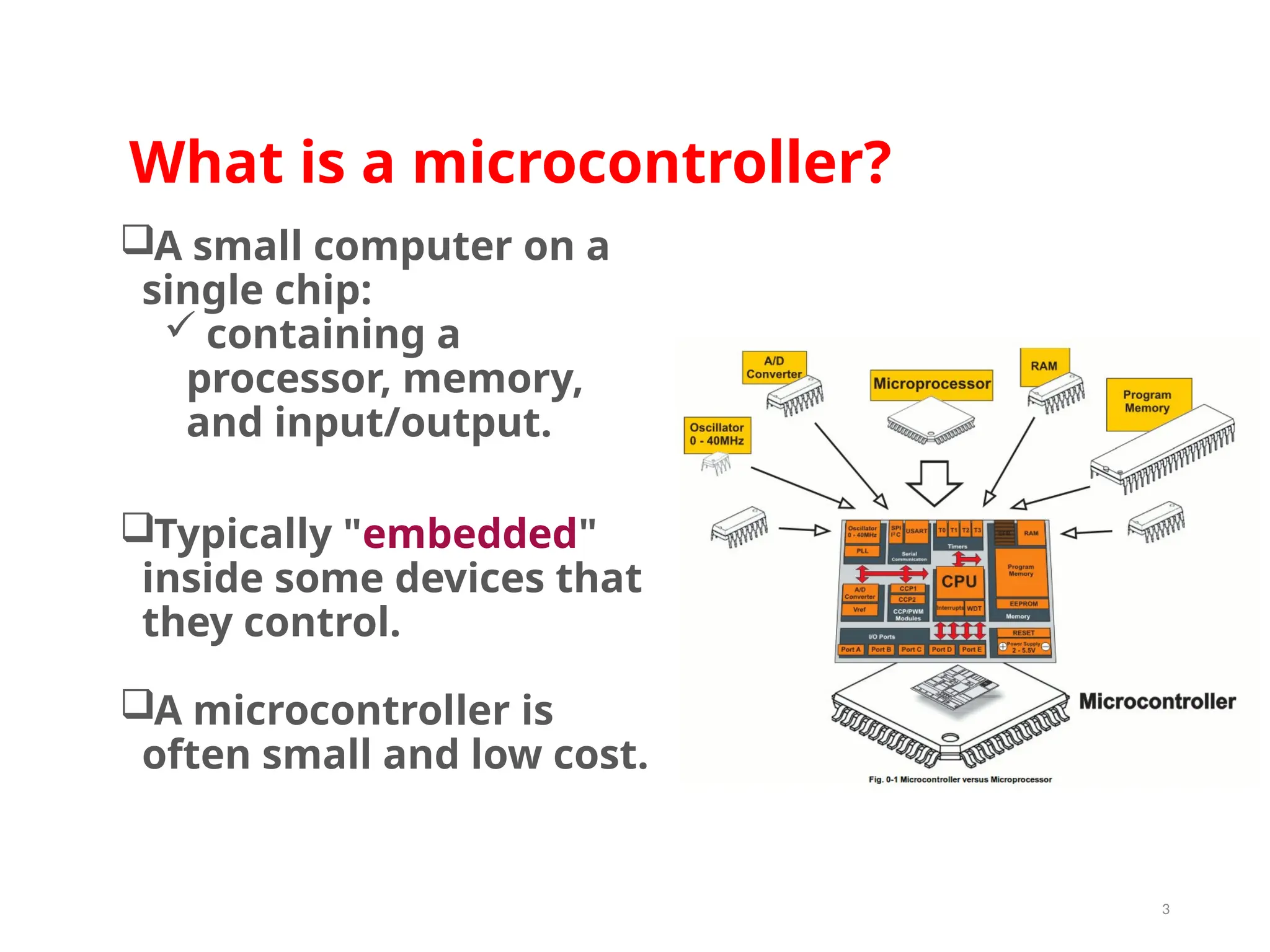
What is amicrocontroller? A small computer on a single chip: containing a processor, memory, and input/output. Typically "embedded" inside some devices that they control. A microcontroller is often small and low cost. 3
4.
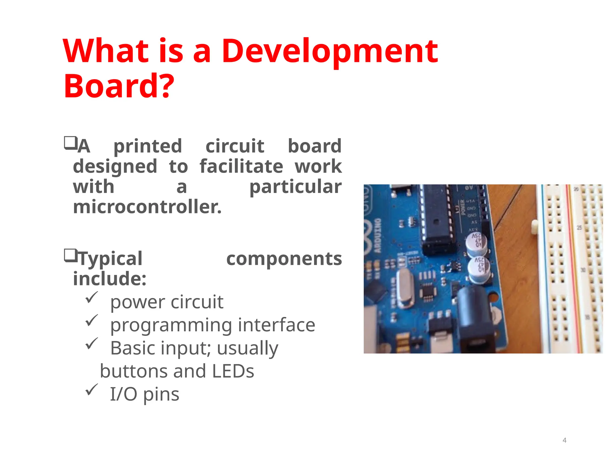
What is aDevelopment Board? A printed circuit board designed to facilitate work with a particular microcontroller. Typical components include: power circuit programming interface Basic input; usually buttons and LEDs I/O pins 4
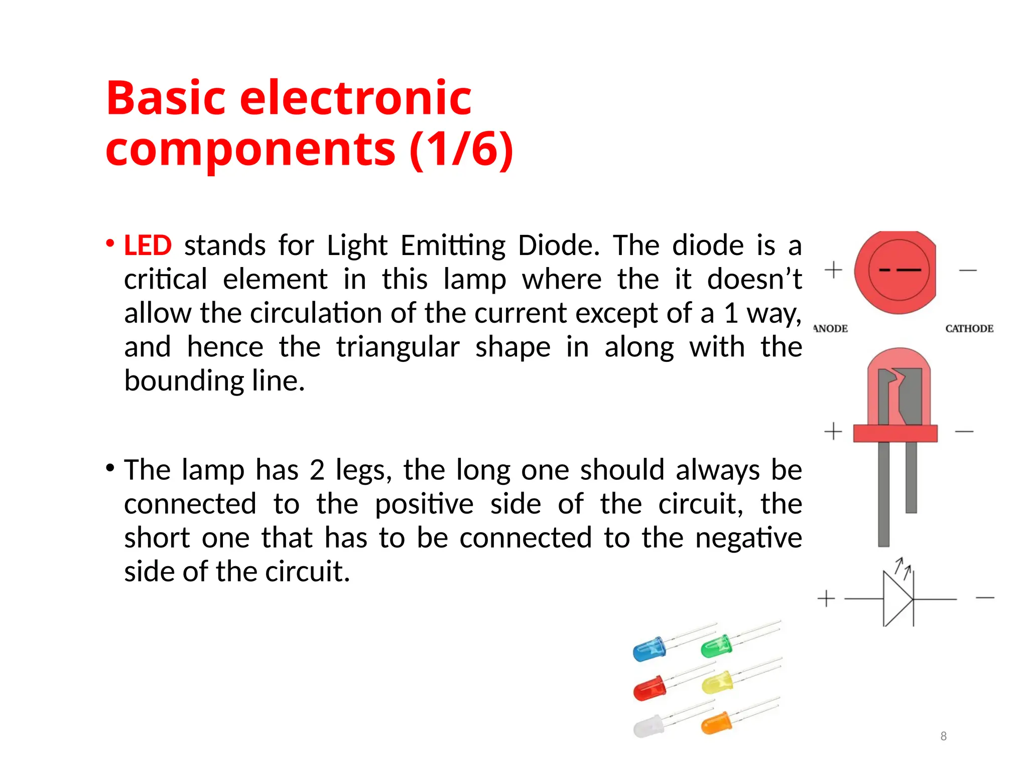
Basic electronic components (1/6) •LED stands for Light Emitting Diode. The diode is a critical element in this lamp where the it doesn’t allow the circulation of the current except of a 1 way, and hence the triangular shape in along with the bounding line. • The lamp has 2 legs, the long one should always be connected to the positive side of the circuit, the short one that has to be connected to the negative side of the circuit. 8
9.
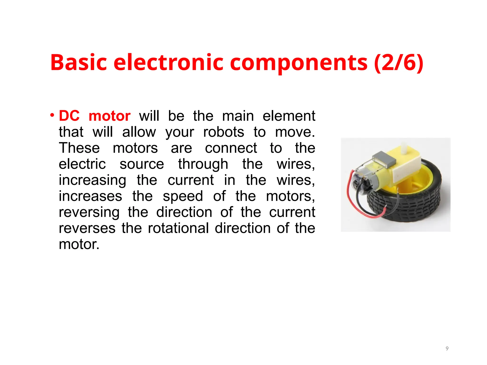
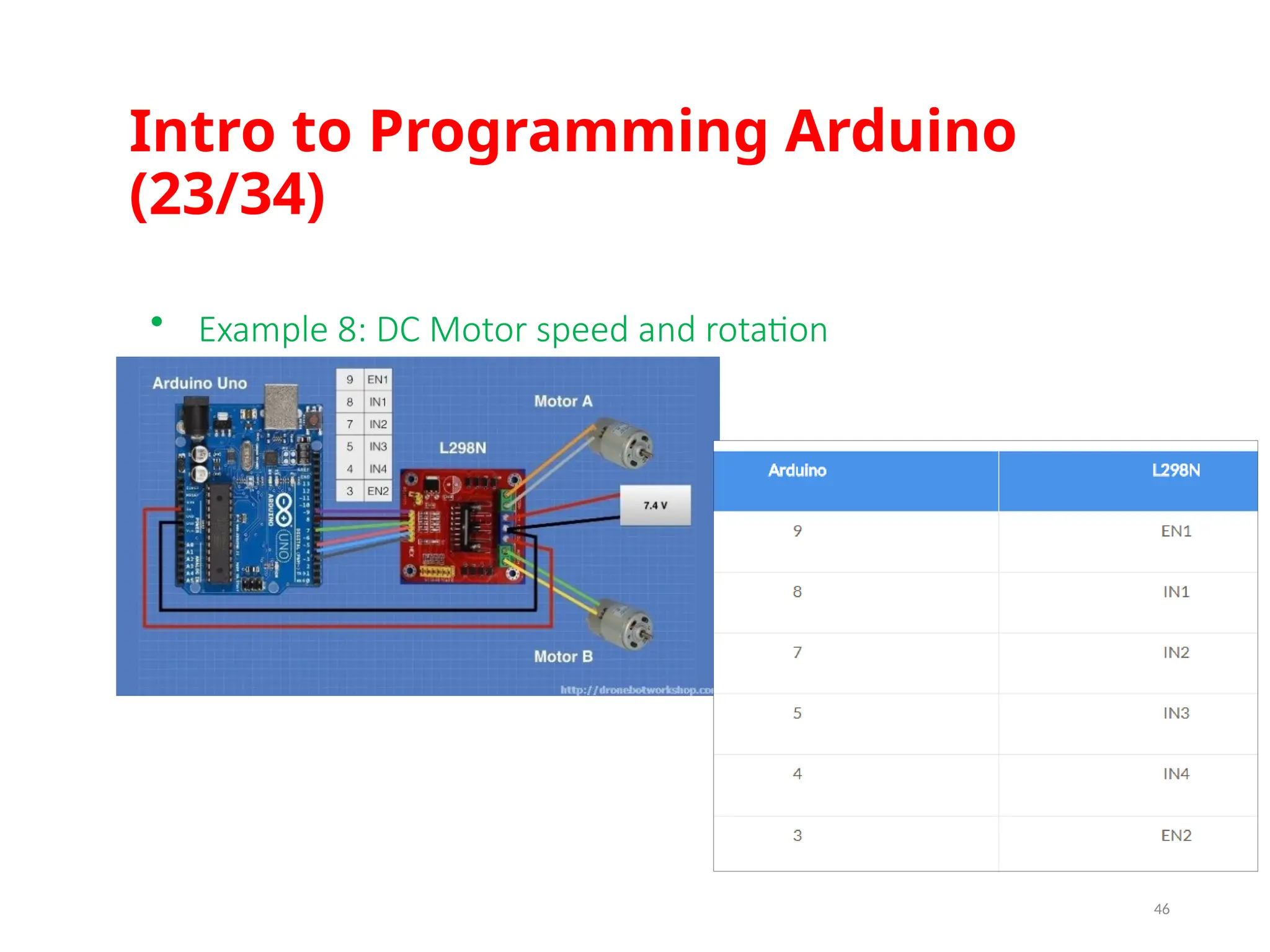
Basic electronic components(2/6) • DC motor will be the main element that will allow your robots to move. These motors are connect to the electric source through the wires, increasing the current in the wires, increases the speed of the motors, reversing the direction of the current reverses the rotational direction of the motor. 9
10.
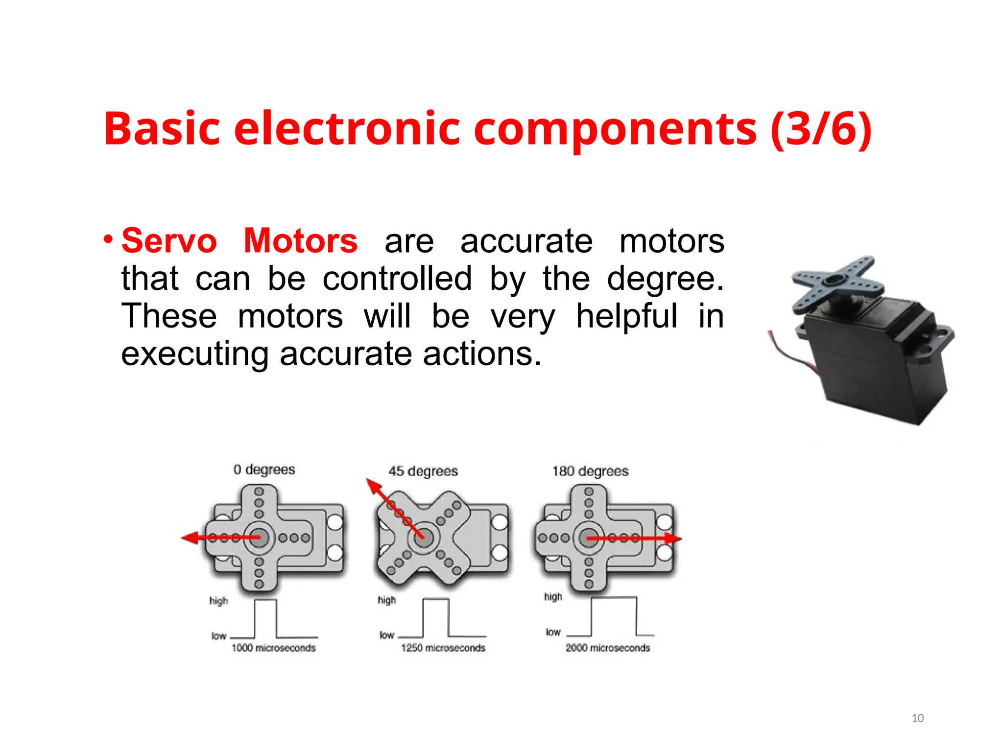
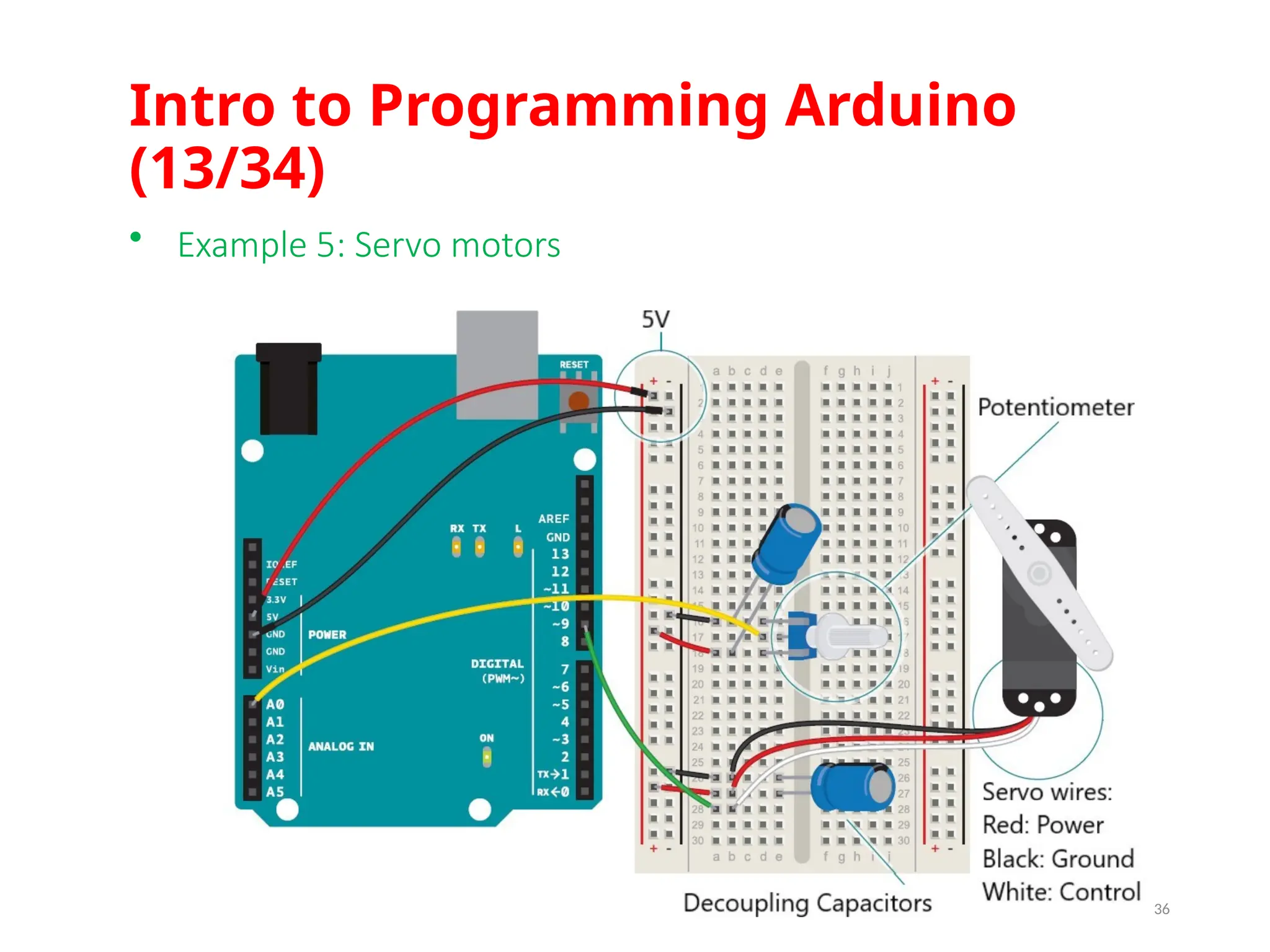
Basic electronic components(3/6) • Servo Motors are accurate motors that can be controlled by the degree. These motors will be very helpful in executing accurate actions. 10
11.
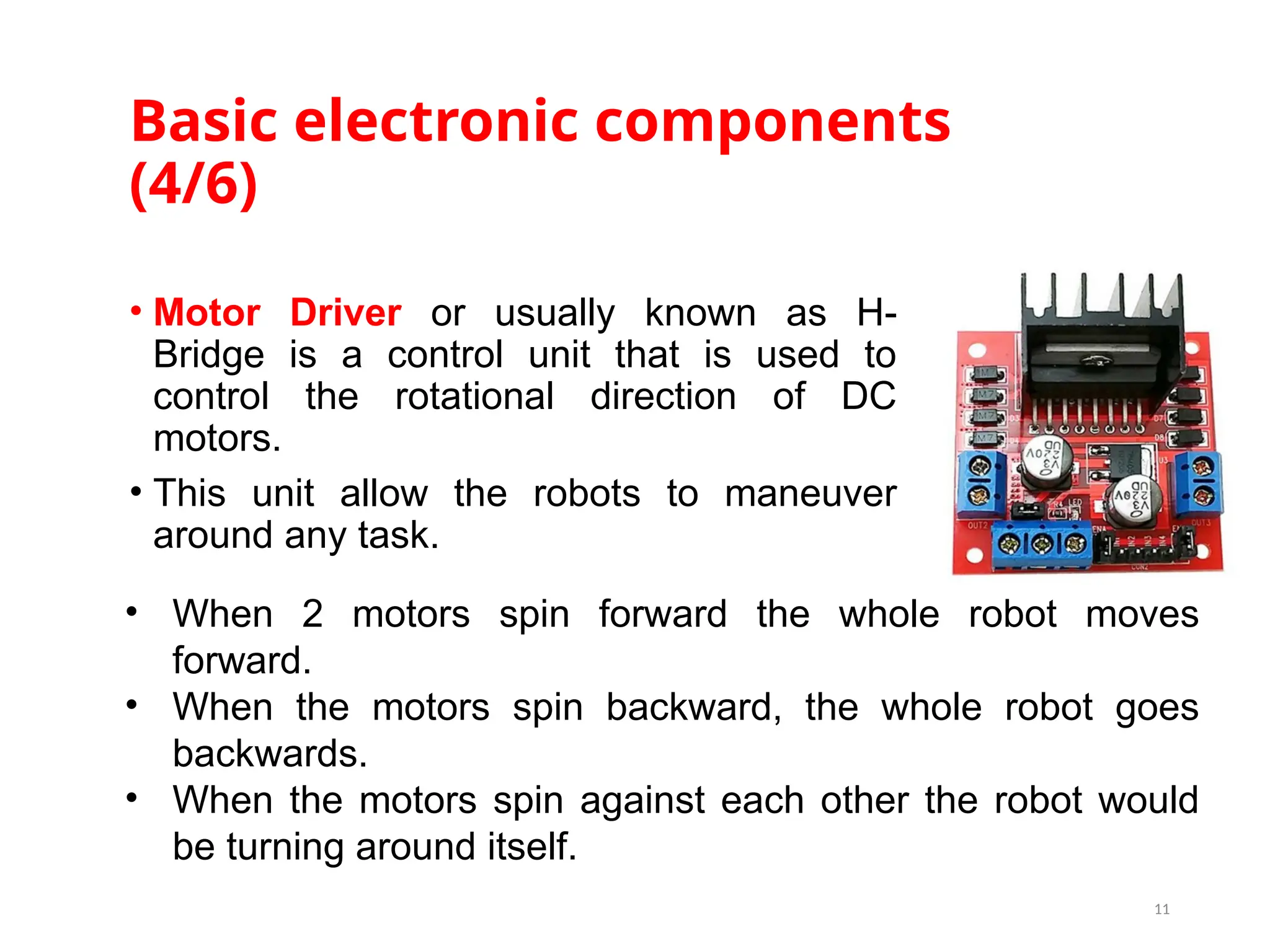
Basic electronic components (4/6) •Motor Driver or usually known as H- Bridge is a control unit that is used to control the rotational direction of DC motors. • This unit allow the robots to maneuver around any task. 11 • When 2 motors spin forward the whole robot moves forward. • When the motors spin backward, the whole robot goes backwards. • When the motors spin against each other the robot would be turning around itself.
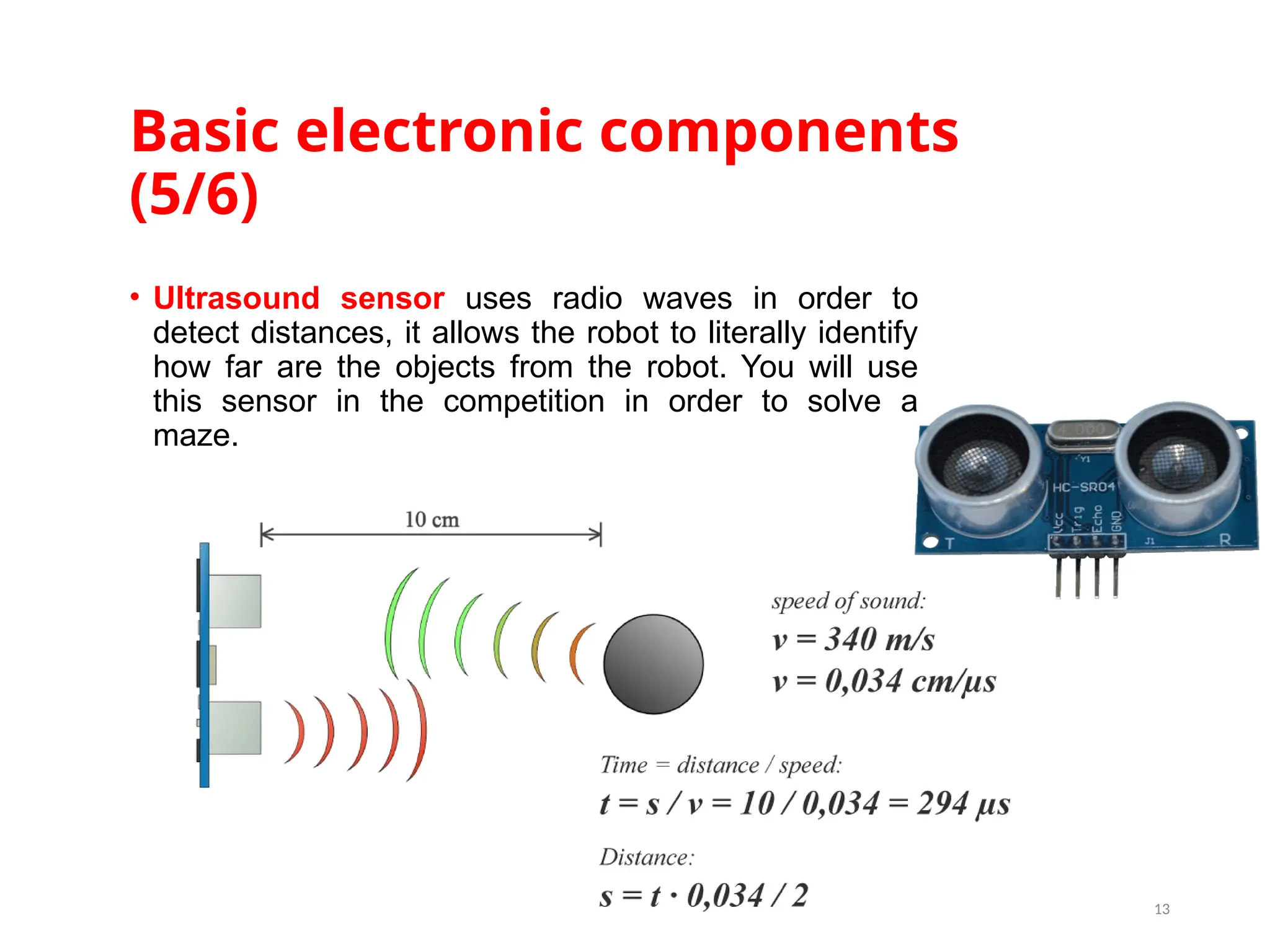
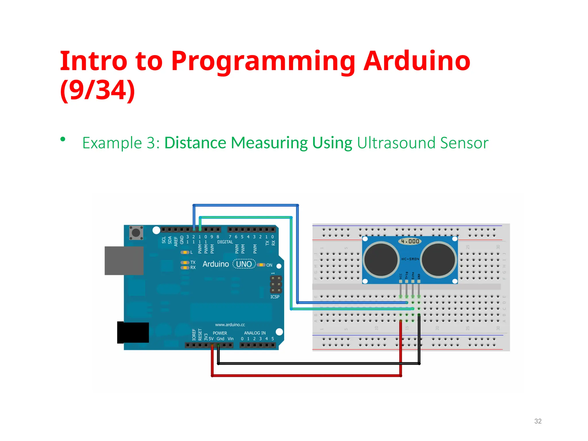
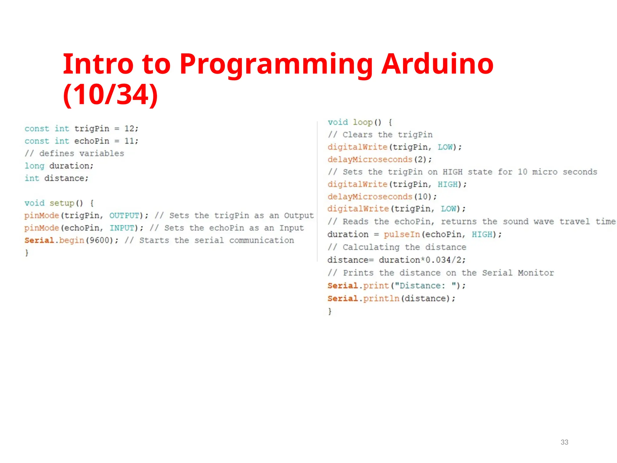
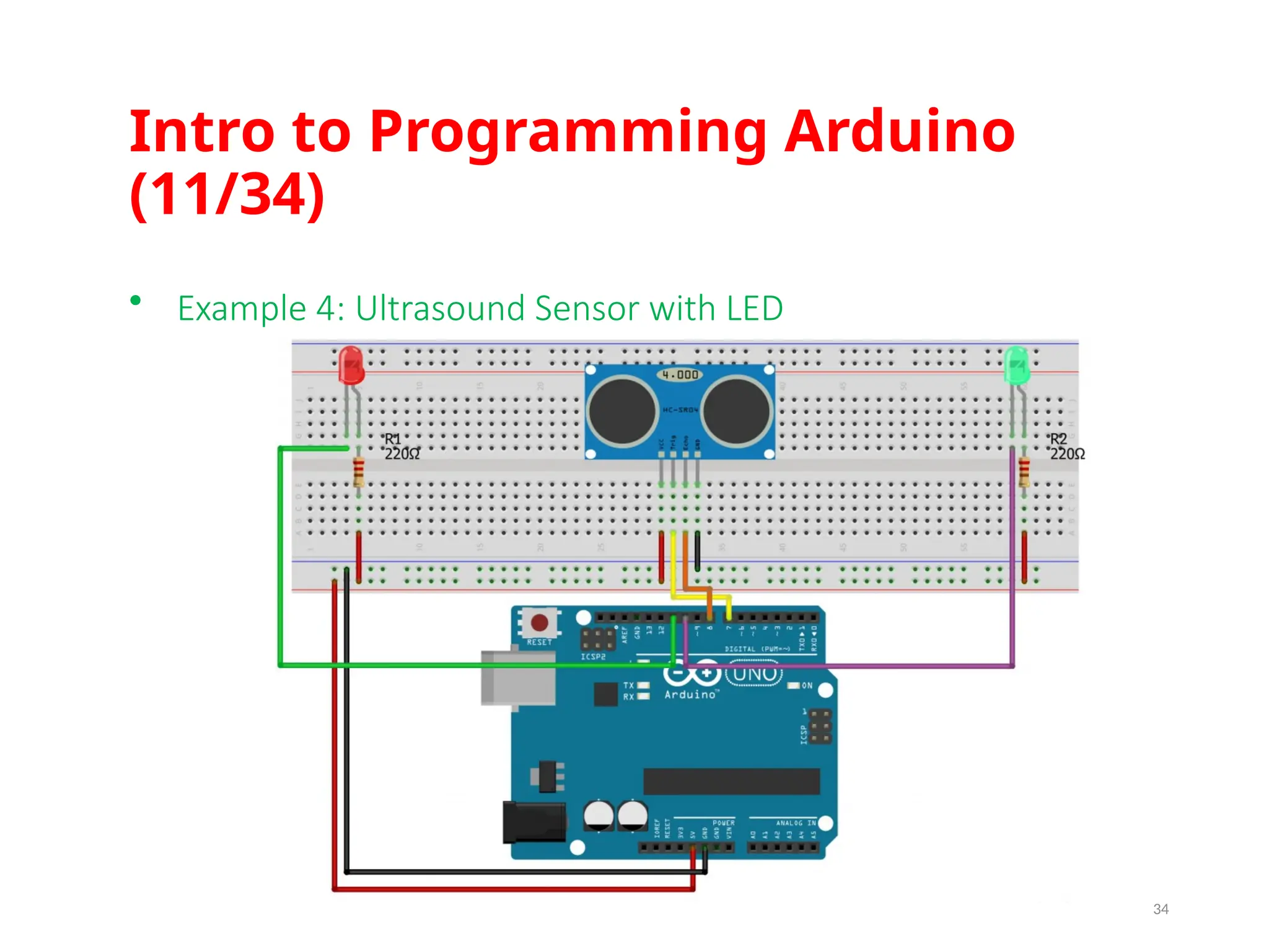
Basic electronic components (5/6) •Ultrasound sensor uses radio waves in order to detect distances, it allows the robot to literally identify how far are the objects from the robot. You will use this sensor in the competition in order to solve a maze. 13
14.
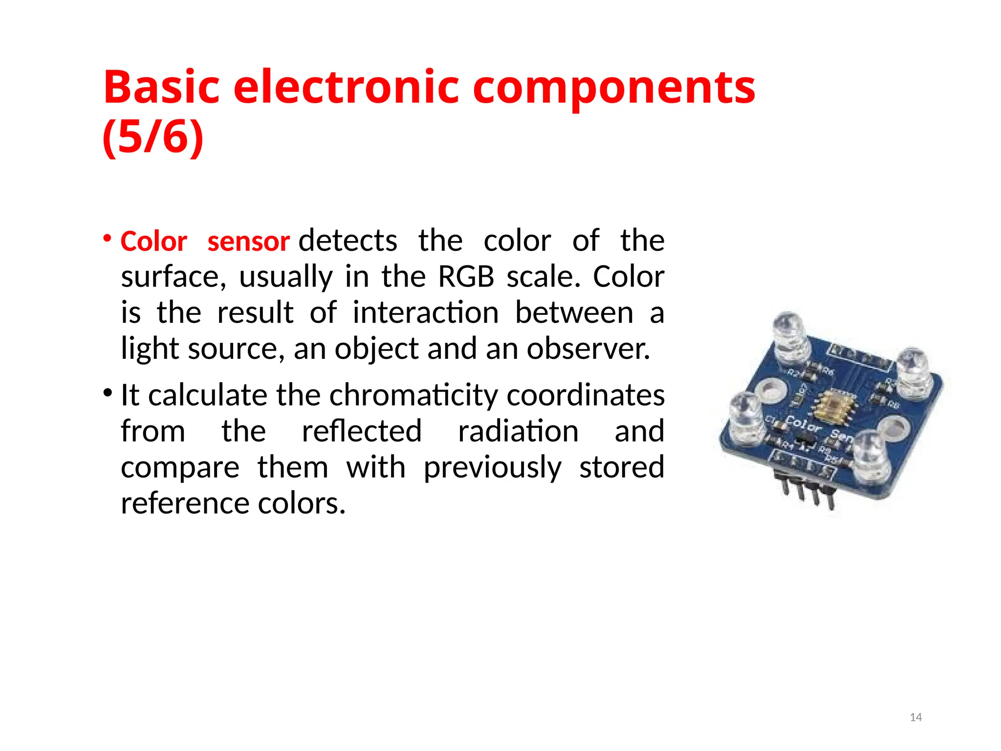
Basic electronic components (5/6) •Color sensor detects the color of the surface, usually in the RGB scale. Color is the result of interaction between a light source, an object and an observer. • It calculate the chromaticity coordinates from the reflected radiation and compare them with previously stored reference colors. 14
15.
Outline V. Getting Started VI.Intro to Programming Arduino VII. Sensors and motors with Arduino VIII.Motor control IX. Control servo motors I. Obstacle Avoider 15
16.
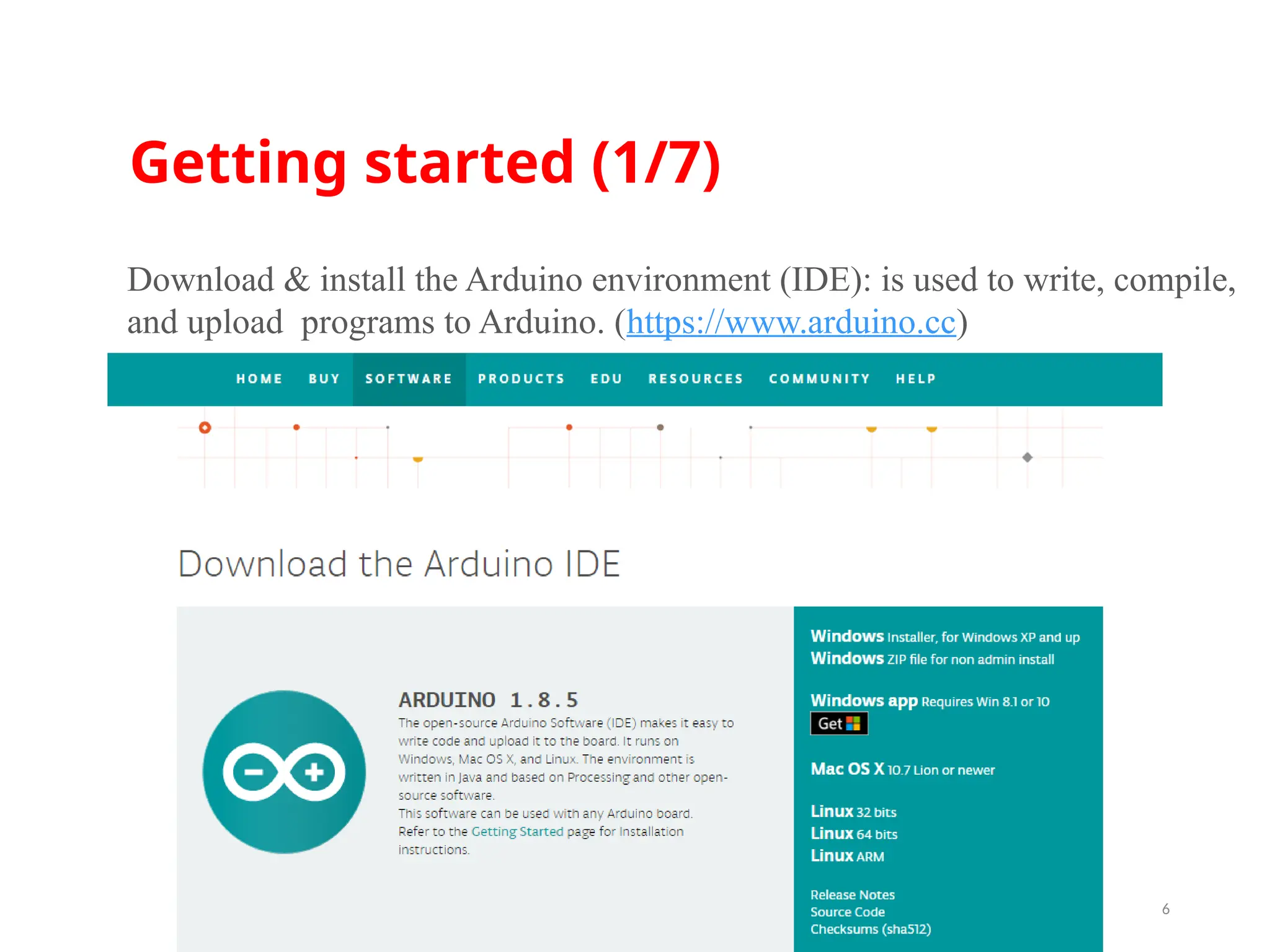
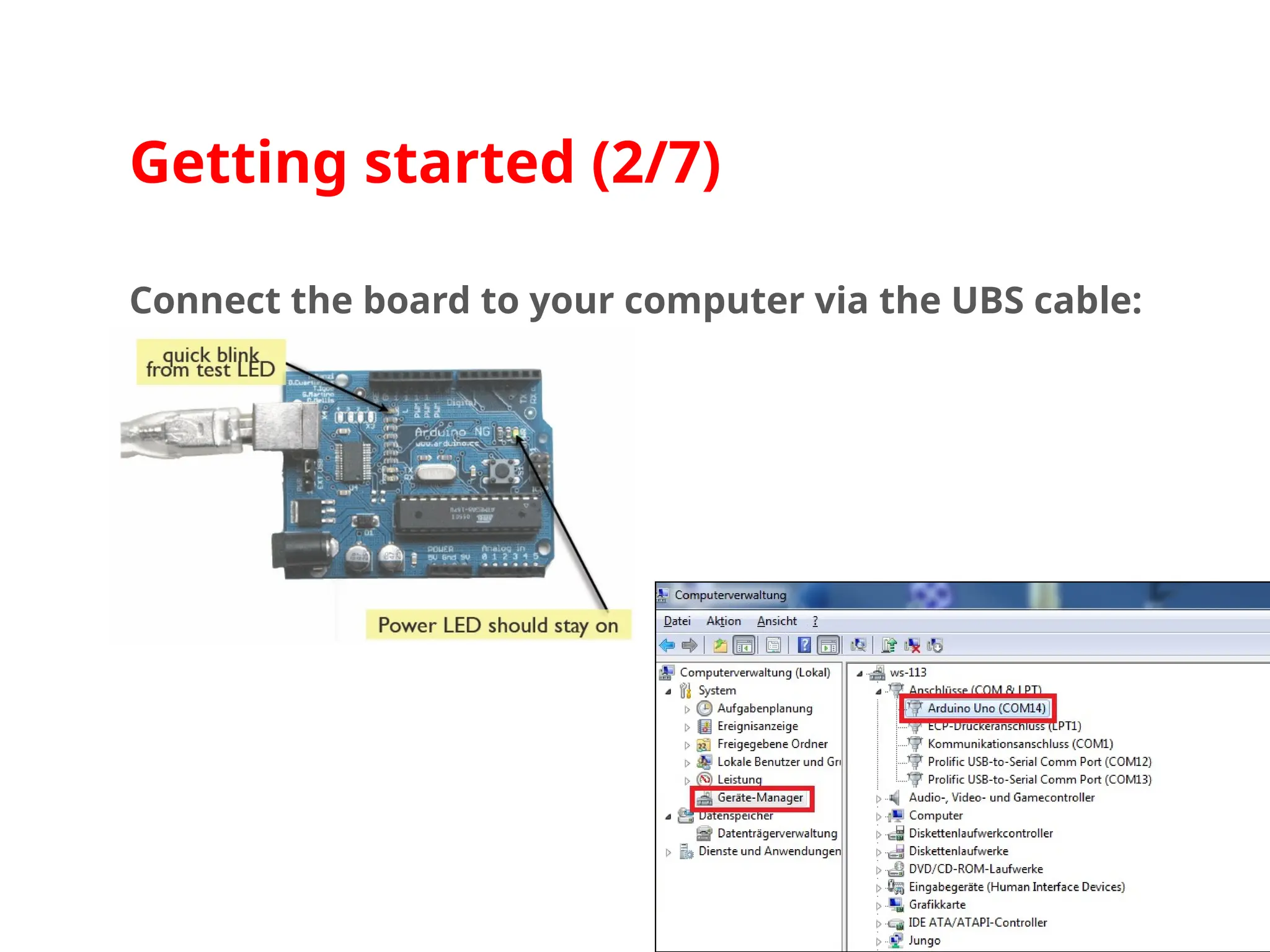
Getting started (1/7) 16 Download& install the Arduino environment (IDE): is used to write, compile, and upload programs to Arduino. (https://www.arduino.cc)
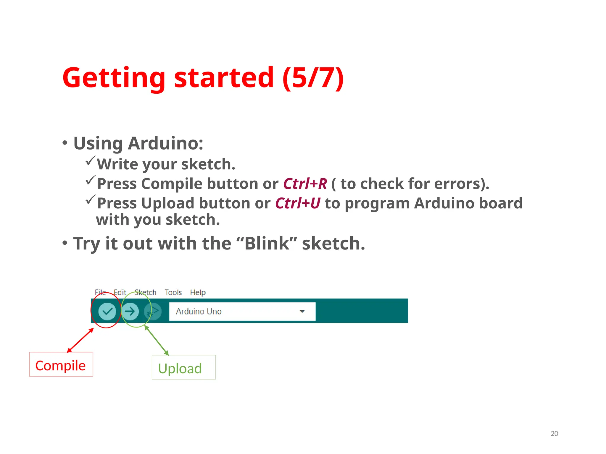
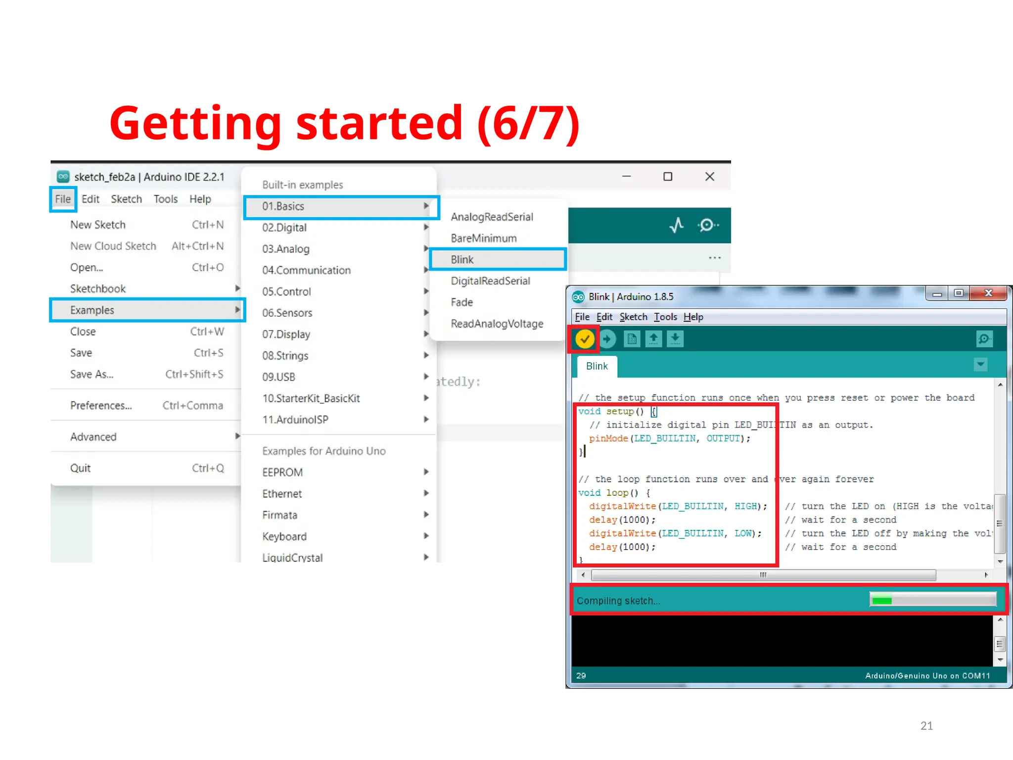
Getting started (5/7) •Using Arduino: Write your sketch. Press Compile button or Ctrl+R ( to check for errors). Press Upload button or Ctrl+U to program Arduino board with you sketch. • Try it out with the “Blink” sketch. 20 Compile Upload
Intro to ProgrammingArduino (1/34) • Basic Syntaxes 23 ; Semicolon Semicolons must always be used at end of each statement in your code. // Line Comments comments are used on order to clarify the written statements Variables Variables describe the type of the data you are using, which might be: Integer (Int) : any negative or Positive number excluding decimals Boolean (Bool) : only 0 or 1 Character : char used for characters such as letters
24.
Intro to ProgrammingArduino (2/34) 24 • Basic Syntaxes INPUT/OUTPUT These variables set pins for being inputs or outputs. HIGH/LOW These variables set the pins to high as ON or low as OFF. PINMODE pinMode is used in the setup part where you can use it to set up the Arduino Pins General statement : pinMode(pin#,OUTPUT or INPUT) Example : pinMode (13,INPUT) Here we have set Pint # 13 to act as an input
25.
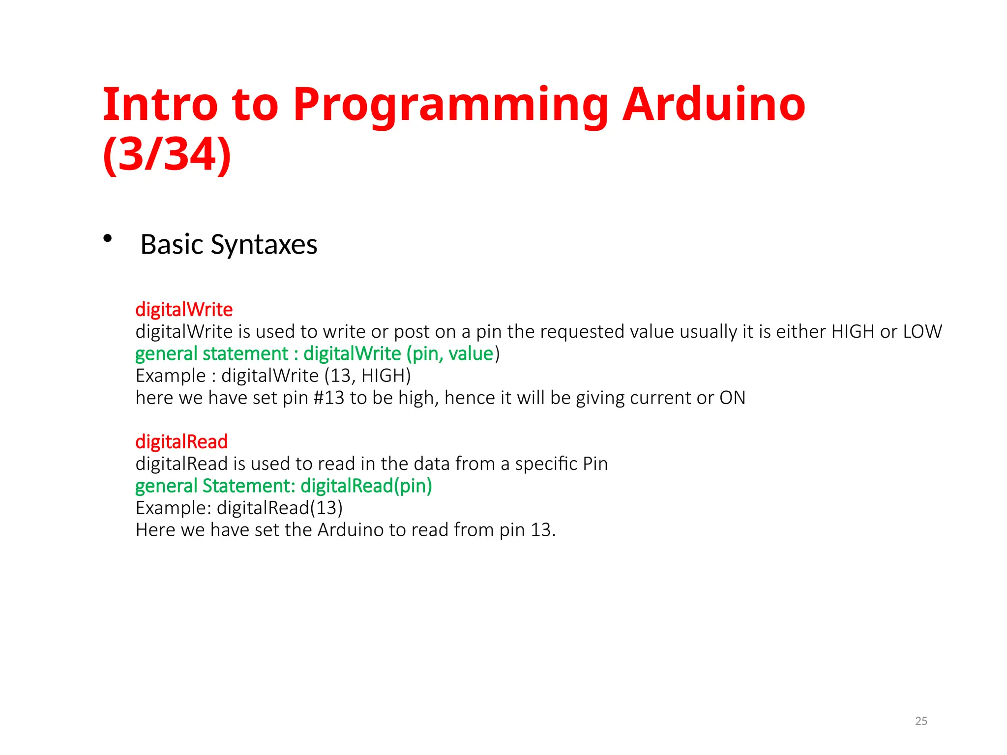
Intro to ProgrammingArduino (3/34) 25 • Basic Syntaxes digitalWrite digitalWrite is used to write or post on a pin the requested value usually it is either HIGH or LOW general statement : digitalWrite (pin, value) Example : digitalWrite (13, HIGH) here we have set pin #13 to be high, hence it will be giving current or ON digitalRead digitalRead is used to read in the data from a specific Pin general Statement: digitalRead(pin) Example: digitalRead(13) Here we have set the Arduino to read from pin 13.
26.
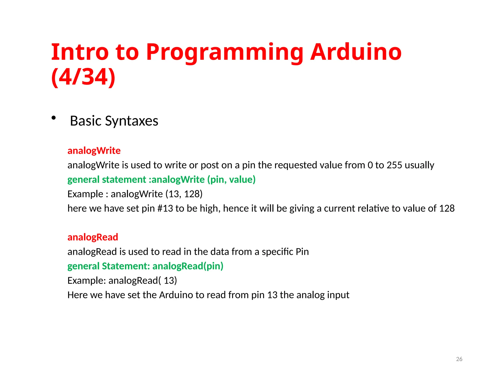
Intro to ProgrammingArduino (4/34) 26 analogWrite analogWrite is used to write or post on a pin the requested value from 0 to 255 usually general statement :analogWrite (pin, value) Example : analogWrite (13, 128) here we have set pin #13 to be high, hence it will be giving a current relative to value of 128 analogRead analogRead is used to read in the data from a specific Pin general Statement: analogRead(pin) Example: analogRead( 13) Here we have set the Arduino to read from pin 13 the analog input • Basic Syntaxes
27.
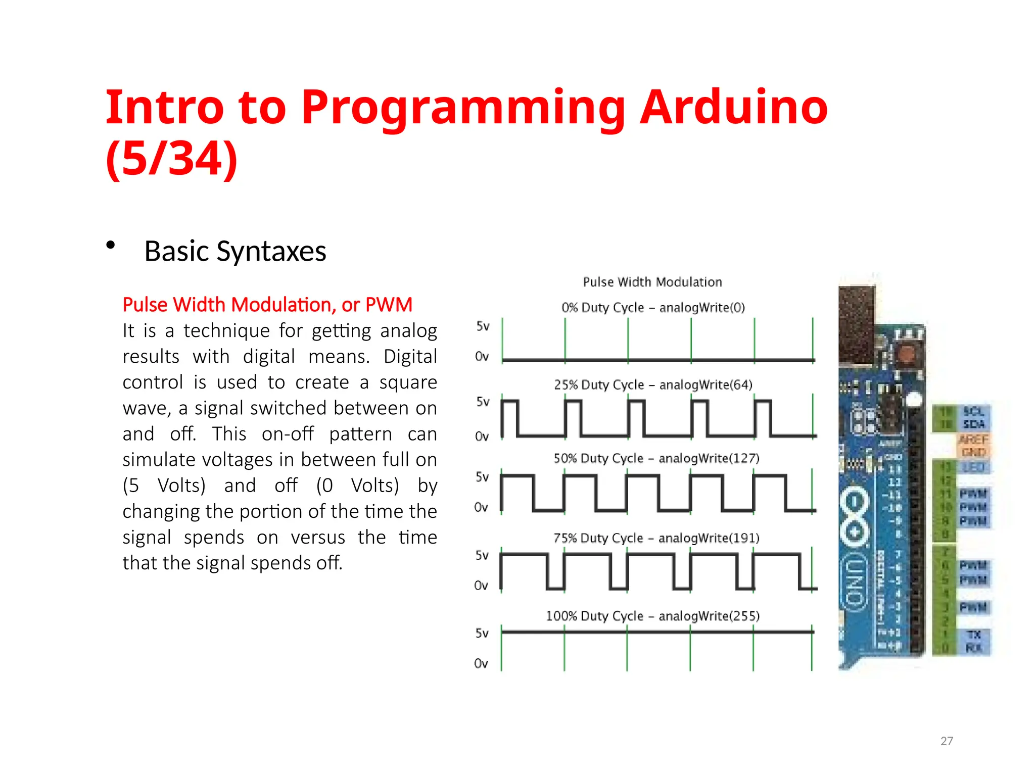
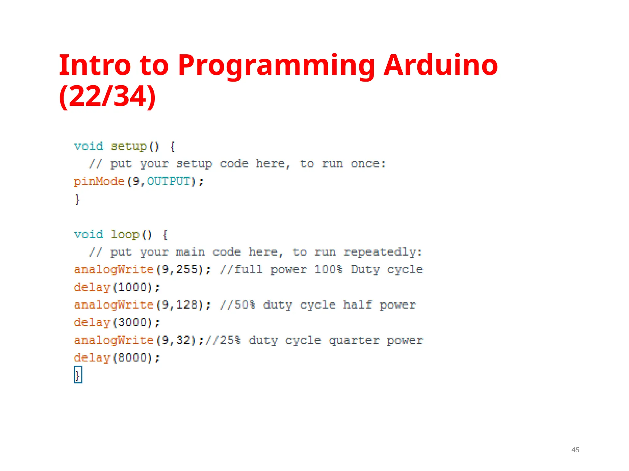
Intro to ProgrammingArduino (5/34) 27 • Basic Syntaxes Pulse Width Modulation, or PWM It is a technique for getting analog results with digital means. Digital control is used to create a square wave, a signal switched between on and off. This on-off pattern can simulate voltages in between full on (5 Volts) and off (0 Volts) by changing the portion of the time the signal spends on versus the time that the signal spends off.
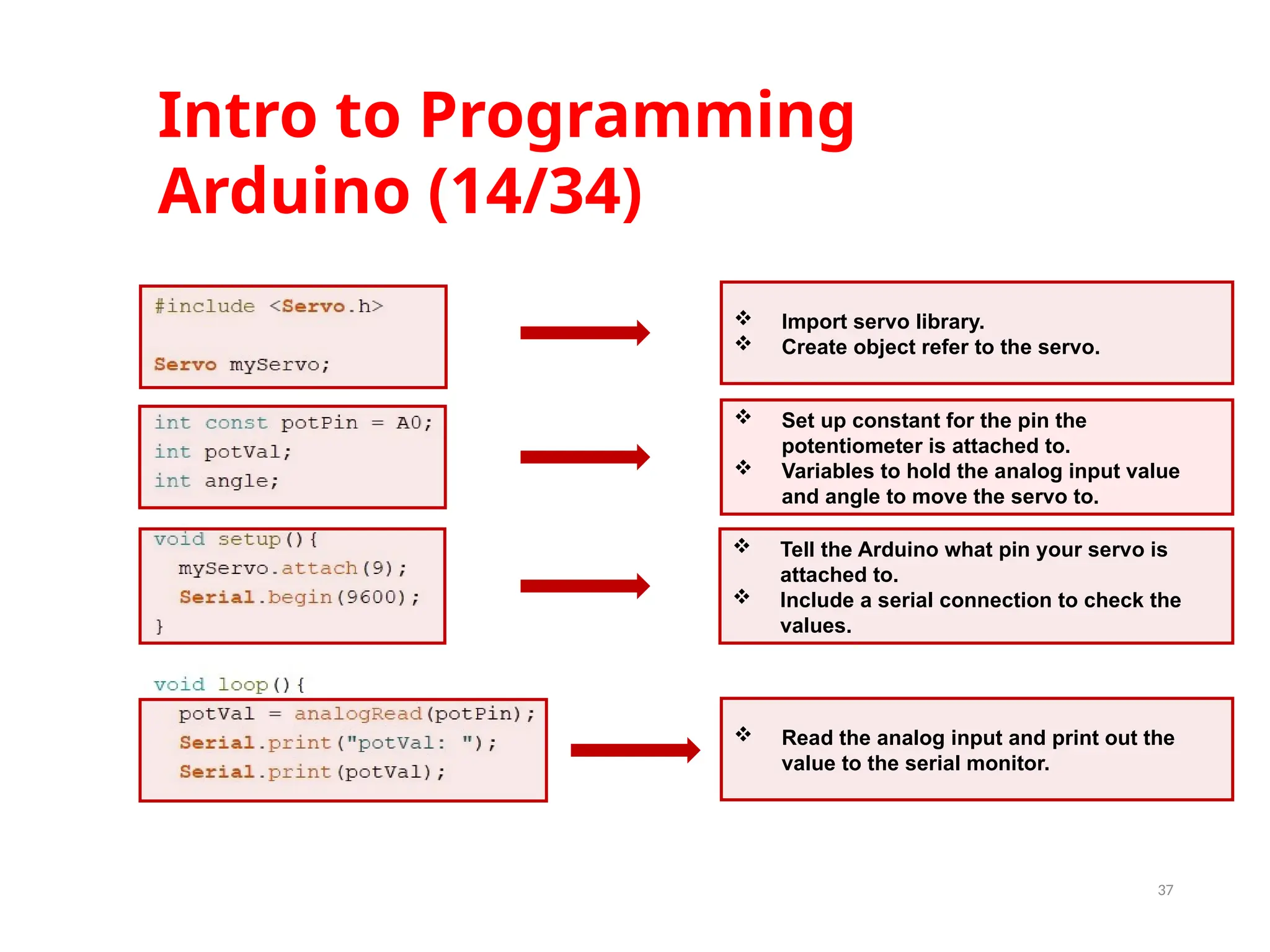
37 Tell theArduino what pin your servo is attached to. Include a serial connection to check the values. Set up constant for the pin the potentiometer is attached to. Variables to hold the analog input value and angle to move the servo to. Import servo library. Create object refer to the servo. Read the analog input and print out the value to the serial monitor. Intro to Programming Arduino (14/34)
38.
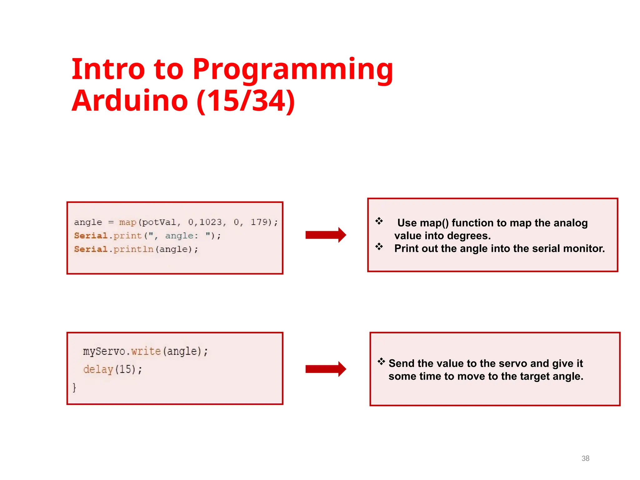
Intro to Programming Arduino(15/34) 38 Use map() function to map the analog value into degrees. Print out the angle into the serial monitor. Send the value to the servo and give it some time to move to the target angle.
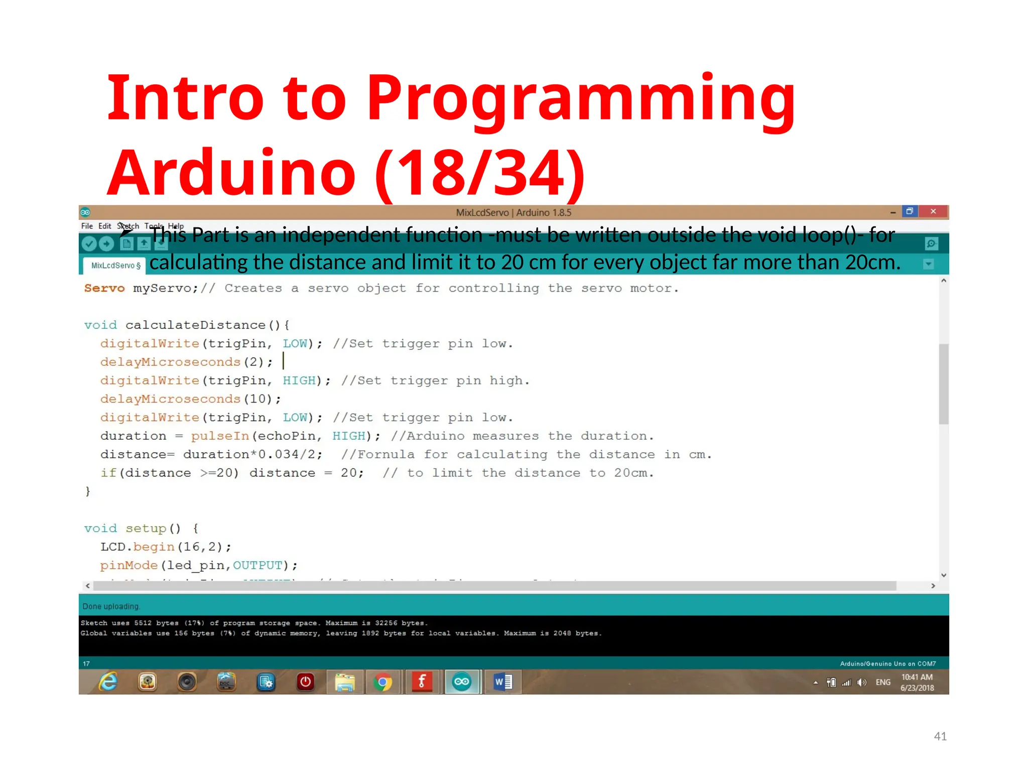
41 This Partis an independent function -must be written outside the void loop()- for calculating the distance and limit it to 20 cm for every object far more than 20cm. Intro to Programming Arduino (18/34)
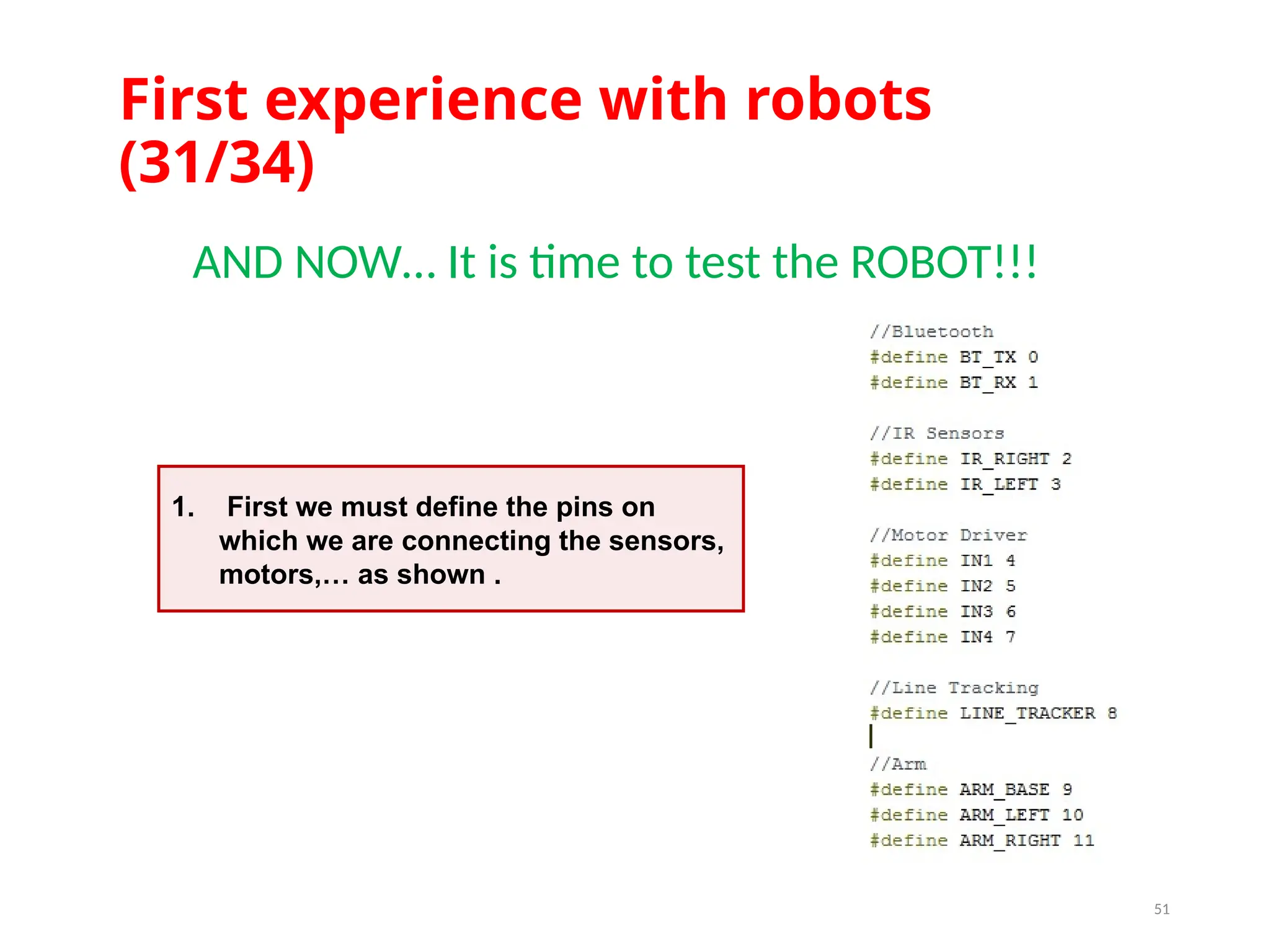
First experience withrobots (31/34) 51 AND NOW… It is time to test the ROBOT!!! 1. First we must define the pins on which we are connecting the sensors, motors,… as shown .
52.
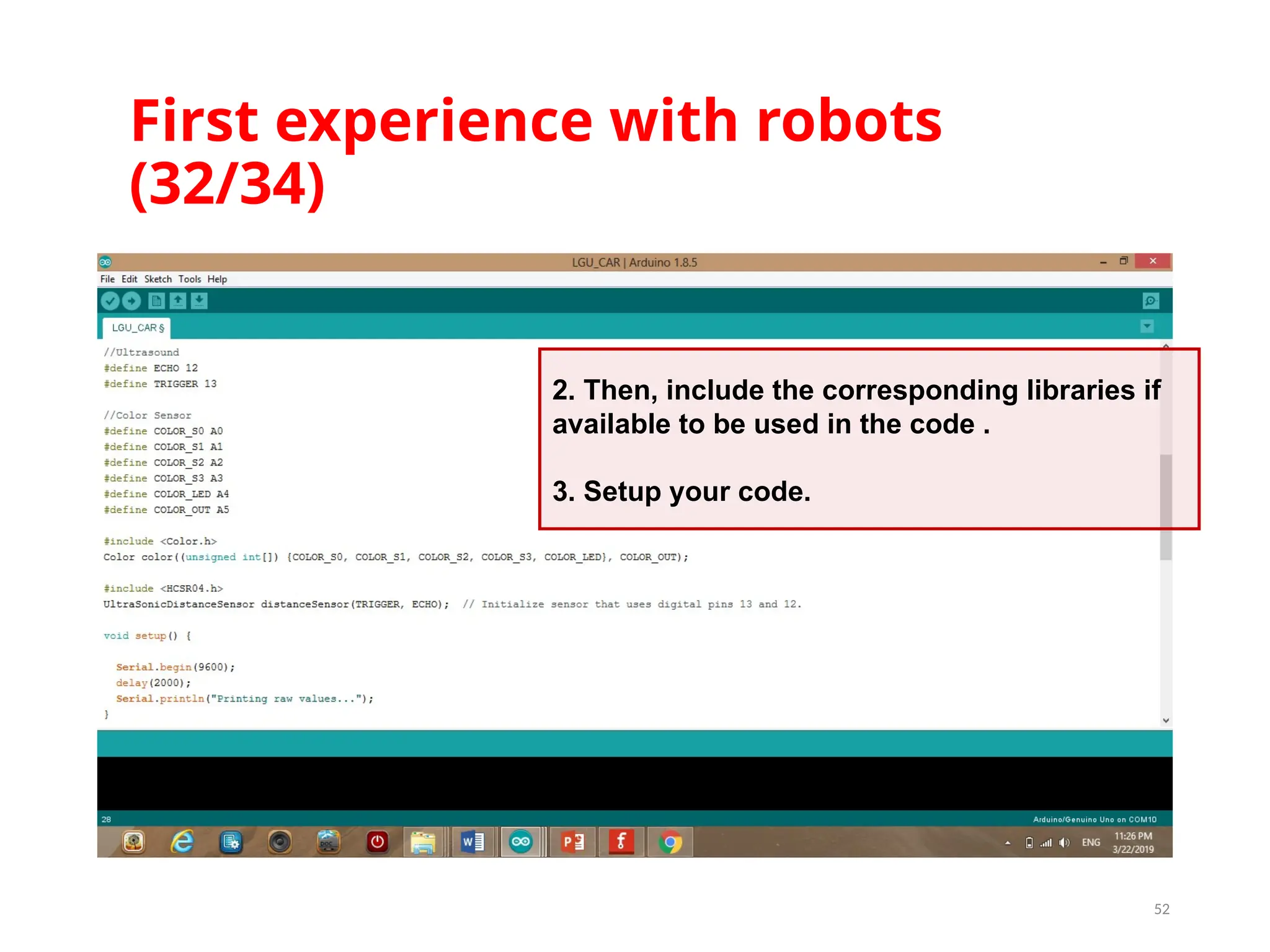
First experience withrobots (32/34) 52 2. Then, include the corresponding libraries if available to be used in the code . 3. Setup your code.
53.
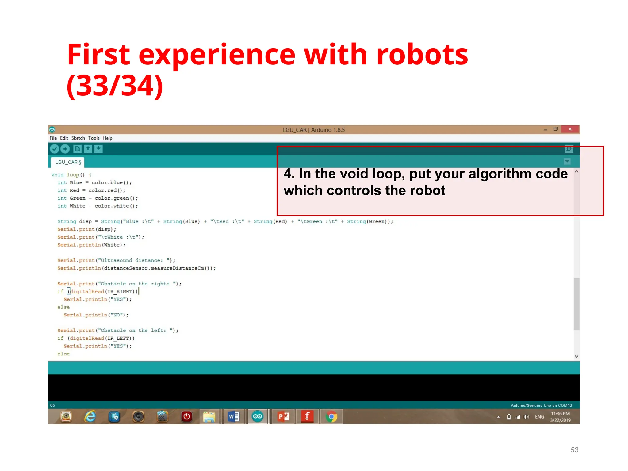
First experience withrobots (33/34) 53 4. In the void loop, put your algorithm code which controls the robot