Download to read offline
![IOSR Journal of Electrical and Electronics Engineering (IOSR-JEEE) e-ISSN: 2278-1676,p-ISSN: 2320-3331, Volume 10, Issue 1 Ver. III (Jan – Feb. 2015), PP 11-15 www.iosrjournals.org DOI: 10.9790/1676-10131115 www.iosrjournals.org 11 | Page Vision Based Object’s Dimension Identification To Sort Exact Material P. Prashanth.1 ,Mr.P. Saravanan.2 ,Dr.V.Nandagopal.3 1 M.E Student, Department of EEE, GanadipathyTulsi’s Jain Engineering College, Vellore-632102. 2 Assistant Professor, Department of EEE, GanadipathyTulsi’s Jain Engineering College, Vellore-632102. 3 Associate Professor, Department of EEE, GanadipathyTulsi’s Jain Engineering College, Vellore-632102. Abstract: Pick and place robotic Arms are used widely in Industrial application for over a decade. These robots are generally capable of sensing the appearance of object using proximity sensors and placing it in a commanded pallet. In this paper a same type of Robotic Arm is used, but as development in image processing technique, this Robot is capable of sensing the object’s Length, width and Radius using Vision system. The main objective here is to develop a special program to find the edges of an object in the image and to display its dimension. That can be used for sorting an exact object based on pattern matching technique using web camera. The application of this project also can be used in fields such as industry, military, medical and so on. Image processing are basically done in two techniques one is based on Hardware, such as ARM microcontrollers, another method is software based that is using softwares like MATLAB, LABVIEW. Here I have used second method to process the image.Objects dimension are found using LabVIEW’s special library tool. Simulation has been successfully taken to find the height and width of the object. Key words: Image Processing, Pattern Matching, Robotic Arm, Object Dimension, Labview IMAQ library. I. Introduction Robots used in industrial application is generally capable of handling heavy materials that are programmed to operate multifunctional mechanical parts that are designed to pick and place material, tools, parts and programmed to make varies movement and perform variety of tasks. Robots used in industrial application not only includes pick and place robotic arm but also requires sensors for the robot to do its tasks in sequence and also requires industrial vision camera or commercial camera with high resolutions to view the material and perform required tasks. Robots used in industrial application are reactive based, deliberative based, behavioral and hybrid based. Reactive based robots are sense and acttype robot. This means they sense the material through its sensors like ultrasonic, proximity to read the environment and react to it. In most case robots are used in hazardous places like high risk in Radiation for human and highly repetitive tasks that does not change from shift to shift. Rather than this condition robots are used to perform accurate material selection and handling. In this paper I had proposed a reactive based robot with vision guidance. These vision guided robot system are need to construct with three main core considerations, they are robotic system, visual system and bulk material handling system in hopper or conveyor system. This design is usually represented as vision guided robots (VGR). This design is fast growing in industrial material selection section to reduce manpower and reduce errors that are made by human carless. The main objective of this paper is to design a real time vision guided robotic arm. The vision system determines the exact shape and size of the objects that is randomly fed on a fixed place. The camera and the control software provides the robot system an accurate coordination between the objects, which are randomly spread under the camera field of vision, enabling the robotic arm to move and pick a selected object which is in the fixed pallet.This fixed pallet also contains a load cell to sense the weight of an object, to ensure that the objects weight is also correct. The pallet holding an object is fixed below the camera field, where the dimension and weight of the object is determined. A. Introduction to image processing The simple and very efficient method used to convert an image into digital form is called image processing. The image is to be converted into digital form in order to improve the quality of an image and also to extract the required useful information from it. Usually image processing system is based on treating images as two dimensional signals during conditioning of already set signal processing method to them [1] . In image processing thesemain steps are followed, 1. Image is acquired using optical scanner or by digital photography. 2. Image is analyzed and manipulated that includes data compressing and improving image quality. 3. In manipulation pixels are improved and any small gaps and holes are filled.](https://image.slidesharecdn.com/b010131115-151119094213-lva1-app6891/75/Vision-Based-Object-s-Dimension-Identification-To-Sort-Exact-Material-1-2048.jpg)
![Vision Based Object’s Dimension Identification To Sort Exact Material DOI: 10.9790/1676-10131115 www.iosrjournals.org 12 | Page 4. If the gap space is minimal it is filled, if it is large then it is considered as different object in the given image 5. Final step is the output in which the report is based on analysis done in that image. B. Purpose of Image processing There are five groups in stating the purpose of image processing, they are, 1. Image identification – Clearly observing the objects which are not visible. 2. Image restoration – This process sharpens the image to create a crisp image quality. 3. Image detection – This process helps to get the area of interest in the image. 4. Pattern Measurement – Measures the shape and size of the different objects in the image. 5. Recognizing the image – This process is used to distinguish varies object in the image. The above said processes are implemented in two methods based on the image material that is available[1] . They are, Analog image processing and digital image processing. Analog method is used when hard copies are used for image processing. Digital method is used in handling of digital image processing. II. Desing Methodology Of Robot 3 DOF (Degree Of Freedom) Pick and place robotic Arm is designed which will be controlled by the ARM microcontroller [4] . No change is done in design of this robotic arm. The same rules like trajectory control and kinematics are followed in designing this robotic arm[4] .ARM microcontroller is the heart of this robot. It asserts the motor drive to control the motors. Arm robots basically use servo motors for the movement of robot arm. In this paper I have used geared DC motor which will be convenient to control the speed of the robot arm. Grip design is very challenging in robot arm as it has to be designed to hold different type of objects in different types. In the gripper side a force sensor is attached which will sense the object presence and will be useful to hold the object without damaging it[7] . Fig.1 Image Acquisition and robot control unit The above fig 1 shows the ARM microcontroller controlling the motor drive that makes the geared dc motor to rotate forward and reverse. A digital output is programmed to control the motor drive. Only two analog input pins are used, that gets the analog signal from load cell and force sensor. As per the application of this industrial robotic arm an object that is to be sensed and image processed is arrived in a conveyor and held in a pallet which is under the camera. Under the pallet a load cell is kept to measure the weight of an object. An object’s weight and dimension are pre fed in the system software. First an arrived object’s weight is measured and compared with the pre fed weight in the program. If the measured object weight is same as the pre fed weight it is allowed to next process which is image processing. If the measured object weight is not same as the pre fed weight the ARM microcontroller asserts the motor drive to pick and place the object in rejected pallet. Here a commercial web camera with high resolution is used capture real time image of the object in the conveyer pallet. This process is done only when the object’s weight is as required. Web camera is interfaced with the personal computer or laptop to acquire and analyze the image. Here LabVIEW software is used for image processing. After the image is acquired, processed and analyzed the objects width and height are recognized and given in pixels. By keeping the output of the current object’s dimension in pixel it is compared with the pre fed dimension in the program.](https://image.slidesharecdn.com/b010131115-151119094213-lva1-app6891/75/Vision-Based-Object-s-Dimension-Identification-To-Sort-Exact-Material-2-2048.jpg)
![Vision Based Object’s Dimension Identification To Sort Exact Material DOI: 10.9790/1676-10131115 www.iosrjournals.org 13 | Page Now if the object’s dimension matches the dimension already fed into the program and the weight is already measured and compared, this object is selected and placed in the selected pallet.In case if the object’s dimension does not matches the pre fed dimension, that object is picked and placed in the rejected pallet. A. Image acquisition using LabVIEW To find the object’s width and height LabVIEW’s special library function is used which is IMAQ library. IMAQ (IMAgeAcQuisition) is a set of functions that controls the national instruments plug-in IMAQ devices for image acquisition and real time system integration bus multi board synchronization [2 .Steps involved in IMAQ image processing to find the dimension of object is, Step1- Imaq create [2] A temporary file space is created to store the acquired image. Step2- Imaq Cast IMage[2] The acquired image will be in the RGB form and this format will be very difficult to find the edges of the image. To overcome this difficulty the original image should be converted into gray scale. By using Imaq cast image RGB to Gray scale conversion is done. Step3 – Morphing Morphology is a technique used in image processing for dilation and erosion on gray scale and binary image processing [2] . Step4 – ImaqFillHole[2] ImaqFillhole is used to fill any holes at the center or anywhere in the image. This helps to avoid confusion in finding difference in gap between the objects and holes in the objects. Anyhow it can fill only small holes or gaps in the image. Step5:- Binary image The gray scale image is converted into binary image using imaq cast image to find the edges of the image. This helps in finding the width and height of the acquired image. III. Simulation Results The main function of this design is to find the dimension of an object through vision processing. For this purpose LabVIEW and its IMAQ library function is used. LabVIEW is virtual instrumentation software which is developed by National Instruments. Graphical type program is used in designing a required program. This type of language is also called as G language. Writing program in G language is simple and effective when compared with text based programming languages [9] . The fig.2 shows the front panel of the LabVIEW that is used to acquire the image from the saved file. It shows the selection for file path in which the image is stored and whose dimension is to be found. Fig.2 Front Panel for Image Acquisition The fig.3 shows the front panel of the LabVIEW with image acquired. When the image is selected and acquired from the selected file, it is temporarily stored in the program for further operations this condition is successfully done using Imaq Create [2] . After the image is selected it is processed to gray scale image and binary image in fraction of seconds and its edge is detected using area of interest and the objects height and width are recognized and its output is shown in pixels.The green LED indication indicates that the objects height and width matches the pre fed value and the green status LED indicates that the object is selected. The set value column provides the user to set the objects height and width that is to be selected. The actual value column shows the objects original size in pixels. Tolerance limit can also be set in order to match the practical errors during real time image acquisition that does](https://image.slidesharecdn.com/b010131115-151119094213-lva1-app6891/75/Vision-Based-Object-s-Dimension-Identification-To-Sort-Exact-Material-3-2048.jpg)
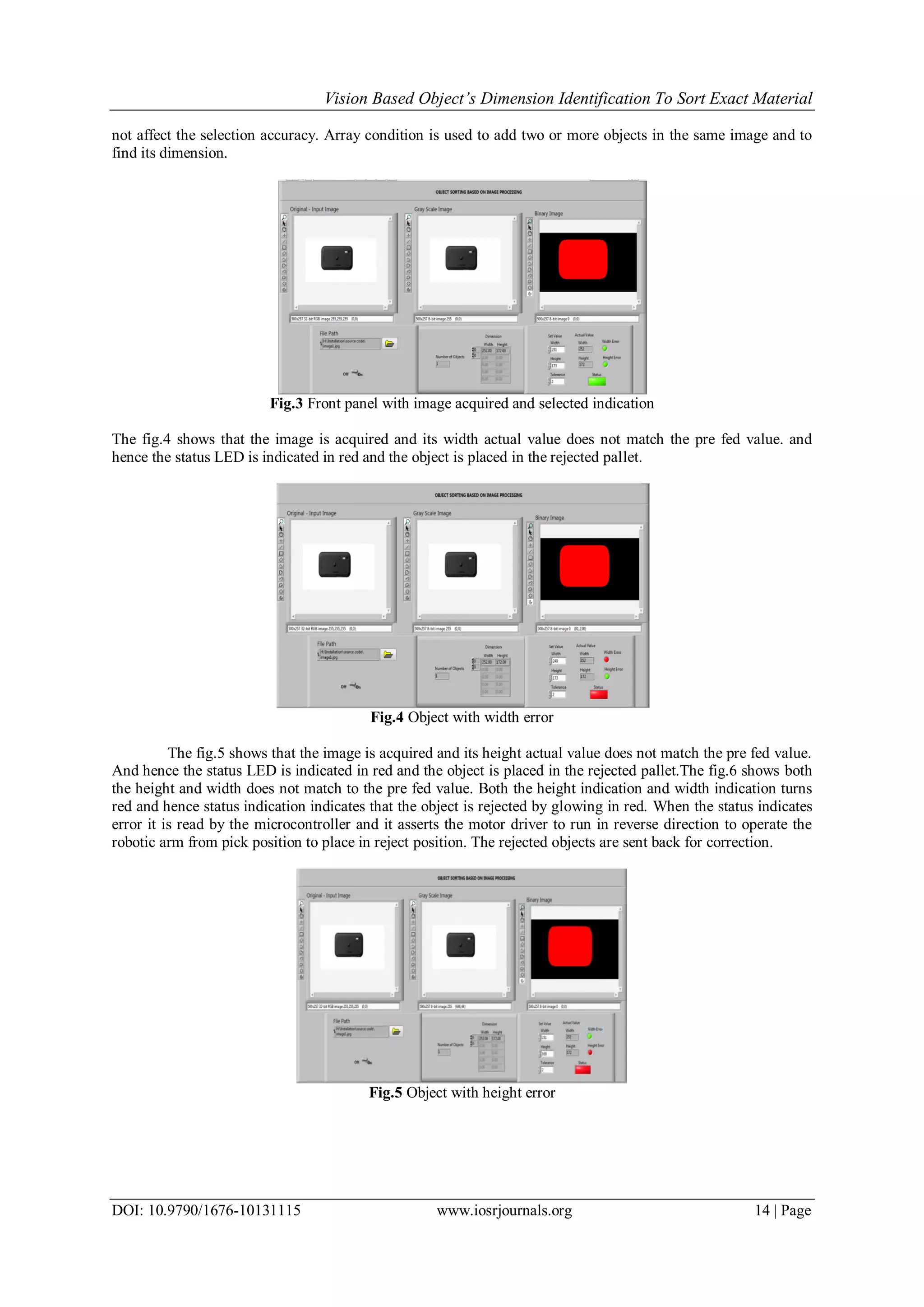
![Vision Based Object’s Dimension Identification To Sort Exact Material DOI: 10.9790/1676-10131115 www.iosrjournals.org 15 | Page Fig.6 object with height and width error IV. Conclusion This paper discusses the steps and methods involved in finding the objects dimension using LabVIEW Imaq library function. By this proposed model an accurate object is selected that is with required height and width in common, with required dimension. The simulation result shows successfully measured height and width of the object and it is displayed in the front panel of LabVIEW software. V. Future Scope In this proposed system the camera is to be in the fixed position. If the camera position varies the objects dimension also varies as the image zooms in and out it affects the pixel rate. This disadvantage is to be overcome in the future execution of this system. References [1]. http://www.engineersgarage.com/articles/image-processing-tutorial-applications [2]. IMAQ Vision for LabVIEWUser Manual August 2004 edition. [3]. Roland Szabo, Ioan Lie “Automated Colored Object Sorting Application for Robotic Arms” 2012 IEEE. [4]. Wong Guan Hao, Yap Yee Leck and Lim Chot Hun “6-DOF PC-BASED ROBOTIC ARM (PC-ROBOARM) WITH EFFICIENT TRAJECTORY PLANNING AND SPEED CONTROL” 2011 4th International Conference on Mechatronics (ICOM), 17-19 May 2011, Kuala Lumpur, Malaysia. [5]. Yong Zhang, Brandon K. Chen, Xinyu Liu, Yu Sun “Autonomous Robotic Pick-and-Place of Microobjects” IEEE TRANSACTIONS ON ROBOTICS, VOL. 26, NO. 1, FEBRUARY 2010. [6]. Haoxiang Lang, Ying Wang, Clarence W. de Silva, “Vision Based Object Identification and Tracking for Mobile Robot Visual Servo Control” 2010 8th IEEE International Conference on Control and Automation Xiamen, China, June 9-11, 2010. [7]. Gourab Sen Gupta, Subhas Chandra Mukhopadhyay, Christopher H. Messom, Serge N. Demidenko “Master–Slave Control of a Teleoperated Anthropomorphic Robotic Arm With Gripping Force Sensing” IEEE TRANSACTIONS ON INSTRUMENTATION AND MEASUREMENT, VOL. 55, NO. 6, DECEMBER 2006. [8]. Richard A. McCourt and Clarence W. de Silva “Autonomous Robotic Capture of a Satellite Using Constrained Predictive Control” IEEE/ASME TRANSACTIONS ON MECHATRONICS, VOL. 11, NO. 6, DECEMBER 2006. [9]. UmeshRajashekar, George C. Panayi, Frank P. Baumgartner, and Alan C. Bovik “The SIVA Demonstration Gallery for Signal, Image, and Video Processing Education” IEEE TRANSACTIONS ON EDUCATION, VOL. 45, NO. 4, NOVEMBER 2002. [10]. Rahul Singh Richard M. Voyles David Littau Nikolaos P. Papanikolopoulos “Grasping Real Objects Using Virtual Images” Proceedings of the 37th IEEE Conference on Decision &ControlTampa, Florida USA December 1998.](https://image.slidesharecdn.com/b010131115-151119094213-lva1-app6891/75/Vision-Based-Object-s-Dimension-Identification-To-Sort-Exact-Material-5-2048.jpg)

This document describes a vision-based system using a robotic arm and image processing to identify the dimensions of objects and sort them. A 3 DOF robotic arm picks objects from a conveyor belt. A load cell first measures the weight and compares it to a preset value. If it matches, a camera captures an image that is processed using LabVIEW to determine the object's width and height in pixels. These are compared to preset dimension values. If dimensions match the weight, the object is sorted into an "accepted" pallet. Otherwise, it is placed in a "rejected" pallet. The system aims to accurately sort objects by both weight and size using integrated sensing, vision processing, and robotic manipulation.