This document provides an overview of sensor networks and wireless sensor network architectures. It begins with an introduction to wireless sensor networks and their components. It then discusses the topics, challenges, and enabling technologies for WSNs. The document outlines the architecture of a sensor node and its goals. It provides examples of WSN applications and discusses sensor network deployment considerations. Finally, it addresses the design challenges, operational challenges, and required mechanisms for WSNs to meet their requirements.
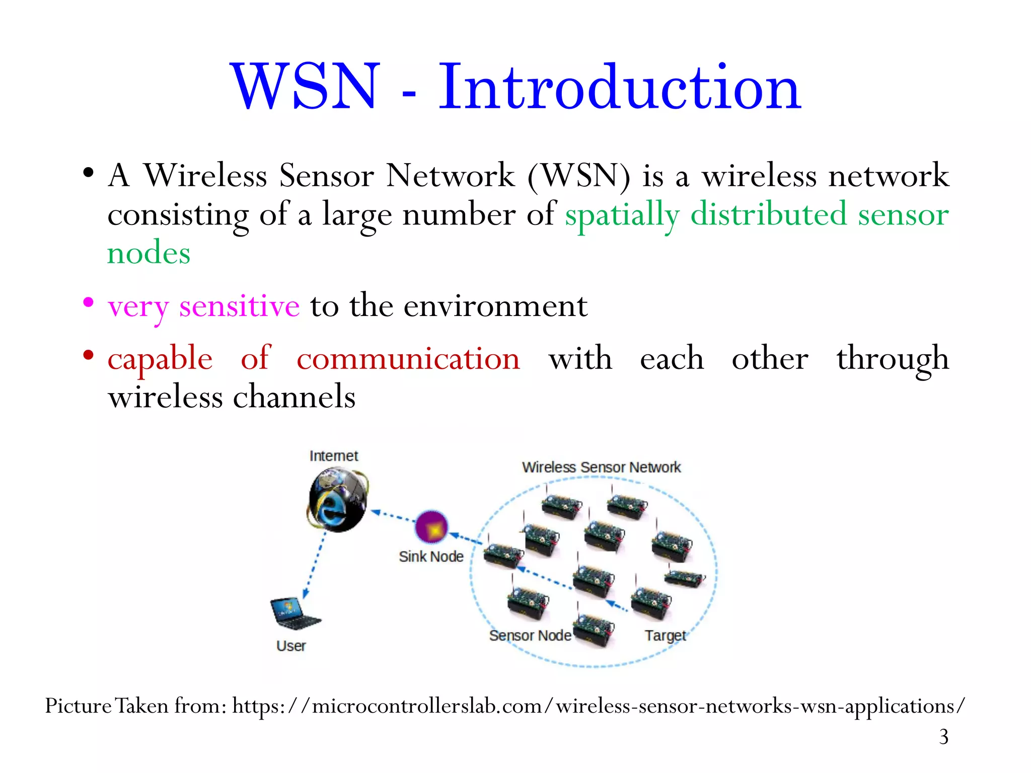
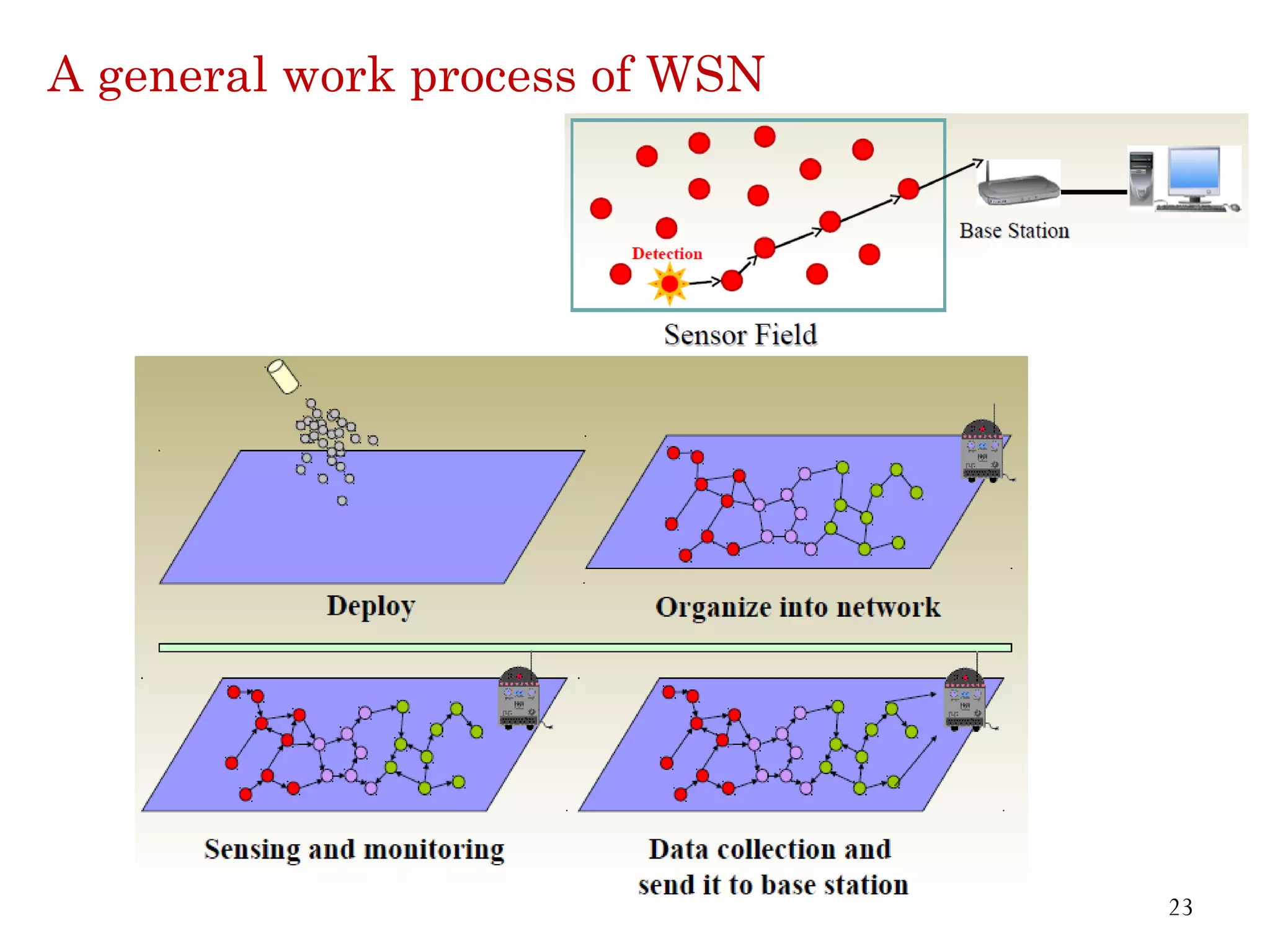
WSN - Introduction •A Wireless Sensor Network (WSN) is a wireless network consisting of a large number of spatially distributed sensor nodes • very sensitive to the environment • capable of communication with each other through wireless channels PictureTaken from: https://microcontrollerslab.com/wireless-sensor-networks-wsn-applications/ 3
4.
Sensor & SensorNodes • Sensor Network is an infrastructure comprised of sensing, computing and communication elements that give the ability of observing and reacting to events in a specified environment to an administrator. • The Administrator typically is a civil, governmental, commercial or industrial entity. • The environment can be a physical world, a biological system, or an information technology framework. 4
5.
Contd… • Sensing isa Technique used to gather information about physical object or Process, Including occurrence of the event. • An Object performing such a sensing task is called a sensor. • For eg: Remote Sensors • The human body is equipped with sensors that are able to capture optical information from the environment • Acoustic information such as sounds (ears) and smell (Nose) • A sensor is a device that translates parameters or events in the physical world into signals that can be measured and analyzed. 5
6.
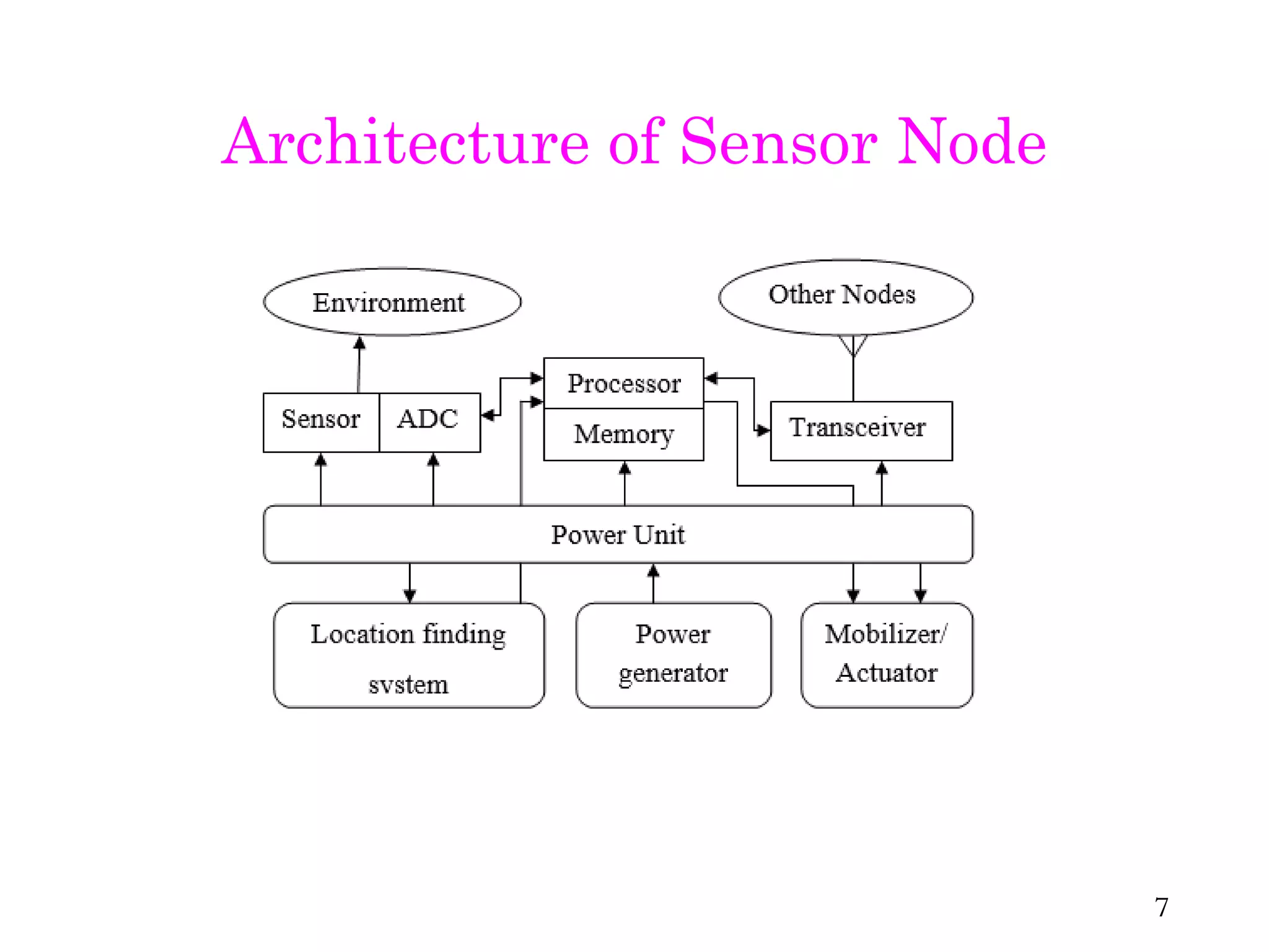
• A sensoris a electronic device that measures a physical quantity and converts it into a signal which can be read by an observer or by an instrument. • Sensor Node : Basic unit in Sensor Network Picture taken from : https://www.researchgate.net/publication/312332362_Application aware _ Energy _ Efficient_Centralized_Clustering_Routing_Protocol_for_Wireless_Sensor_Networks/figures?lo=1 6
Goal of aSensor Node • The goal from the sensor node is • to collect the data at regular intervals • then transform the data into an electrical signal • finally send the signal to the sink or the base node 8
9.
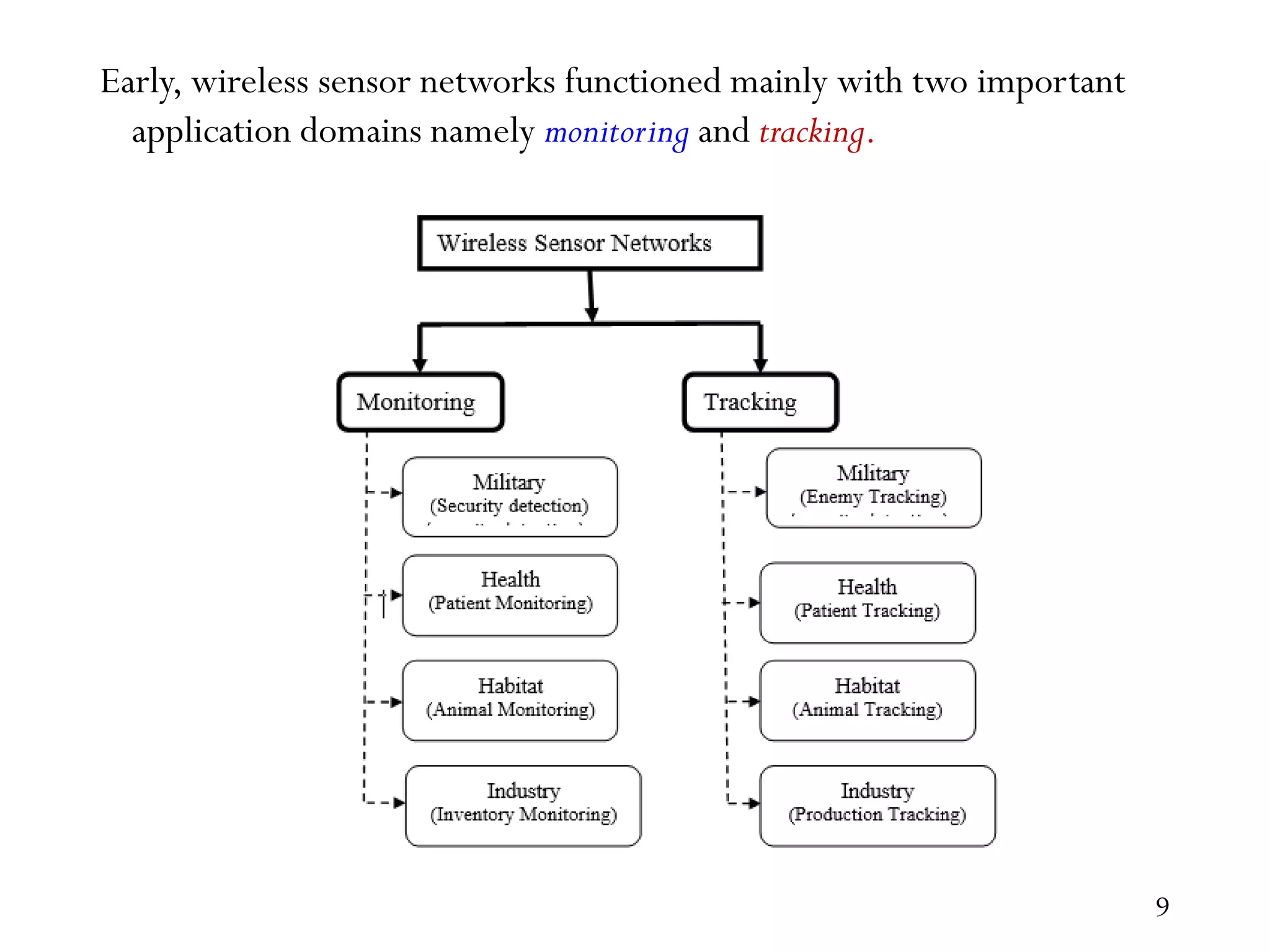
Early, wireless sensornetworks functioned mainly with two important application domains namely monitoring and tracking. 9
10.
One Minute Paper •List fewApplications ofWSNs – you are familiar with 10
11.
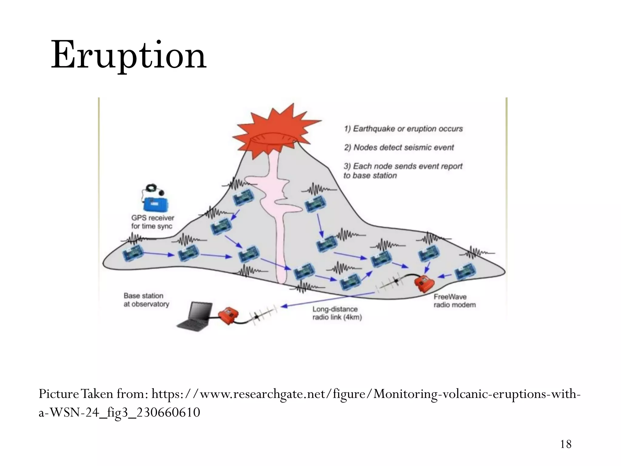
Wireless Sensor Networks Applications •Forest fire detection • Air pollution monitoring • Water quality monitoring • Land slide detection • Automotive application • Military application • Animal Habitat Monitoring &Tracking • Agriculture • Health Care Monitoring 11
12.
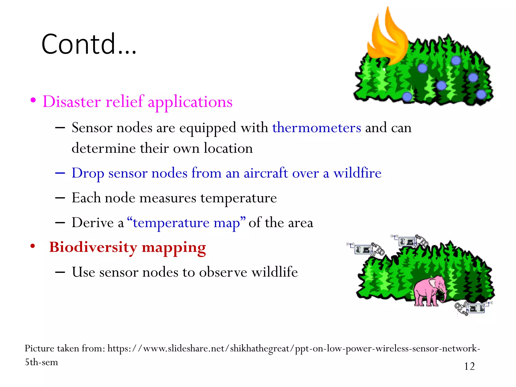
Contd… • Disaster reliefapplications – Sensor nodes are equipped with thermometers and can determine their own location – Drop sensor nodes from an aircraft over a wildfire – Each node measures temperature – Derive a “temperature map” of the area • Biodiversity mapping – Use sensor nodes to observe wildlife Picture taken from: https://www.slideshare.net/shikhathegreat/ppt-on-low-power-wireless-sensor-network- 5th-sem 12
13.
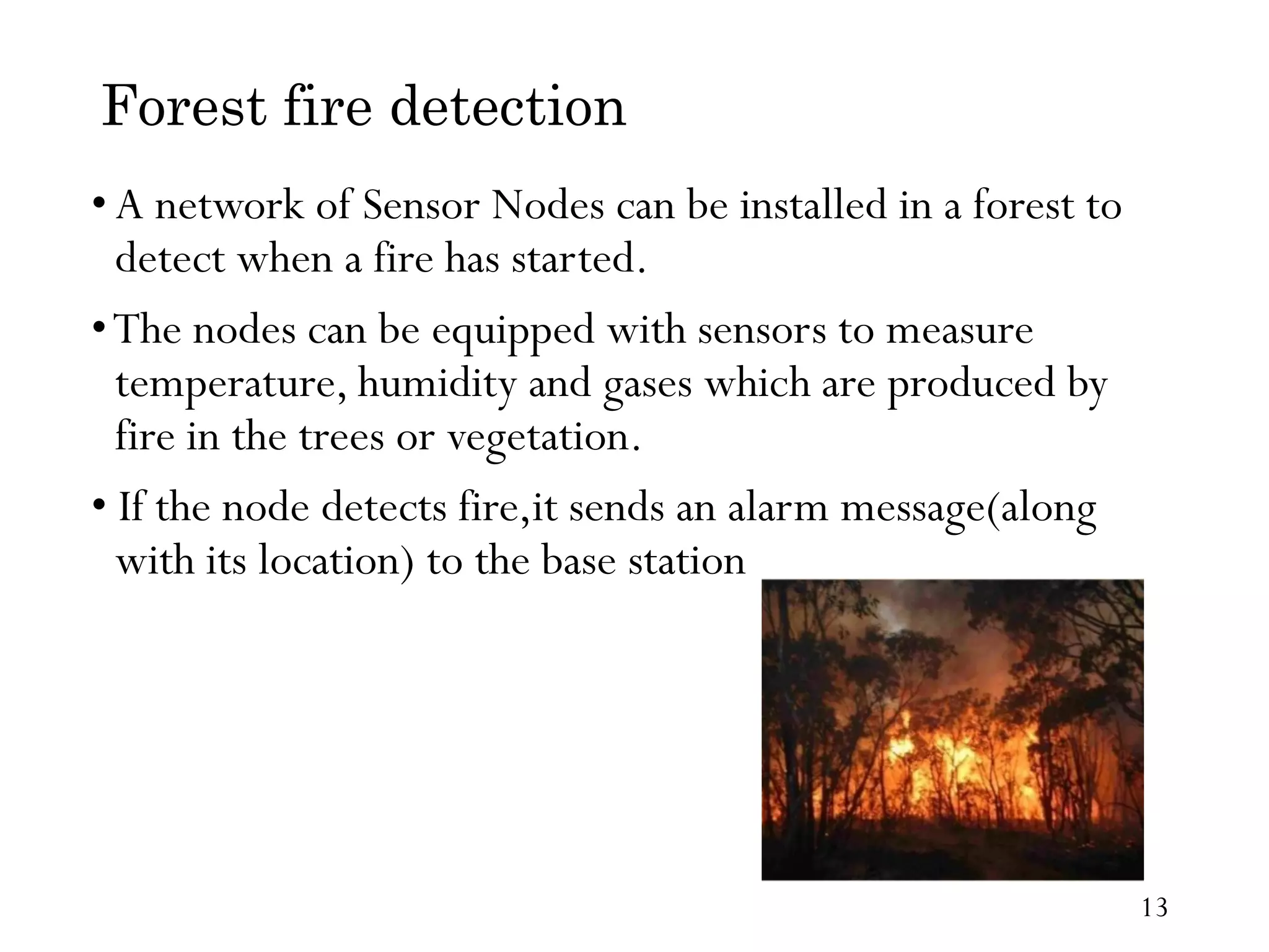
Forest fire detection •Anetwork of Sensor Nodes can be installed in a forest to detect when a fire has started. •The nodes can be equipped with sensors to measure temperature, humidity and gases which are produced by fire in the trees or vegetation. • If the node detects fire,it sends an alarm message(along with its location) to the base station 13
14.
Air Quality monitoring •Traditional air quality monitoring methods, such as building air quality monitoring stations, are typically expensive. • The solution to these is air quality monitoring system based on the technology of wireless sensor networks (WSNs). • Wireless sensor networks have been deployed in several cities to monitor the concentration of dangerous gases for citizens. 14
15.
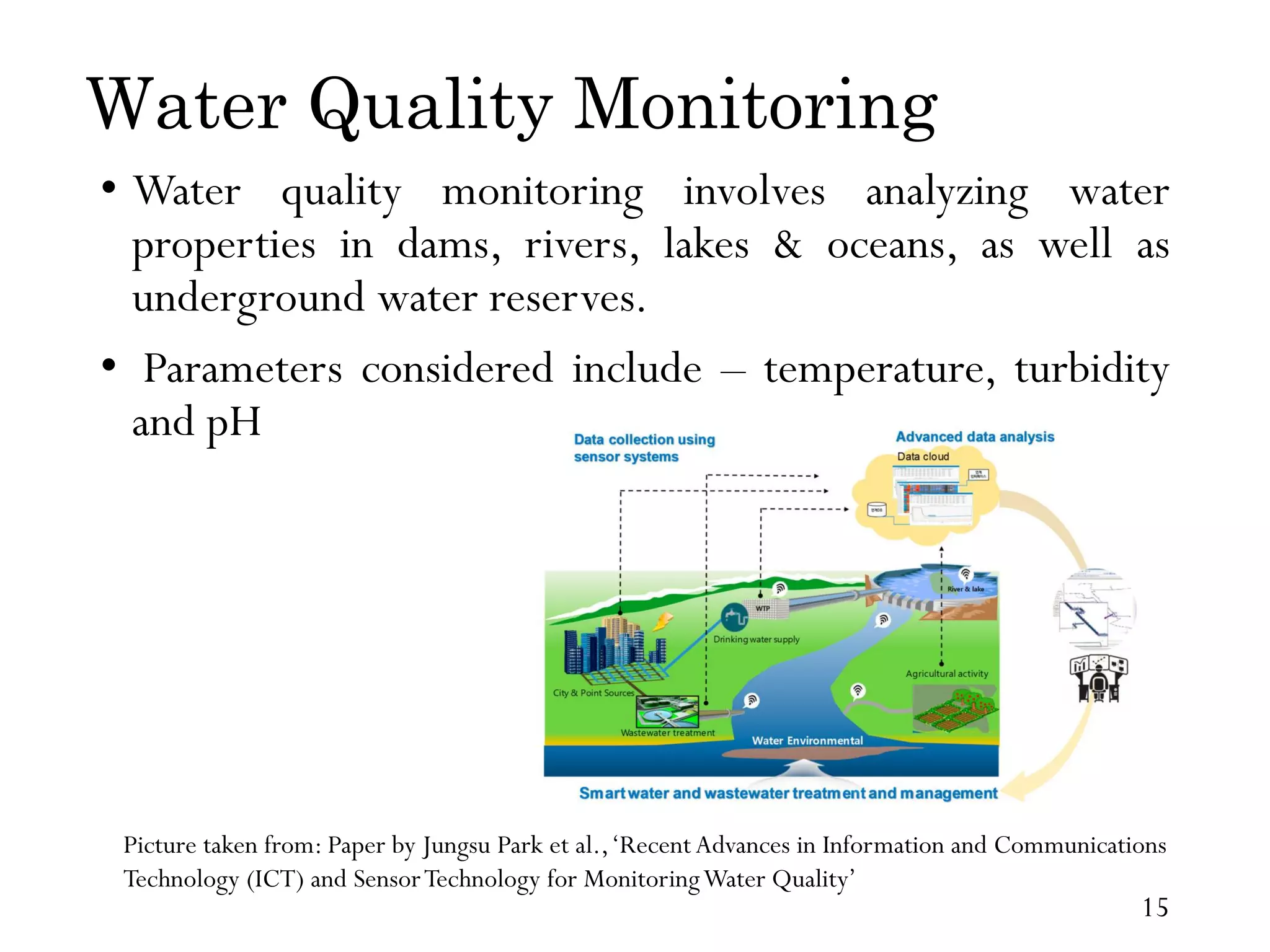
Water Quality Monitoring •Water quality monitoring involves analyzing water properties in dams, rivers, lakes & oceans, as well as underground water reserves. • Parameters considered include – temperature, turbidity and pH Picture taken from: Paper by Jungsu Park et al.,‘Recent Advances in Information and Communications Technology (ICT) and SensorTechnology for MonitoringWater Quality’ 15
16.
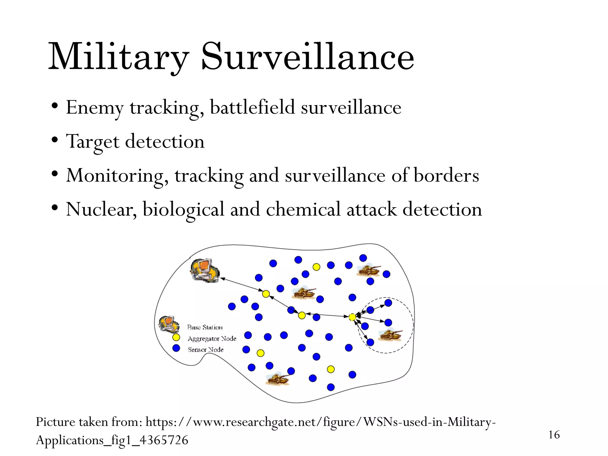
Military Surveillance • Enemytracking, battlefield surveillance • Target detection • Monitoring, tracking and surveillance of borders • Nuclear, biological and chemical attack detection Picture taken from: https://www.researchgate.net/figure/WSNs-used-in-Military- Applications_fig1_4365726 16
17.
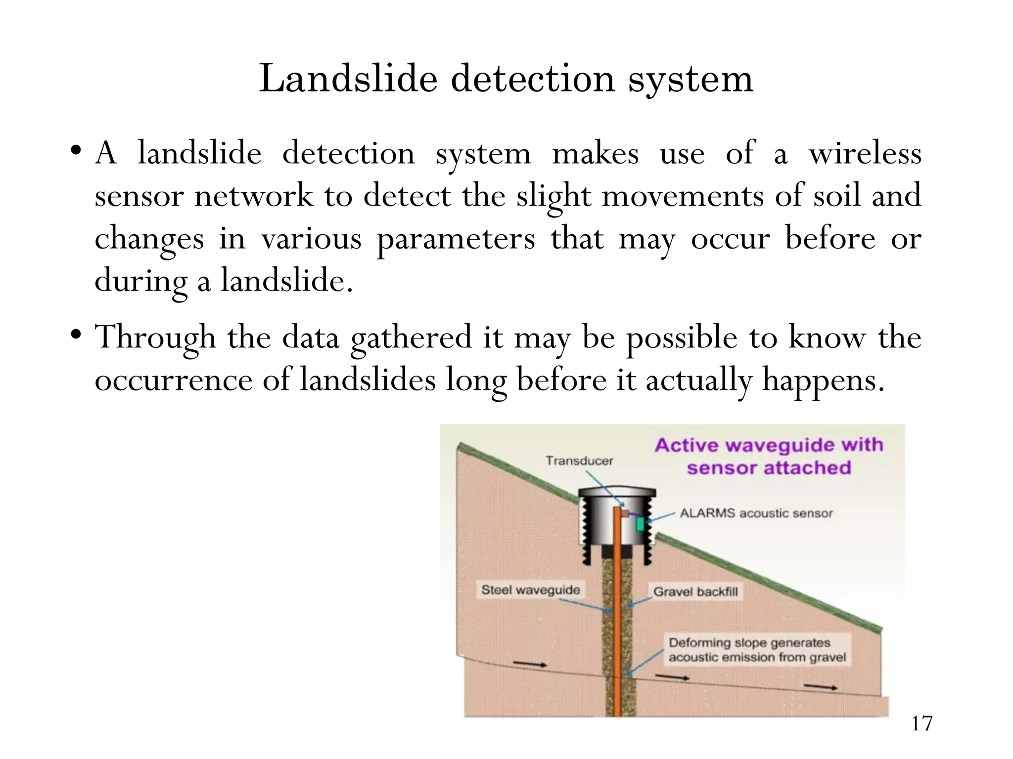
Landslide detection system •A landslide detection system makes use of a wireless sensor network to detect the slight movements of soil and changes in various parameters that may occur before or during a landslide. • Through the data gathered it may be possible to know the occurrence of landslides long before it actually happens. 17
Precision Agriculture PictureTaken from:Articleby uferah safri et al,‘PrecisionAgricultureTechniques and Practices: From Considerations toApplications’ – Bring out fertilizer/pesticides/irrigation only where needed 19
20.
Medical & HealthCare Monitoring Picture taken from: https://www.slideshare.net/DeeptimanMallick/using-tiny-os-in- wireless-sensor-network – Post-operative or intensive care – Long-term surveillance of chronically ill patients or the elderly 20
21.
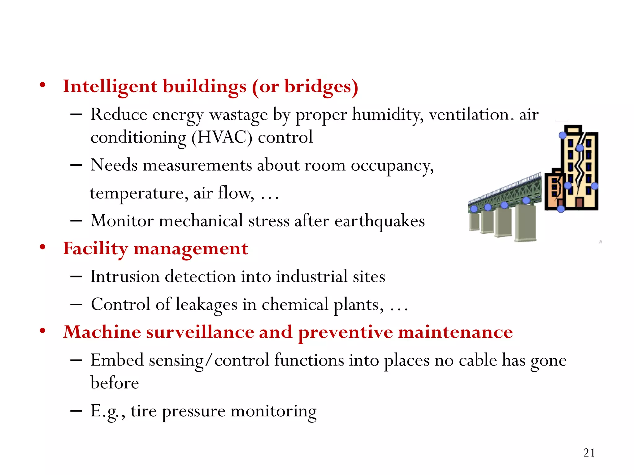
• Intelligent buildings(or bridges) – Reduce energy wastage by proper humidity, ventilation, air conditioning (HVAC) control – Needs measurements about room occupancy, temperature, air flow, … – Monitor mechanical stress after earthquakes • Facility management – Intrusion detection into industrial sites – Control of leakages in chemical plants, … • Machine surveillance and preventive maintenance – Embed sensing/control functions into places no cable has gone before – E.g., tire pressure monitoring 21
22.
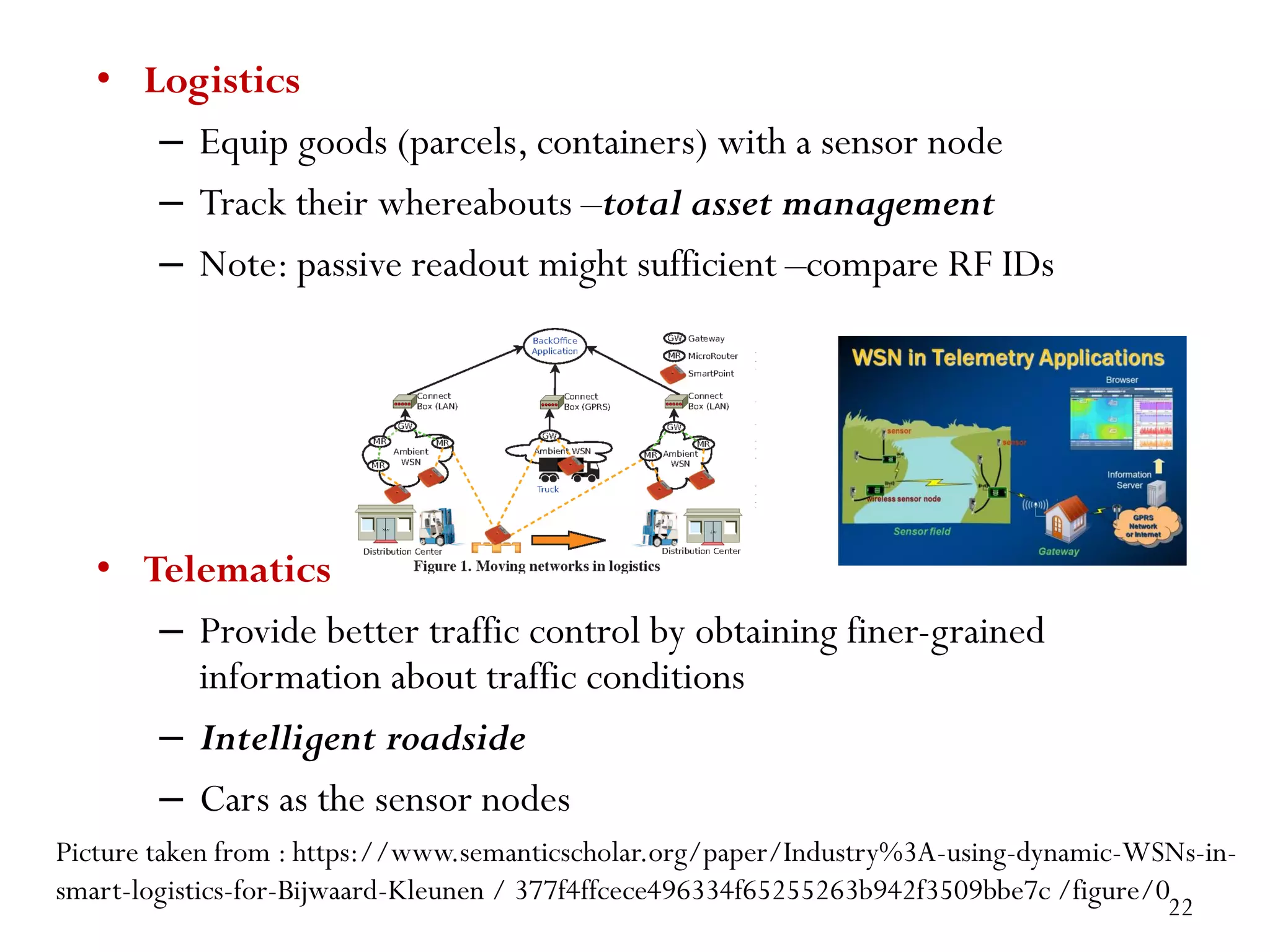
• Logistics – Equipgoods (parcels, containers) with a sensor node – Track their whereabouts –total asset management – Note: passive readout might sufficient –compare RF IDs • Telematics – Provide better traffic control by obtaining finer-grained information about traffic conditions – Intelligent roadside – Cars as the sensor nodes Picture taken from : https://www.semanticscholar.org/paper/Industry%3A-using-dynamic-WSNs-in- smart-logistics-for-Bijwaard-Kleunen / 377f4ffcece496334f65255263b942f3509bbe7c /figure/0 22
How are sensornodes deployed in their environment? • Dropped from aircraft ! Random deployment – Usually uniform random distribution for nodes over finite area is assumed – Is that a likely proposition? • Well planned, fixed ! Regular deployment – E.g., in preventive maintenance or similar – Not necessarily geometric structure, but that is often a convenient assumption Deployment options for WSN 24
25.
• Mobile sensornodes – Can move to compensate for deployment shortcomings – Can be passively moved around by some external force (wind, water) – Can actively seek out “interesting” areas Maintenance options • Feasible and/or practical to maintain sensor nodes? – E.g., to replace batteries? – Or: unattended operation? – Impossible but not relevant? Mission lifetime might be very small • Energy supply? – Limited from point of deployment? – Some form of recharging, energy scavenging from environment? – E.g., solar cells 25
26.
Assignment • Explain anyone application ofWSN (Agriculture, Medical, Military, Under water,Animal Habitat, IOT, IIOT etc..) in Detail – What isWSN? – Type of Sensor Used – Application in Detail – Working – Refernces 26
Design Challenges inWSN • Heterogeneity – The devices deployed may be of various types and need to collaborate with each other. • Distributed Processing – The algorithms need to be centralized as the processing is carried out on different nodes. • Low Bandwidth Communication – The data should be transferred efficiently between sensors • Large Scale Coordination – The sensors need to coordinate with each other to produce required results. 28
29.
Contd… • Utilization ofSensors – The sensors should be utilized in a ways that produce the maximum performance and use less energy. • RealTime Computation – The computation should be done quickly as new data is always being generated. 29
30.
Challenges for WSNs •Type of service ofWSN – Not simply moving bits like another network – Rather: provide answers(not just numbers) – Issues like geographic scoping are natural requirements, absent from other networks • Quality of service – Traditional QoS metrics do not apply – Still, service of WSN must be “good”: Right answers at the right time • Fault tolerance – Be robust against node failure (running out of energy, physical destruction, …) 30
31.
Contd.. • Lifetime – Thenetwork should fulfill its task as long as possible – definition depends on application – Lifetime of individual nodes relatively unimportant – But often treated equivalently • Scalability – Support large number of nodes • Wide range of densities – Vast or small number of nodes per unit area, very application-dependent 31
32.
Contd.. • Programmability – Re-programmingof nodes in the field might be necessary, improve flexibility • Maintainability – WSN has to adapt to changes, self-monitoring, adapt operation – Incorporate possible additional resources, e.g., newly deployed nodes 32
33.
Operational Challenges ofWireless Sensor Networks • Energy Efficiency • Limited storage and computation • Low bandwidth and high error rates • Errors are common – Wireless communication – Noisy measurements – Node failure are expected • Scalability to a large number of sensor nodes • Survivability in harsh environments • Experiments are time- and space-intensive 33
34.
Required mechanisms tomeet requirements • Multi-hop wireless communication • Energy-efficient operation – Both for communication and computation, sensing, actuating • Auto-configuration – Manual configuration just not an option • Collaboration & in-network processing – Nodes in the network collaborate towards a joint goal – Pre-processing data in network (as opposed to at the edge) can greatly improve efficiency 34
35.
Contd.. • Data centricnetworking – Focusing network design on data, not on node identifies(id- centric networking) – To improve efficiency • Locality – Do things locally (on node or among nearby neighbors) as far as possible • Exploit tradeoffs – E.g., between invested energy and accuracy 35
36.
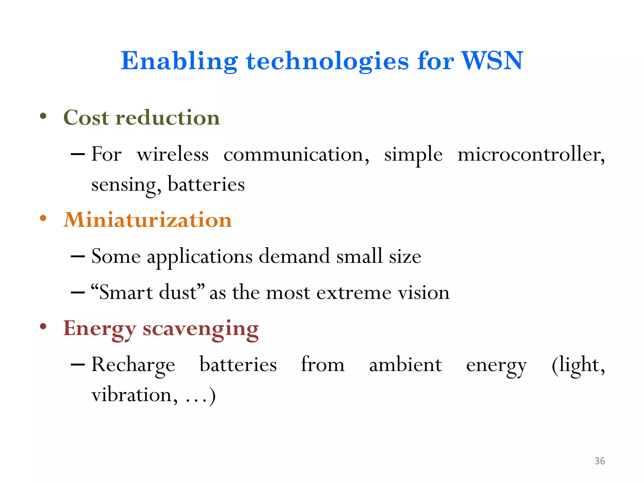
Enabling technologies forWSN • Cost reduction – For wireless communication, simple microcontroller, sensing, batteries • Miniaturization – Some applications demand small size – “Smart dust” as the most extreme vision • Energy scavenging – Recharge batteries from ambient energy (light, vibration, …) 36
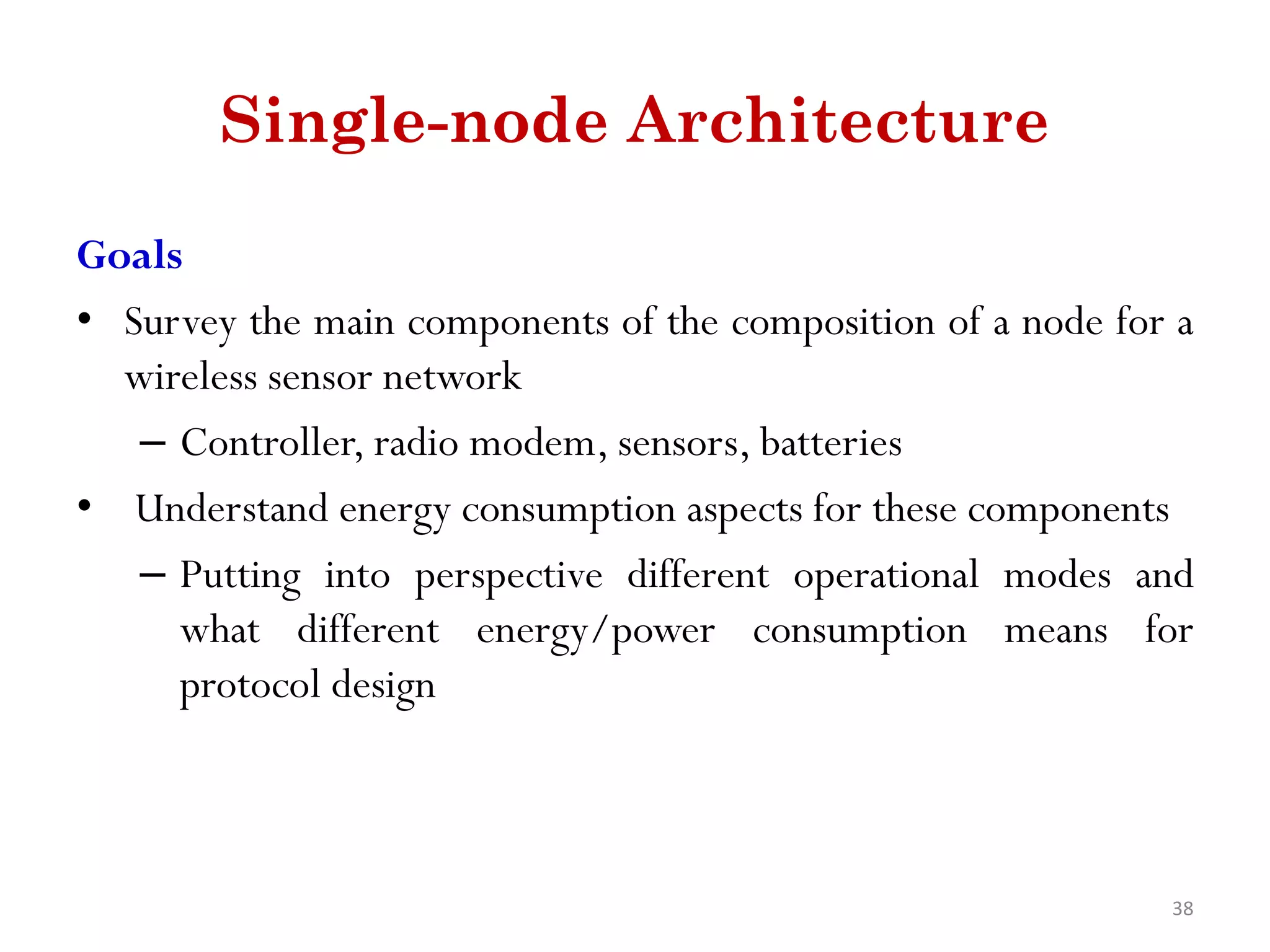
Single-node Architecture Goals • Surveythe main components of the composition of a node for a wireless sensor network – Controller, radio modem, sensors, batteries • Understand energy consumption aspects for these components – Putting into perspective different operational modes and what different energy/power consumption means for protocol design 38
39.
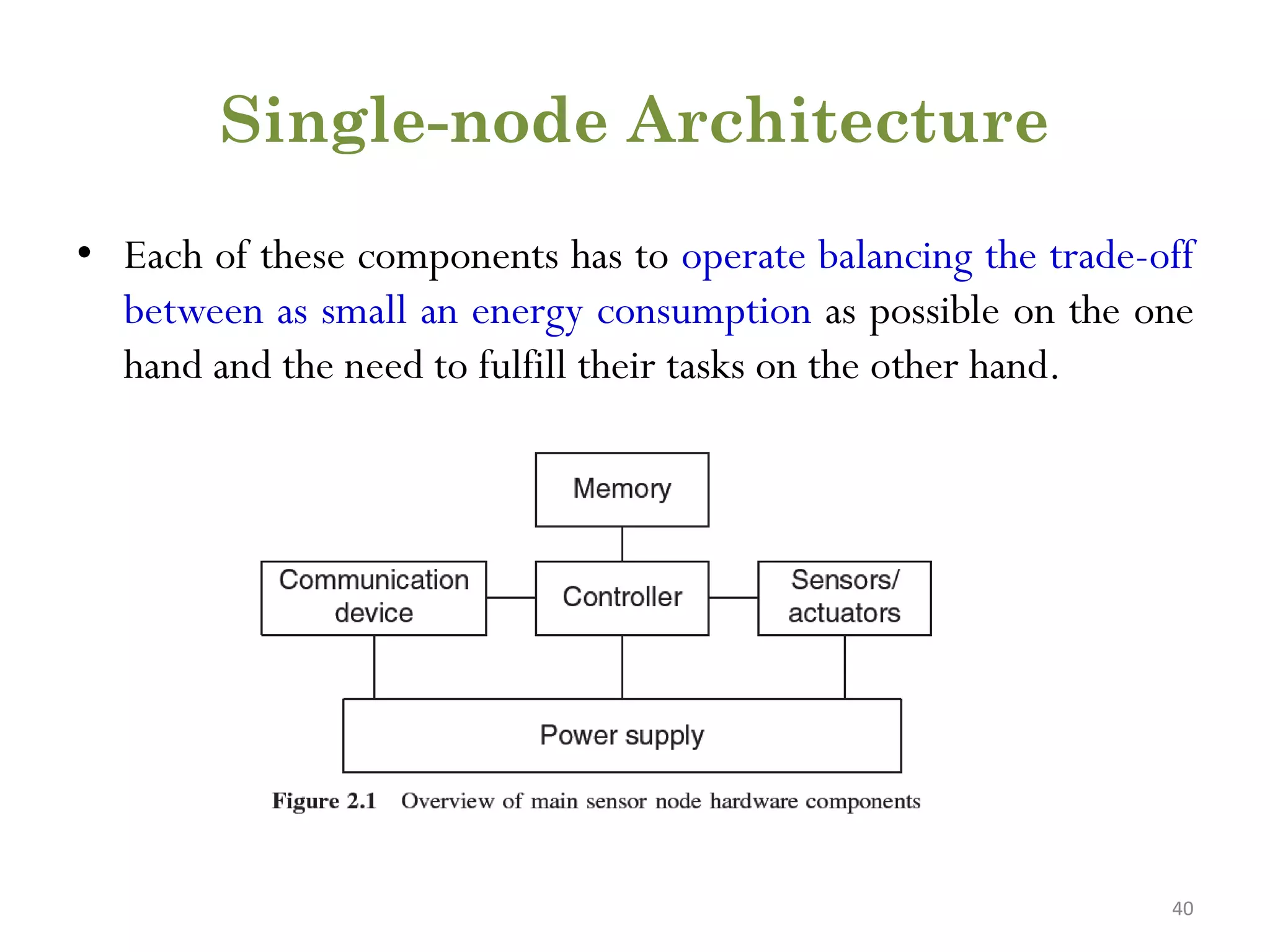
Main components ofa WSN node • Controller - A controller to process all the relevant data, capable of executing arbitrary code. • Memory - Some memory to store programs and intermediate data; usually, different types of memory are used for programs and data. • Communication device(s) - Turning nodes into a network requires a device for sending and receiving information over a wireless channel • Sensors/actuators - The actual interface to the physical world: devices that can observe or control physical parameters of the environment • Power supply - As usually no tethered power supply is available, some form of batteries are necessary to provide energy. Sometimes, some form of recharging by obtaining energy from the environment is available as well (e.g. solar cells). 39
40.
Single-node Architecture • Eachof these components has to operate balancing the trade-off between as small an energy consumption as possible on the one hand and the need to fulfill their tasks on the other hand. 40
41.
Controller Main options: • Generalpurpose processor – Used in Desktop Computers – Highly over powered – Energy Consumption is excessive • Micro controller – optimized for embedded applications – Flexibility in connecting other devices – low power consumption – Build in Memory – Freely programmable and flexible – Going to Sleep State 41
42.
Controller Main options: • DSPs –optimized for signal processing tasks – Advantages are not suitable here • FPGAs (Field –Programmable GateArrays) – may be good for testing – Reprogrammed • ASICs – Specialized processor – Custom Design for application – only when peak performance is needed, no flexibility 42
43.
Controller Example microcontrollers • IntelstrongARM – High end Processor with PDAs – SA-1100 model has 32 bit reduced Instruction Set Computer (RISC) core, running at up to 206 MHz • Texas Instruments MSP430 – 16-bit RISC core, up to 4 MHz, versions with 2-10 kbytes RAM, several DACs, RT clock, prices start at 0.49 US$ • AtmelATMega – 8-bit controller – Usage in embedded application with external interfaces. 43
Memory • The memorycomponent is fairly straightforward. – Need for RandomAccess Memory (RAM) to store intermediate sensor readings, packets from other nodes. – While RAM is fast, disadvantage - loses its content if power supply is interrupted. • Program code can be stored in – Read-Only Memory (ROM) – Electrically Erasable Programmable Read-Only Memory (EEPROM) or – flash memory 45
46.
Contd… • Flash memoryserve as intermediate storage of data in case RAM is insufficient or when the power supply of RAM shut down for some time. • The long read and write access delays of flash memory need high energy. • Manufacturing costs and power consumption. • Memory requirements are very much application dependent. 46
47.
Communication Devices • Choiceof transmission medium • Transceivers • Transceivers tasks and characteristics • Transceiver structure • Transceiver operational states • Advanced Radio Concepts • Nonradio frequency wireless communication • Examples of radio transceivers 47
48.
Choice of transmissionmedium • The communication device is used to exchange data between individual nodes. • wired communication can actually be the method of choice and is frequently applied in many sensor network like settings (using field buses like Profibus, LON, CAN, or others). • The first choice to make is that of the transmission medium – Radio frequencies – Optical communication – Ultrasound – other media like magnetic inductance are only used in very specific cases 48
49.
Contd.. • Radio Frequency(RF)-based communication - best fits the requirements of mostWSN applications – It provides relatively long range and high data rates – acceptable error rates at reasonable energy expenditure – does not require line of sight between sender and receiver • Wireless sensor networks typically use communication frequencies between about 433 MHz and 2.4 GHz. 49 Picture taken from: https://www.britannica.com/science/radio-frequency-spectrum
50.
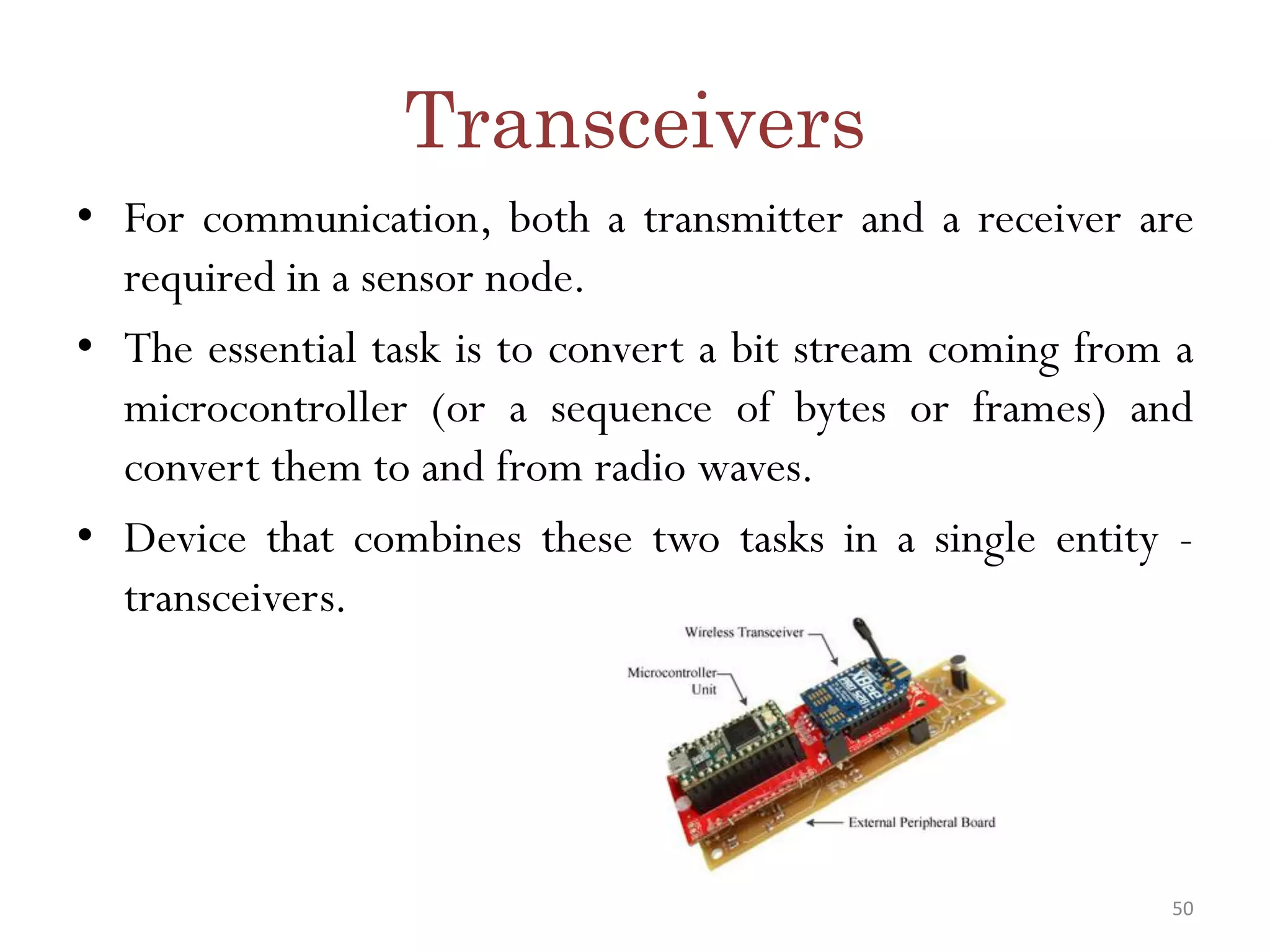
Transceivers • For communication,both a transmitter and a receiver are required in a sensor node. • The essential task is to convert a bit stream coming from a microcontroller (or a sequence of bytes or frames) and convert them to and from radio waves. • Device that combines these two tasks in a single entity - transceivers. 50
51.
Contd… • Half-duplex operationis realized • A range of low-cost transceivers is commercially available that incorporate all the circuitry required for transmitting and receiving – modulation, demodulation, amplifiers, filters, mixers etc 51
52.
Transceiver tasks andcharacteristics • Service to upper layer – A receiver has to offer certain services to the upper layers, most notably to the MediumAccess Control (MAC) layer. – This service is packet oriented; sometimes, – Transceiver only provides a byte interface or even only a bit interface to the microcontroller. • Power consumption and energy efficiency – The simplest interpretation of energy efficiency is the energy required to transmit and receive a single bit. – Transceivers should be switchable between different states - active and sleeping. 52
53.
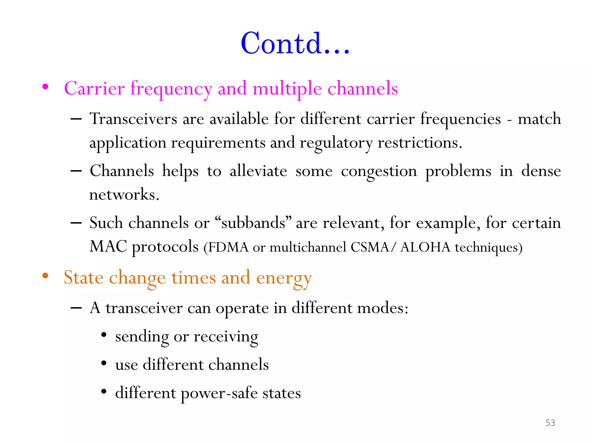
Contd… • Carrier frequencyand multiple channels – Transceivers are available for different carrier frequencies - match application requirements and regulatory restrictions. – Channels helps to alleviate some congestion problems in dense networks. – Such channels or “subbands” are relevant, for example, for certain MAC protocols (FDMA or multichannel CSMA/ALOHA techniques) • State change times and energy – A transceiver can operate in different modes: • sending or receiving • use different channels • different power-safe states 53
54.
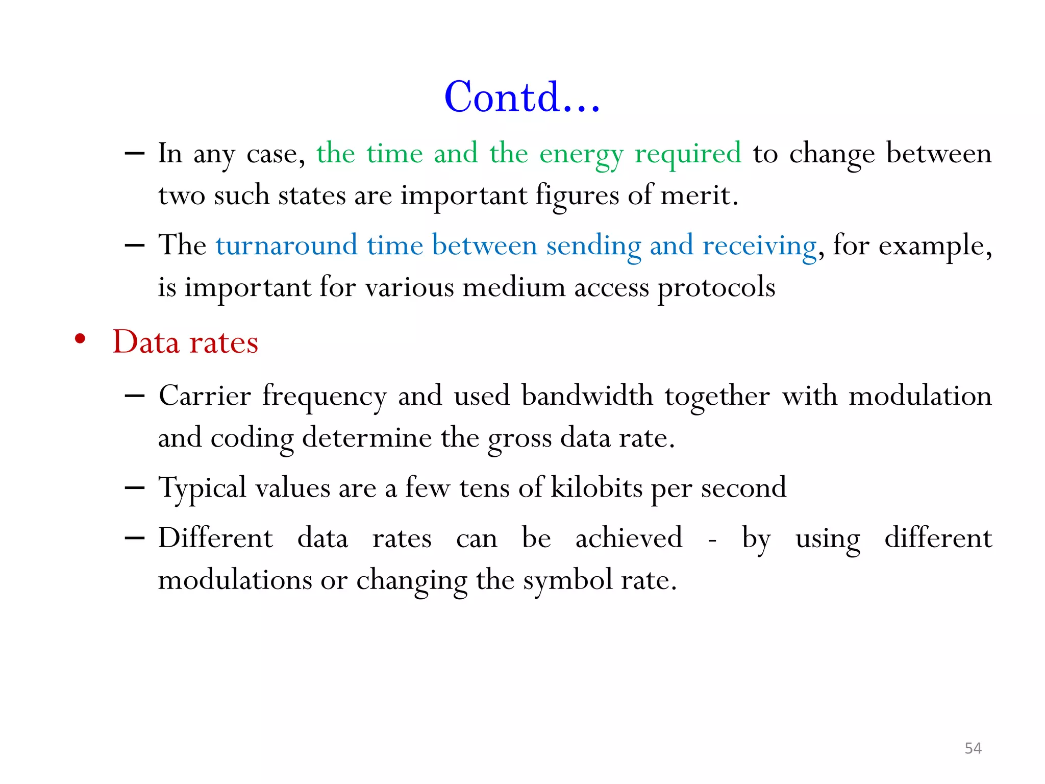
Contd… – In anycase, the time and the energy required to change between two such states are important figures of merit. – The turnaround time between sending and receiving, for example, is important for various medium access protocols • Data rates – Carrier frequency and used bandwidth together with modulation and coding determine the gross data rate. – Typical values are a few tens of kilobits per second – Different data rates can be achieved - by using different modulations or changing the symbol rate. 54
55.
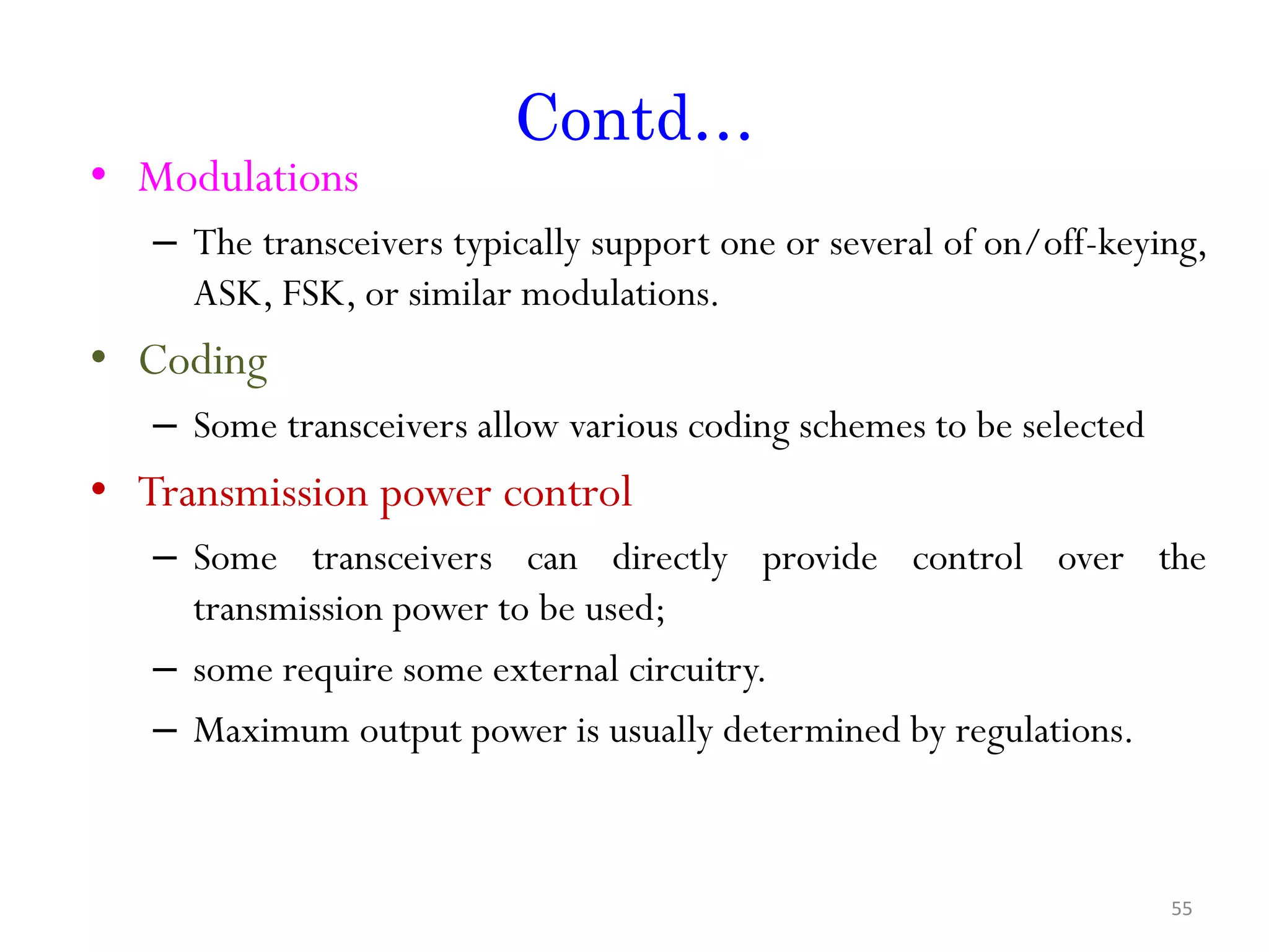
Contd… • Modulations – Thetransceivers typically support one or several of on/off-keying, ASK, FSK, or similar modulations. • Coding – Some transceivers allow various coding schemes to be selected • Transmission power control – Some transceivers can directly provide control over the transmission power to be used; – some require some external circuitry. – Maximum output power is usually determined by regulations. 55
56.
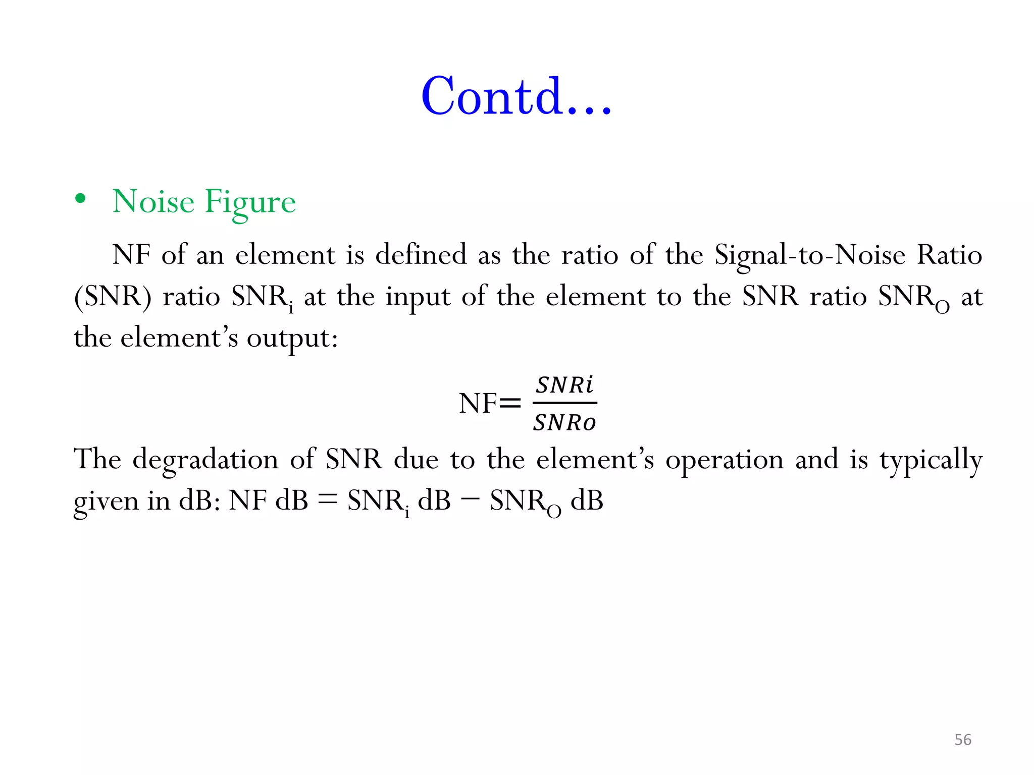
Contd… • Noise Figure NFof an element is defined as the ratio of the Signal-to-Noise Ratio (SNR) ratio SNRi at the input of the element to the SNR ratio SNRO at the element’s output: NF= 𝑆𝑁𝑅𝑖 𝑆𝑁𝑅𝑜 The degradation of SNR due to the element’s operation and is typically given in dB: NF dB = SNRi dB − SNRO dB 56
57.
Contd… • Gain – Thegain is the ratio of the output signal power to the input signal power and is typically given in dB. – Amplifiers with high gain are desirable to achieve good energy efficiency. • Power efficiency – The efficiency of the radio front end is given as the ratio of the radiated power to the overall power consumed by the front end – power amplifier, the efficiency describes the ratio of the output signal’s power to the power consumed by the overall power amplifier. • Receiver sensitivity – The receiver sensitivity (given in dBm) is the minimum signal power at the receiver needed to achieve a prescribed Eb/N0 – Better sensitivity levels extend the possible range of a system. 57
58.
Contd… • Range – Therange is considered in absence of interference; it evidently depends on the maximum transmission power, on the antenna characteristics, on the attenuation caused by the environment, which in turn depends on the used carrier frequency, on the modulation/coding scheme that is used, and on the bit error rate that one is willing to accept at the receiver. – It also depends on the quality of the receiver – based on sensitivity. – The products with ranges between a few meters and several hundreds of meters are available 58
59.
Contd… • Blocking performance –The blocking performance of a receiver is its achieved bit error rate in the presence of an interferer. – Blocking performance can be improved by interposing a filter between antenna and transceiver. – An important special case is an adjacent channel interferer that transmits on neighboring frequencies. – The adjacent channel suppression describes a transceiver’s capability to filter out signals from adjacent frequency bands (and thus to reduce adjacent channel interference) has a direct impact on the observed Signal to Interference and Noise Ratio (SINR). 59
60.
Contd… • Out ofband emission – The inverse to adjacent channel suppression is the out of band emission of a transmitter. – To limit disturbance of other systems, or of the WSN itself in a multichannel setup, the transmitter should produce little transmission power • Carrier sense and RSSI – The precise semantics of this carrier sense signal depends on the implementation. – For example, the IEEE 802.15.4 standard [468] distinguishes the following modes: 60
61.
Contd.. • A carrierhas been detected, that is, some signal which complies with the modulation. • Carrier detected and energy is present. • The signal strength at which an incoming data packet has been received can provide useful information (e.g. a rough estimate about the distance from the transmitter assuming the transmission power is known); • A receiver has to provide this information in the Received Signal Strength Indicator (RSSI). 61
62.
Contd.. • Frequency Stability –The frequency stability denotes the degree of variation from nominal center frequencies when environmental conditions of oscillators like temperature or pressure change – Poor frequency stability can break down communication links • Voltage range – Transceivers should operate reliably over a range of supply voltages – Inefficient voltage stabilization circuitry is required 62
63.
Transceiver structures • Radiofrequency front end – Performs Analog signal processing in the actual radio frequency band • Baseband Processor – Performs all Signal Processing in digital domain – Communicates with a sensor node processor or other digital circuitry Between these two parts a frequency conversion constituted by DACs and ADCs 63
64.
• The PowerAmplifier (PA) accepts upconverted signals from the IF or baseband part and amplifies them for transmission over the antenna. The Low Noise Amplifier (LNA) amplifies incoming signals up to levels suitable for further processing without significantly reducing the SNR [470]. 64
65.
• The rangeof powers of the incoming signals varies from very weak signals from nodes close to the reception boundary to strong signals from nearby nodes; this range can be up to 100 dB. • LNA is active all the time and can consume a significant fraction of the transceiver’s energy. • Elements like local oscillators or voltage-controlled oscillators and mixers are used for frequency conversion from the RF spectrum to IF or to the baseband. • The incoming signal at RF frequencies fRF is multiplied in a mixer with a fixed-frequency signal from the local oscillator (frequency fLO). • IF = fLO − fRF. 65
66.
Transceiver Operational States •Transmit State: – In the transmit state, the transmit part of the transceiver is active and the antenna radiates energy. • Receive State: – the receive part is active. • Idle State: – A transceiver that is ready to receive but is not currently receiving anything is said to be in an idle state. – many parts of the receive circuitry are active, and others can be switched off. 66
67.
Contd.. – For example,in the synchronization circuitry, some elements concerned with acquisition are active, while those concerned with tracking can be switched off and activated only when the acquisition has found something. – A major source of power dissipation is leakage. • Sleep State: – significant parts of the transceiver are switched off. – There are transceivers offering several different sleep states. – These sleep states differ in the amount of circuitry switched off – associated recovery times and startup energy 67
Advanced Radio Concepts –Wake up radio • One of the most power-intensive operations is waiting for a transmission to come in, ready to receive it. • During this time, the receiver circuit must be powered up - to observe wireless channel needs spending energy without any immediate benefit. • A receiver structure is necessary that does not need power but can detect when a packet starts to arrive. • To keep this specialized receiver simple, it should raise an event to notify other components of an incoming packet; upon such an event, the main receiver can be turned on and perform the actual reception of the packet. • Such receiver concepts are called wakeup receivers • Each packet – power consumption is 1 microwatt 69
70.
Contd… – Spread spectrumtransceivers • ASK, FSK has limited Performance when lot of interference. • To overcome Spread spectrum transceivers – DSSS (Direct Sequence spread spectrum, Frequency Hopping Spread Spectrum • Complex hardware and costly – Ultraband communication • Using such a large bandwidth, an ultra wideband communication will overlap with the spectrum of a conventional radio system. • But, because of the large spreading of the signal, a very small transmission power suffices UWB transmitter is actually relatively simple since it does not need oscillators or related circuitry found in transmitters for a carrier-frequency-based transmitter. • The receivers require complex timing synchronization. 70
71.
Non radio frequencywireless communication – Optical – Optical link between sensors – Advantage – very small energy per bit – LEDs – High efficiency senders – Disadvantages: Strongly influenced by whether condition – Line of Sight – Ultra sound – For underwater communication: Ultra sound communication is suitable – Travels for long distances – Different propagation speed 71
72.
Examples of radioTransceiver – RFMTR1000 family – Hardware accelerators (Mica motes) – Chipcon CC100 and CC2420 family – InfineonTDA 525x family – IEEE802.15.4/Ember EM2420 RFTransceiver – National Semiconductor LMX3162 – Conexant RDSSS9M 72
73.
Contd.. – RFMTR1000 family •The TR1000 family of radio transceivers from RF Monolithics2 is available for the 916 MHz and 868 MHz frequency range. • It works in a 400 kHz wide band centered at, for example, 916.50 MHz. • It is intended for short-range radio communication with up to 115.2 kbps. • Low-power consumption in both send and receive modes and especially in sleep mode. 73
74.
Contd.. – Hardware accelerators(Mica motes) • The Mica motes use the RFM TR1000 transceiver and contain also a set of hardware accelerators. • The transceiver offers a very low-level interface, giving the microcontroller tight control over frame formats, MAC protocols, and so forth. • On the other hand, framing and MAC can be very computation intensive, for example, for computing checksums, for making bytes out of serially received bits or for detecting Start Frame Delimiters (SFDs) in a stream of symbols 74
75.
• ChipconCC1000 – Range300 to 1000 MHz, programmable in 250 Hz steps – FSK modulation – Provides RSSI • ChipconCC 2400 – Implements 802.15.4 – 2.4 GHz, DSSS modem – 250 kbps – low power consumption than above transceivers
76.
• InfineonTDA 525xfamily – provides flexible, single-chip, energy-efficient transceivers – E.g.,TDA5250: 868 -870 MHz transceiver – ASK or FSK modulation – RSSI, highly efficient power amplifier – Intelligent power down,“self-polling” mechanism(define data rate) – Excellent blocking performance (quite resistant to interference)
77.
Example radio transceiversfor ad hoc networks • Ad hoc networks: Usually, higher data rates are required • Typical: IEEE 802.11 b/g/a is considered – Up to 54 MBit/s – Relatively long distance (100s of meters possible, typical 10s of meters at higher data rates) – Works reasonably well (but certainly not perfect) in mobile environments – Problem: expensive equipment, quite power hungry
Contd… • Sensors – Sensorscan be roughly categorized into three categories • Passive, omnidirectional sensors – These sensors can measure a physical quantity at the point of the sensor node without actually manipulating the environment by active probing – in this sense, they are passive. – Moreover, some of these sensors actually are self-powered in the sense that they obtain the energy they need from the environment – energy is only needed to amplify their analog signal. There is no notion of “direction” involved in these measurements.
80.
Contd… – Typical examplesfor such sensors include thermometer, light sensors, vibration, microphones, humidity, mechanical stress or tension in materials, chemical sensors sensitive for given substances, smoke detectors, air pressure, and so on. • Passive, narrow-beam sensors – These sensors are passive as well, but have a well-defined notion of direction of measurement. – A typical example is a camera, which can “take measurements” in a given direction, but has to be rotated if need be.
81.
Contd… • Active sensors –This last group of sensors actively probes the environment, for example, a sonar or radar sensor or some types of seismic sensors, which generate shock waves by small explosions. • Obvious trade-offs include accuracy, dependability, energy consumption, cost, size, and so on – all this would make a detailed discussion of individual sensors quite ineffective. • Overall, most of the theoretical work on WSNs considers passive, omnidirectional sensors.
82.
Contd… • Narrow-beam-type sensorslike cameras are used in some practical testbeds, but there is no real systematic investigation on how to control and schedule the movement of such sensors. • Each sensor node has a certain area of coverage for which it can reliably and accurately report the particular quantity that it is observing.
83.
Actuators • In principle,all that a sensor node can do is to open or close a switch or a relay or to set a value in some way. • Whether this controls a motor, a light bulb, or some other physical object is not really of concern to the way communication protocols are designed. • In a real network, however, care has to be taken to properly account for the idiosyncrasies of different actuators. • Also, it is good design practice in most embedded system applications to pair any actuator with a controlling sensor – following the principle to “never trust an actuator”
84.
Power supply ofsensor nodes • Goal: to provide as much energy as possible at smallest cost/ volume/ weight/ recharge time/longevity – InWSN, recharging may or may not be an option • Options – Primary batteries –not rechargeable – Secondary batteries –rechargeable, only makes sense in combination with some form of energy harvesting • Storing power is conventionally done using batteries. • As a rough orientation, a normal AA battery stores about 2.2–2.5 Ah at 1.5V. • Battery design is a science and industry in itself, and energy scavenging has attracted a lot of attention in research.
85.
Contd… Storing energy: Batteries •Traditional batteries – The power source of a sensor node is a battery, either nonrechargeable (“primary batteries”) or, if an energy scavenging device is present on the node, also rechargeable (“secondary batteries”). – In some form or other, batteries are electro-chemical stores for energy – the chemicals being the main determining factor of battery technology.
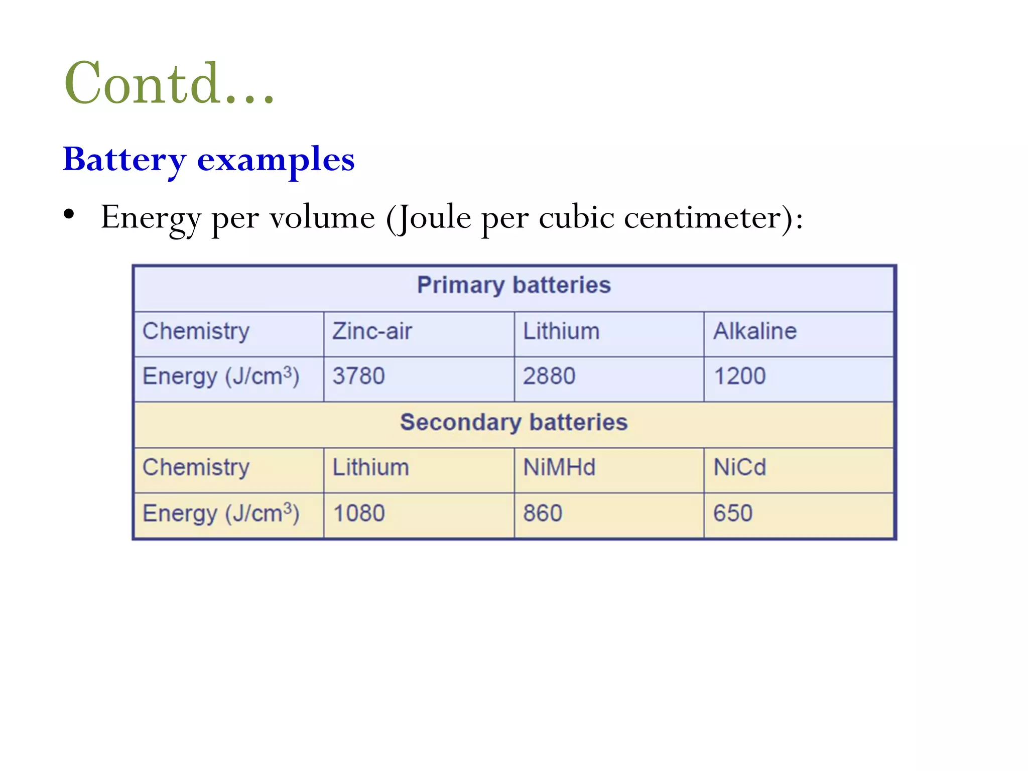
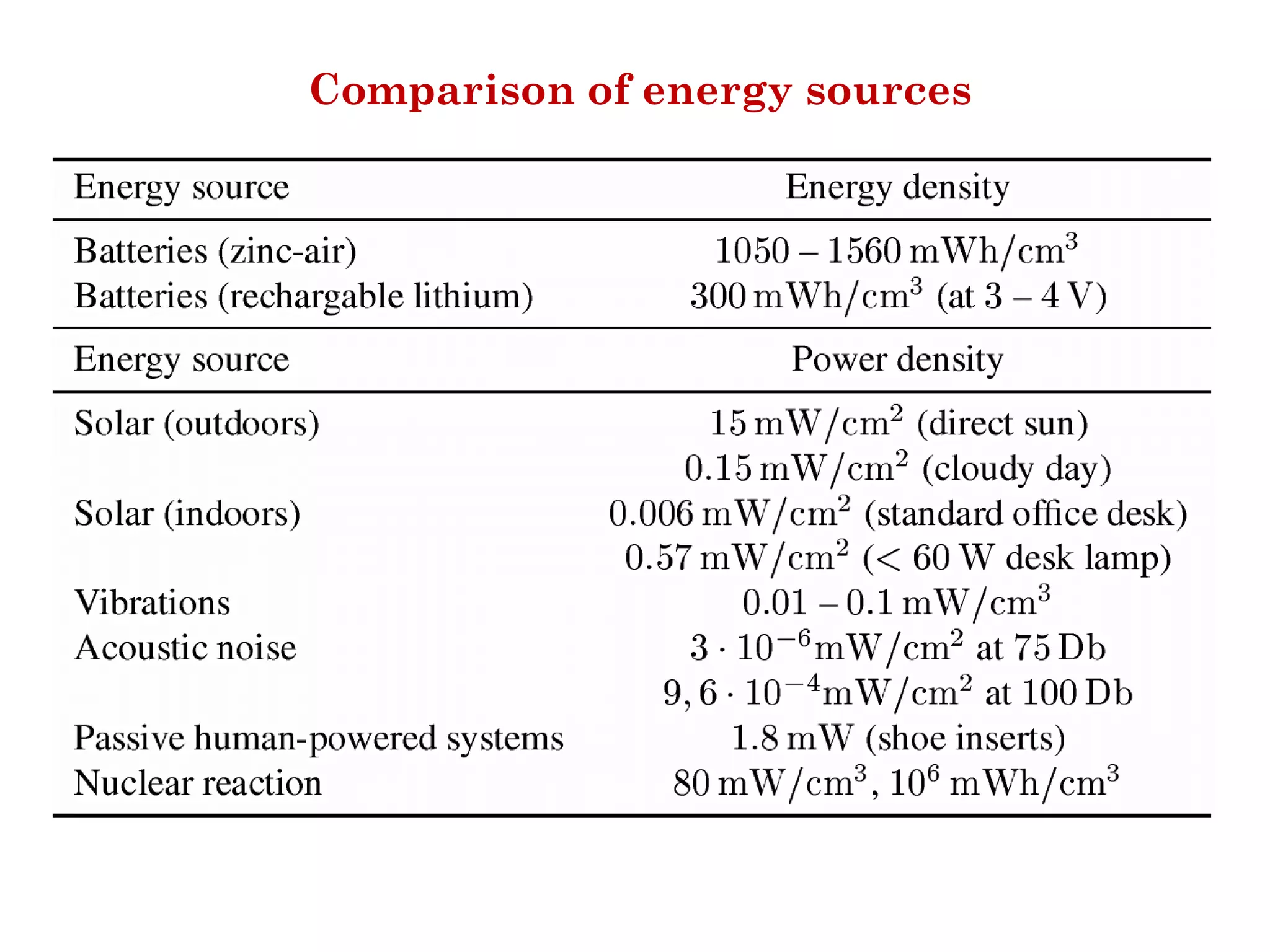
Contd… Upon these batteries,very tough requirements are imposed: Capacity • They should have high capacity at a small weight, small volume, and low price. • The main metric is energy per volume, J/cm3.Above table shows some typical values of energy densities, using traditional, macroscale battery technologies.
88.
Contd… Capacity under load •They should withstand various usage patterns as a sensor node can consume quite different levels of power over time and actually draw high current in certain operation modes. • In most technologies, the larger the battery, the more power can be delivered instantaneously. • In addition, the rated battery capacity specified by a manufacturer is only valid as long as maximum discharge currents are not exceeded, lest capacity drops or even premature battery failure occurs
89.
Contd… Self-discharge • Their self-dischargeshould be low; they might also have to last for a long time (using certain technologies, batteries are operational only for a few months, irrespective of whether power is drawn from them or not). • Zinc-air batteries, for example, have only a very short lifetime (on the order of weeks), which offsets their attractively high energy density.
90.
Contd… Efficient recharging • Rechargingshould be efficient even at low and intermittently available recharge power; consequently, the battery should also not exhibit any “memory effect”. • Some of the energy-scavenging techniques are only able to produce current in the μA region (but possibly sustained) at only a few volts at best. • Current battery technology would basically not recharge at such values.
91.
Contd… Relaxation • Their relaxationeffect – the seeming self-recharging of an empty or almost empty battery when no current is drawn from it, based on chemical diffusion processes within the cell – should be clearly understood. • Battery lifetime and usable capacity is considerably extended if this effect is leveraged. • example, it is possible to use multiple batteries in parallel and “schedule” the discharge from one battery to another, depending on relaxation properties and power requirements of the operations to be supported
92.
Contd… Energy scavenging • Someof the unconventional energy stores– fuel cells, micro heat engines, radioactivity – convert energy from some stored, secondary form into electricity in a less direct and easy to use way than a normal battery would do. • The entire energy supply is stored on the node itself – once the fuel supply is exhausted, the node fails. • To ensure truly long-lasting nodes and wireless sensor networks, such a limited energy store is unacceptable. • Rather, energy from a node’s environment must be tapped into and made available to the node – energy scavenging should take place. Several approaches exist
93.
Photovoltaics • The well-knownsolar cells can be used to power sensor nodes. • The available power depends on whether nodes are used outdoors or indoors, and on time of day and whether for outdoor usage. • Different technologies are best suited for either outdoor or indoor usage. • The resulting power is somewhere between 10 μW/cm2 indoors and 15 mW/cm2 outdoors. • Single cells achieve a fairly stable output voltage of about 0.6 V (and have therefore to be used in series) as long as the drawn current does not exceed a critical threshold, which depends, among other factors, on the light intensity. • Hence, solar cells are usually used to recharge secondary batteries.
94.
Temperature gradients • Differencesin temperature can be directly converted to electrical energy. • Theoretically, even small difference of, for example, 5 Kelvin can produce considerable power, but practical devices fall very short of theoretical upper limits (given by the Carnot efficiency). • Seebeck effect-based thermoelectric generators are commonly considered; one example is a generator, which will be commercially available soon, that achieves about 80 μW/cm2 at about 1V from a 5 Kelvin temperature difference
95.
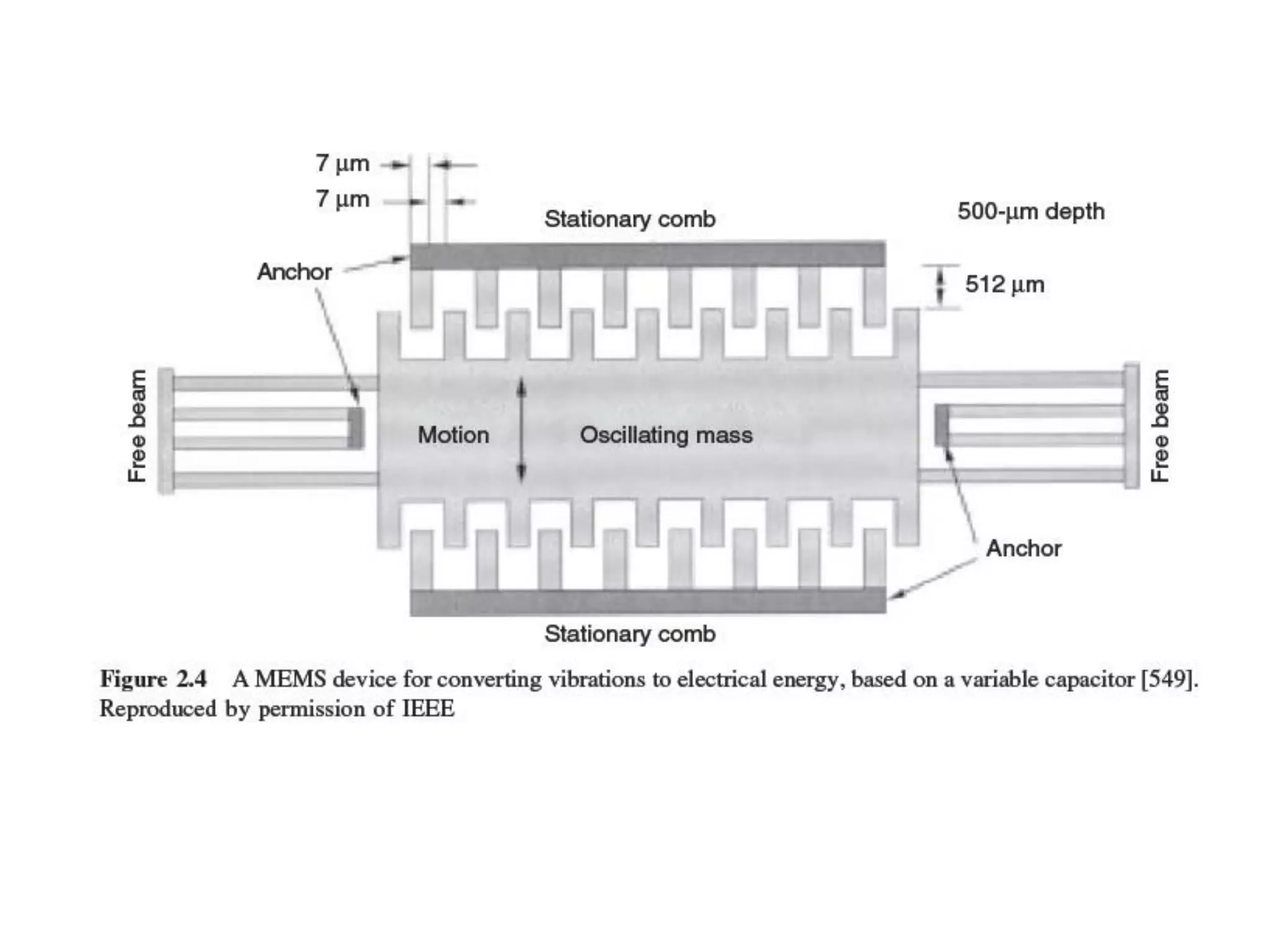
Vibrations • One almostpervasive form of mechanical energy is vibrations: • walls or windows in buildings are resonating with cars or trucks passing in the streets, machinery often has low frequency vibrations, ventilations also cause it, and so on. • The available energy depends on both amplitude and frequency of the vibration and ranges from about 0.1 μW/cm3 up to 10,000 μW/cm3 for some extreme cases (typical upper limits are lower). • Converting vibrations to electrical energy can be undertaken by various means, based on electromagnetic, electrostatic, or piezoelectric principles.
96.
Pressure variations • Somewhatsimilar to vibrations, a variation of pressure can also be used as a power source. Such piezoelectric generators are in fact used already. • One well-known example is the inclusion of a piezoelectric generator in the heel of a shoe, to generate power as a human walks about. • This device can produce, on average, 330 μW/cm2. It is, however, not clear how such technologies can be applied to WSNs.
97.
Flow of air/liquid •Another often-used power source is the flow of air or liquid in wind mills or turbines. • The challenge here is again the miniaturization, but some of the work on millimeter scale MEMS gas turbines might be reusable. • However, this has so far not produced any notable results.
• As theseexamples show, energy scavenging usually has to be combined with secondary batteries as the actual power sources are not able to provide power consistently, uninterruptedly, at a required level; rather, they tend to fluctuate over time. • This requires additional circuitry for recharging of batteries, possibly converting to higher power levels, and a battery technology that can be recharged at low currents


![Contd… • Out of band emission – The inverse to adjacent channel suppression is the out of band emission of a transmitter. – To limit disturbance of other systems, or of the WSN itself in a multichannel setup, the transmitter should produce little transmission power • Carrier sense and RSSI – The precise semantics of this carrier sense signal depends on the implementation. – For example, the IEEE 802.15.4 standard [468] distinguishes the following modes: 60](https://image.slidesharecdn.com/unitii-wsn21-210221101548/75/Sensor-Networks-Introduction-and-Architecture-60-2048.jpg)
![• The Power Amplifier (PA) accepts upconverted signals from the IF or baseband part and amplifies them for transmission over the antenna. The Low Noise Amplifier (LNA) amplifies incoming signals up to levels suitable for further processing without significantly reducing the SNR [470]. 64](https://image.slidesharecdn.com/unitii-wsn21-210221101548/75/Sensor-Networks-Introduction-and-Architecture-64-2048.jpg)