Pulse Width Modulation Signal Generation with MCUs Corrado Santoro ARSLAB - Autonomous and Robotic Systems Laboratory Dipartimento di Matematica e Informatica - Universit`a di Catania, Italy santoro@dmi.unict.it L.A.P. 1 Course Corrado Santoro Using PWM
Pulse Width Modulation 
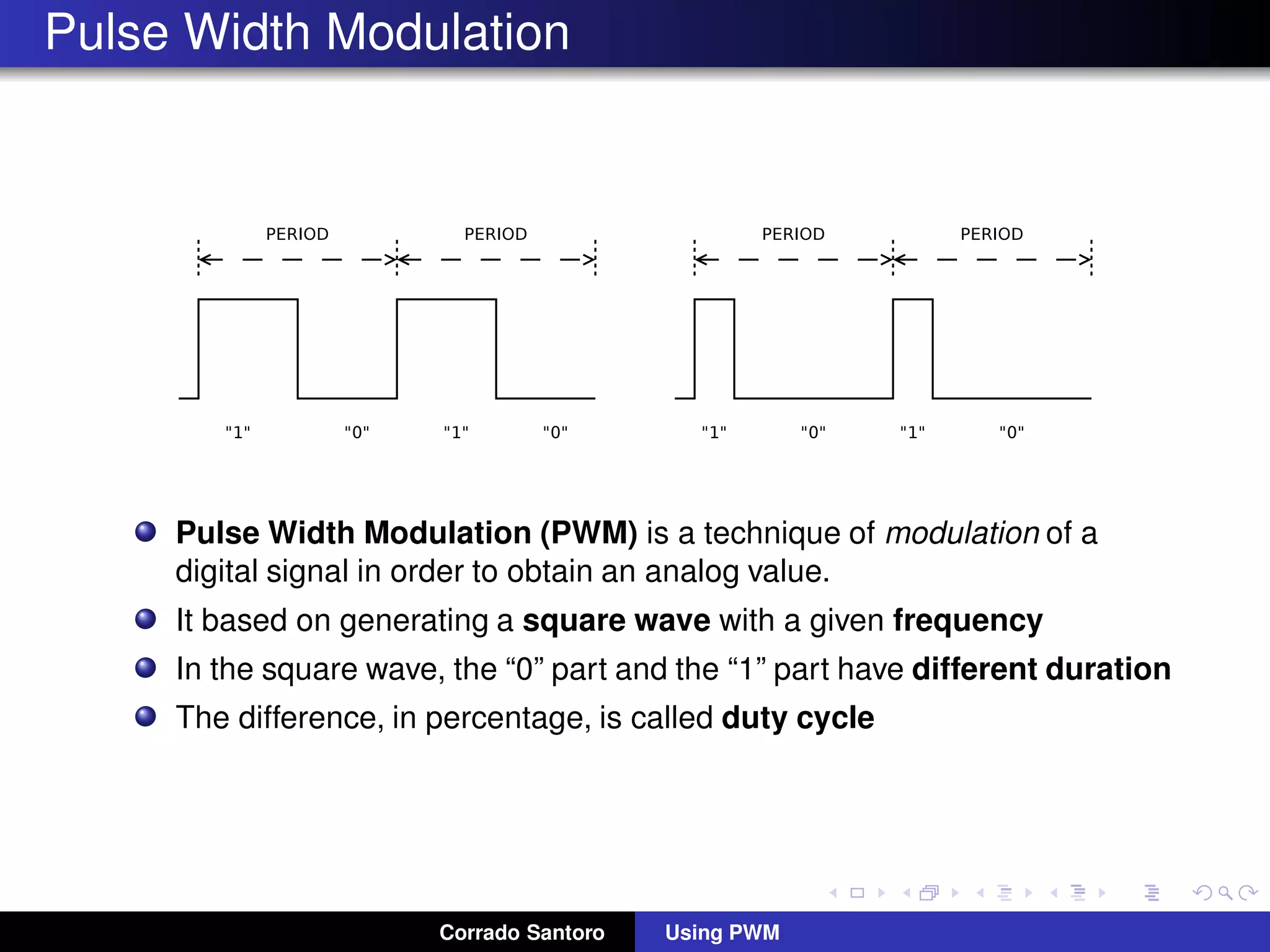
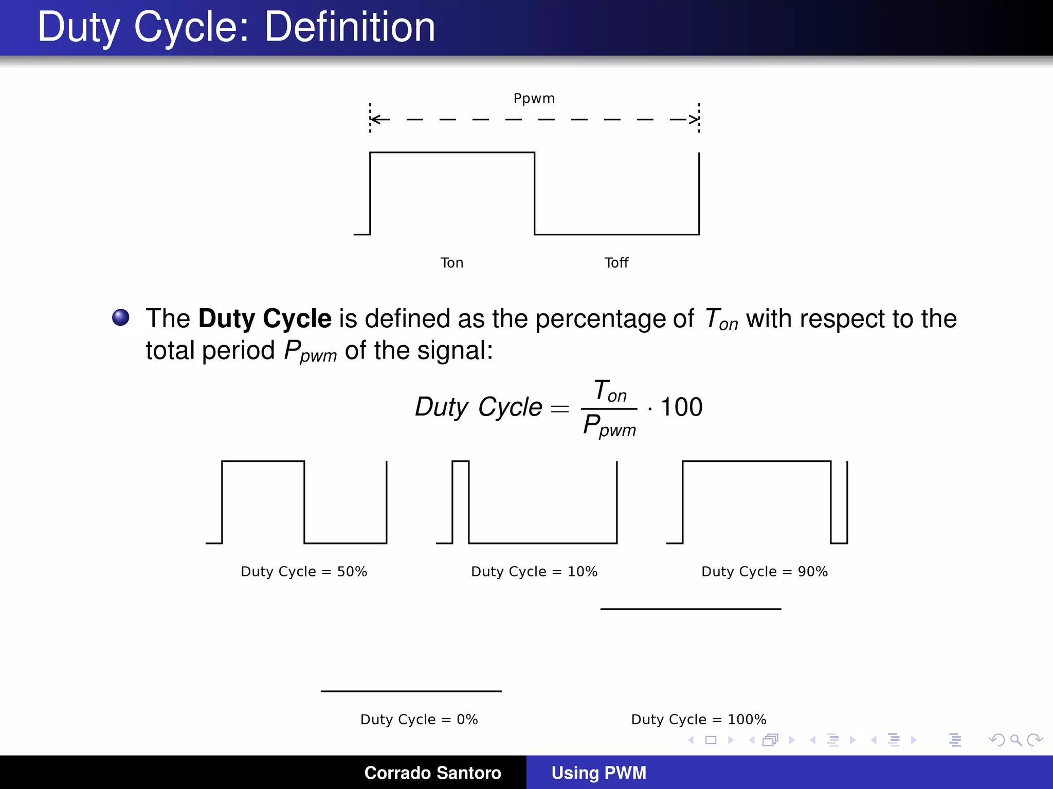
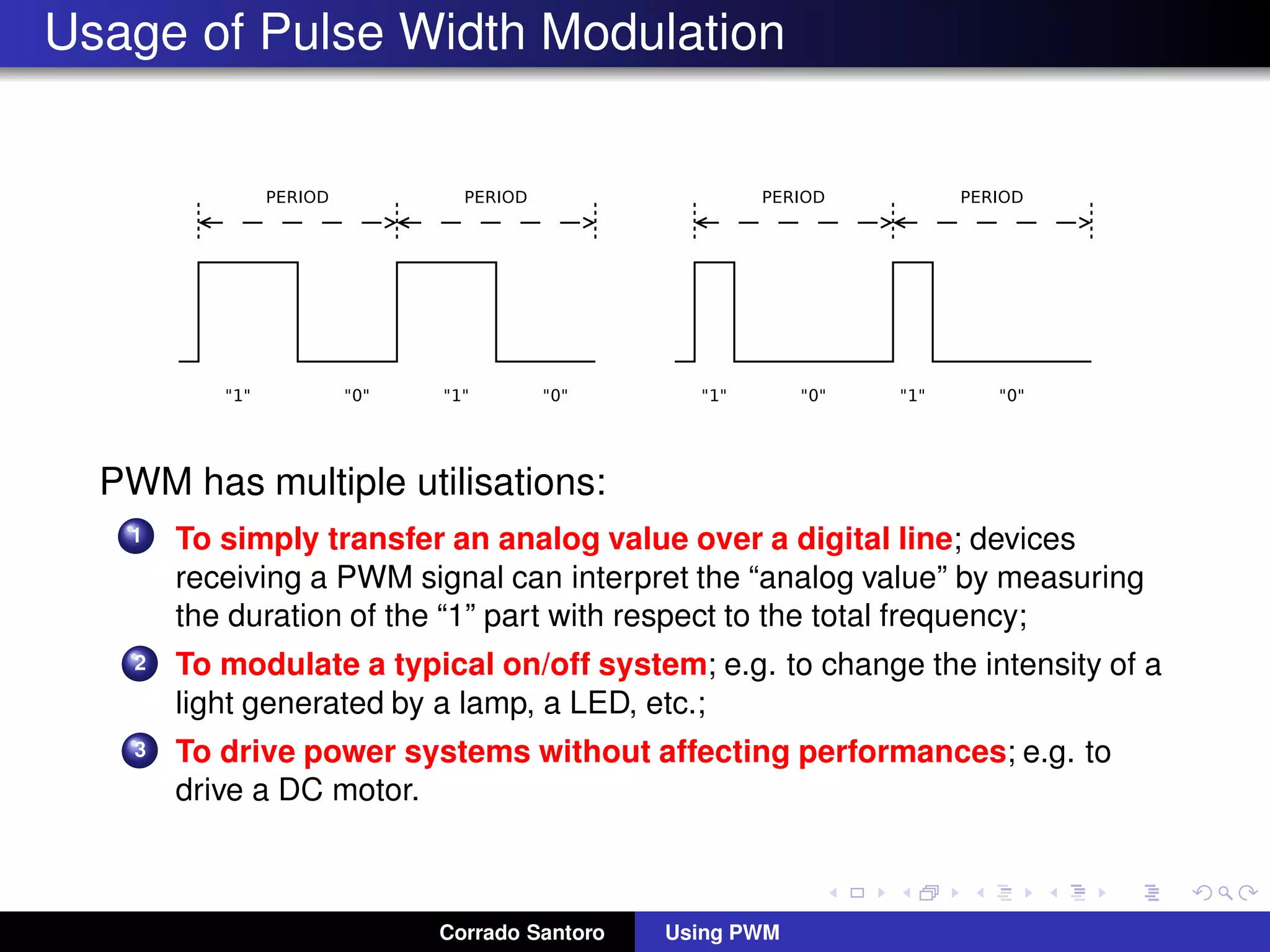
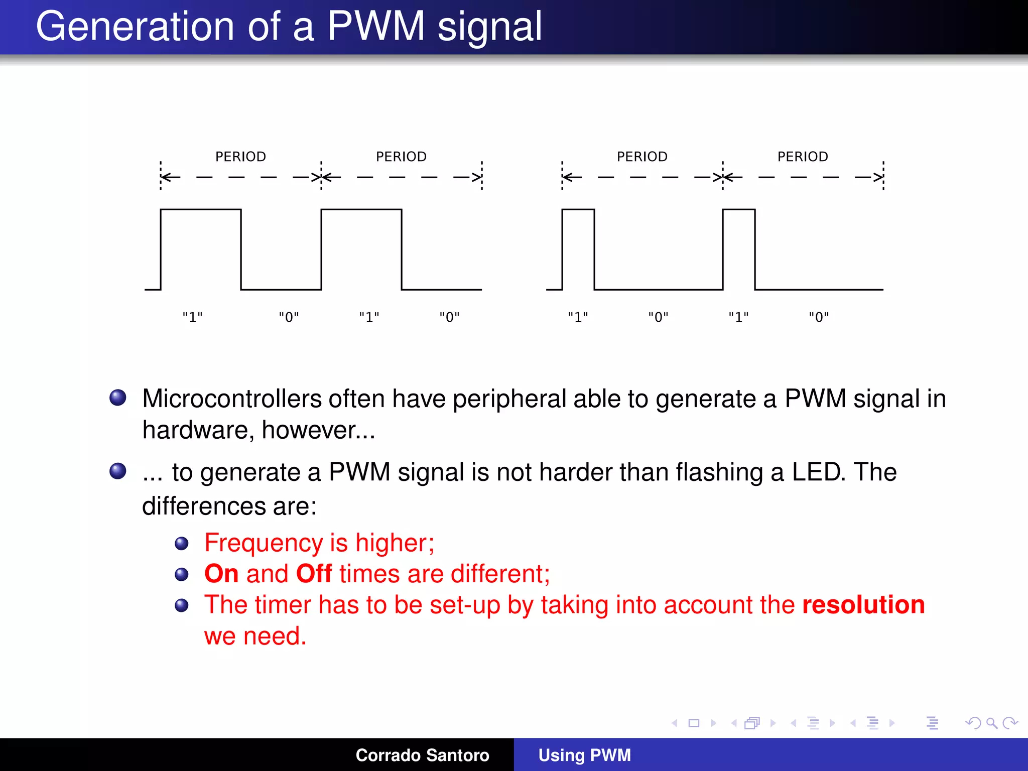
Pulse Width Modulation (PWM) is a technique of modulation of a digital signal in order to obtain an analog value. It based on generating a square wave with a given frequency In the square wave, the “0” part and the “1” part have different duration The difference, in percentage, is called duty cycle Corrado Santoro Using PWM
Duty Cycle: Definition The Duty Cycle is defined as the percentage of Ton with respect to the total period Ppwm of the signal: Duty Cycle = Ton Ppwm · 100 Corrado Santoro Using PWM
Usage of Pulse Width Modulation PWM has multiple utilisations: 1 To simply transfer an analog value over a digital line; devices receiving a PWM signal can interpret the “analog value” by measuring the duration of the “1” part with respect to the total frequency; 2 To modulate a typical on/off system; e.g. to change the intensity of a light generated by a lamp, a LED, etc.; 3 To drive power systems without affecting performances; e.g. to drive a DC motor. Corrado Santoro Using PWM
Generation of a PWM signal Microcontrollers often have peripheral able to generate a PWM signal in hardware, however... ... to generate a PWM signal is not harder than flashing a LED. The differences are: Frequency is higher; On and Off times are different; The timer has to be set-up by taking into account the resolution we need. Corrado Santoro Using PWM
Pulse Width Modulation Signal Generation with MCUs Corrado Santoro ARSLAB - Autonomous and Robotic Systems Laboratory Dipartimento di Matematica e Informatica - Universit`a di Catania, Italy santoro@dmi.unict.it L.A.P. 1 Course Corrado Santoro Using PWM

Pulse Width Modulation Signal Generation with MCUs

  • 1.
    Pulse Width ModulationSignal Generation with MCUs Corrado Santoro ARSLAB - Autonomous and Robotic Systems Laboratory Dipartimento di Matematica e Informatica - Universit`a di Catania, Italy santoro@dmi.unict.it L.A.P. 1 Course Corrado Santoro Using PWM
  • 2.
    Pulse Width Modulation PulseWidth Modulation (PWM) is a technique of modulation of a digital signal in order to obtain an analog value. It based on generating a square wave with a given frequency In the square wave, the “0” part and the “1” part have different duration The difference, in percentage, is called duty cycle Corrado Santoro Using PWM
  • 3.
    Duty Cycle: Definition TheDuty Cycle is defined as the percentage of Ton with respect to the total period Ppwm of the signal: Duty Cycle = Ton Ppwm · 100 Corrado Santoro Using PWM
  • 4.
    Usage of PulseWidth Modulation PWM has multiple utilisations: 1 To simply transfer an analog value over a digital line; devices receiving a PWM signal can interpret the “analog value” by measuring the duration of the “1” part with respect to the total frequency; 2 To modulate a typical on/off system; e.g. to change the intensity of a light generated by a lamp, a LED, etc.; 3 To drive power systems without affecting performances; e.g. to drive a DC motor. Corrado Santoro Using PWM
  • 5.
    Generation of aPWM signal Microcontrollers often have peripheral able to generate a PWM signal in hardware, however... ... to generate a PWM signal is not harder than flashing a LED. The differences are: Frequency is higher; On and Off times are different; The timer has to be set-up by taking into account the resolution we need. Corrado Santoro Using PWM
  • 6.
    Pulse Width ModulationSignal Generation with MCUs Corrado Santoro ARSLAB - Autonomous and Robotic Systems Laboratory Dipartimento di Matematica e Informatica - Universit`a di Catania, Italy santoro@dmi.unict.it L.A.P. 1 Course Corrado Santoro Using PWM