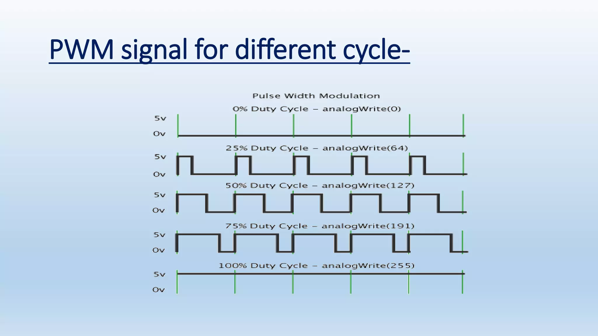
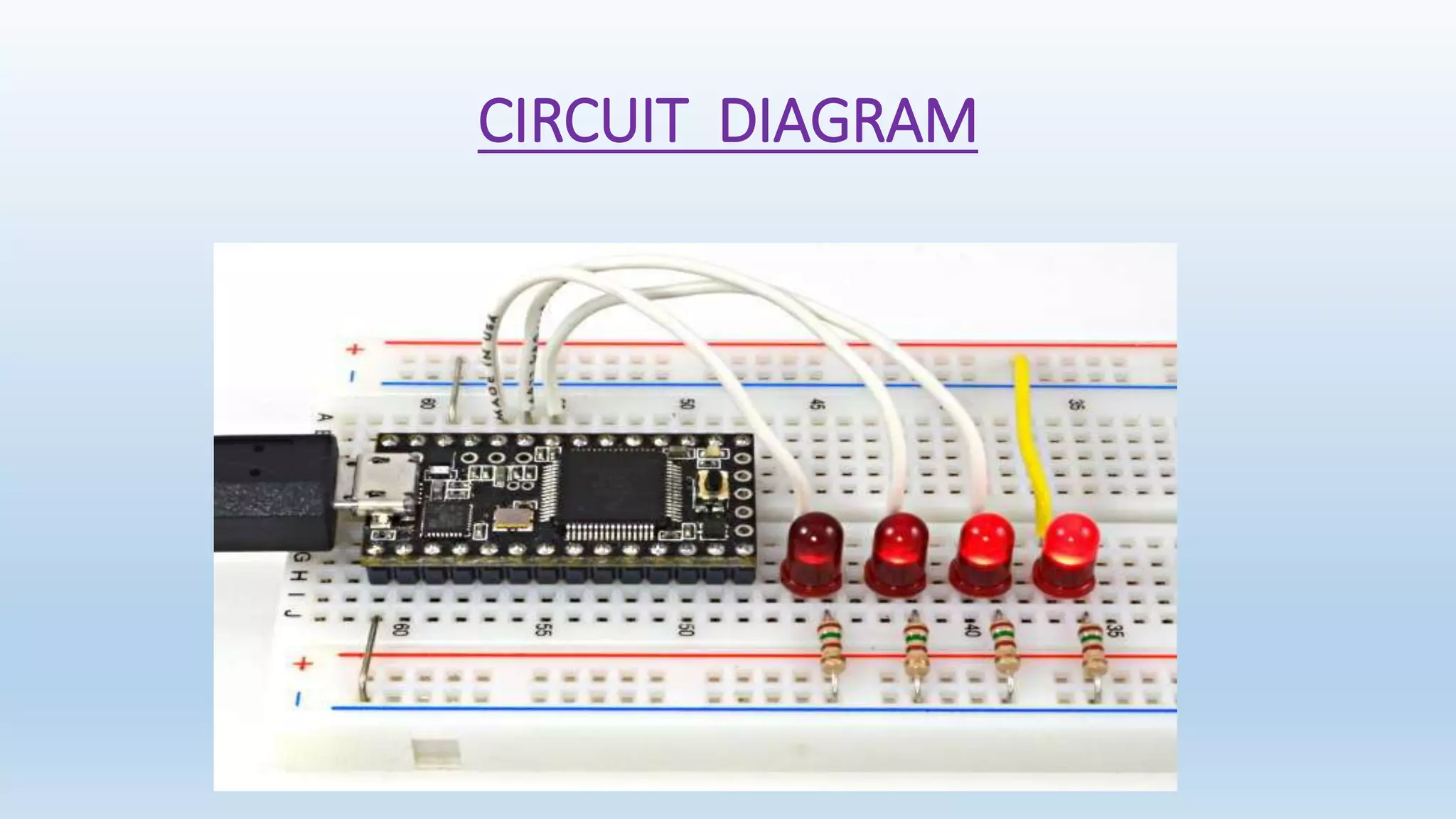
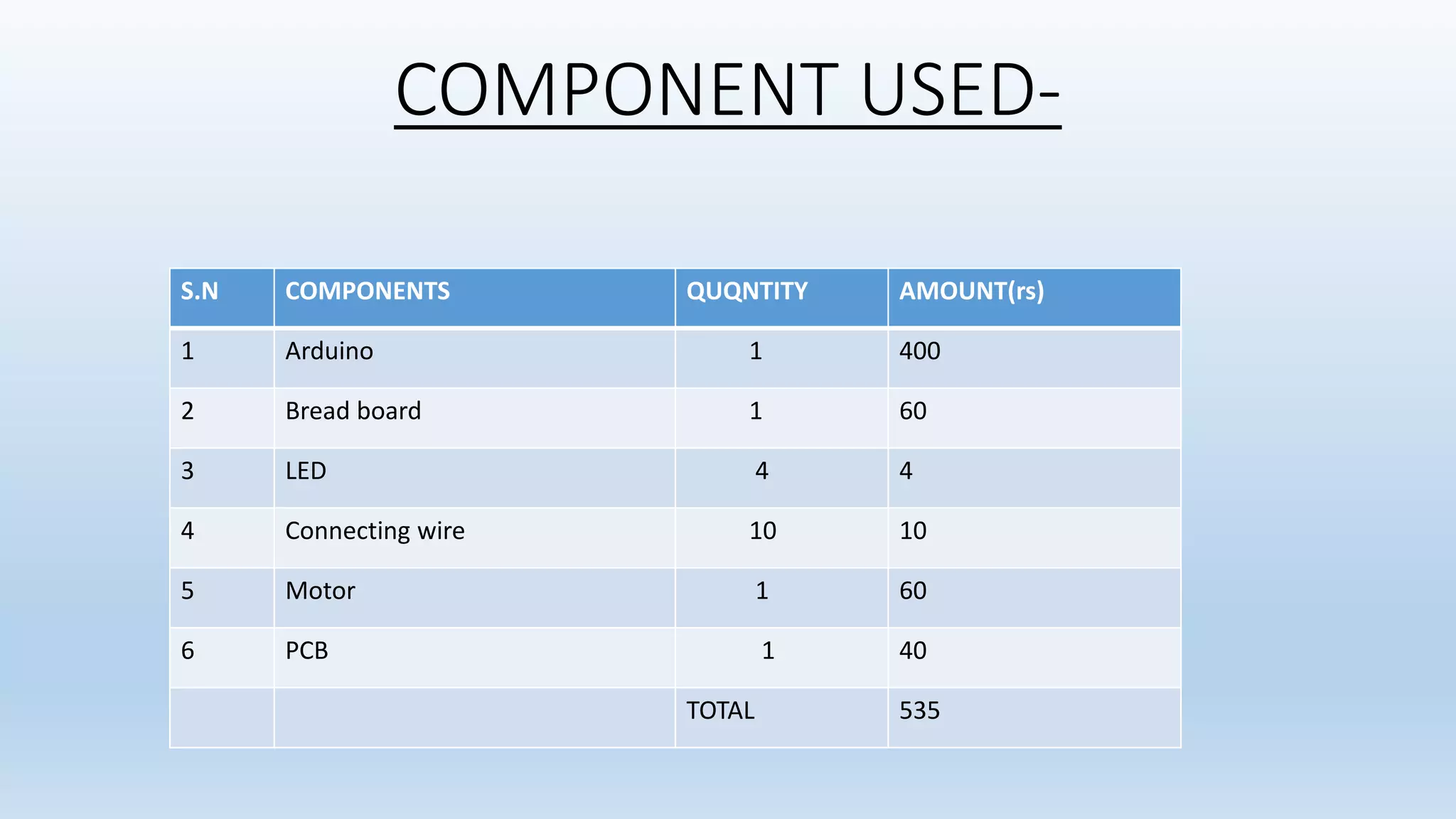
MINOR PROJECT ON GENERATE PWM SIGNAL THROUGH ARDUINO OF VARIOUS DUTY CYCLE PRESENTED BY Pankaj Prajapati(1503221045) Pawan Kumar Pal (153221047) Department of Electrical and Electronics Engineering ABES Engineering College, Ghaziabad
Pulse width modulation- • Pulse Width Modulation, or PWM, is a technique for getting analog results with digital means. • Digital control is used to create a square wave, a signal switched between on and off. This on-off pattern can simulate voltages in between full on (5 Volts) and off (0 Volts) by changing the portion of the time the signal spends on versus the time that the signal spends off. The duration of "on time" is called the pulse width. To get varying analogue values, you change, or modulate, that pulse width. • If you repeat this on-off pattern fast enough with an LED for example, the result is as if the signal is a steady voltage between 0 and 5v controlling the brightness of the LED.
PWM signal for different cycle-
WORKING • We are using LED to show the pulse width modulation . • In which we use duty cycle of 25%,50%,75%,100%. • So that LED will glow with difference intensity. • So the losses in the circuit can be reduced .
CIRCUIT DIAGRAM
COMPONENT USED- S.N COMPONENTS QUQNTITY AMOUNT(rs) 1 Arduino 1 400 2 Bread board 1 60 3 LED 4 4 4 Connecting wire 10 10 5 Motor 1 60 6 PCB 1 40 TOTAL 535
ADVANTAGE • It is simple to calculate the value needed to get a desired duty cycle. • The main advantage of PWM is that power loss in the switching devices is very low. • When a switch is off there is practically no current, and when it is on and power is being transferred to the load, there is almost no voltage drop across the switch.
APPLICATIONS • Dimming an LED. • Providing an analogue output; if the digital output is filtered, it will provide an analogue voltage between 0% and 100% . • Generating audio signals. • Providing variable speed control for motors. • Generating a modulated signal, for example to drive an infrared LED for a remote control.
REFERENCES • Wikipedia.com • Google.com • Arduino.cc

Generate pwm signal through arduino of various duty

  • 1.
    MINOR PROJECT ON GENERATE PWMSIGNAL THROUGH ARDUINO OF VARIOUS DUTY CYCLE PRESENTED BY Pankaj Prajapati(1503221045) Pawan Kumar Pal (153221047) Department of Electrical and Electronics Engineering ABES Engineering College, Ghaziabad
  • 2.
    Pulse width modulation- •Pulse Width Modulation, or PWM, is a technique for getting analog results with digital means. • Digital control is used to create a square wave, a signal switched between on and off. This on-off pattern can simulate voltages in between full on (5 Volts) and off (0 Volts) by changing the portion of the time the signal spends on versus the time that the signal spends off. The duration of "on time" is called the pulse width. To get varying analogue values, you change, or modulate, that pulse width. • If you repeat this on-off pattern fast enough with an LED for example, the result is as if the signal is a steady voltage between 0 and 5v controlling the brightness of the LED.
  • 3.
    PWM signal fordifferent cycle-
  • 4.
    WORKING • We areusing LED to show the pulse width modulation . • In which we use duty cycle of 25%,50%,75%,100%. • So that LED will glow with difference intensity. • So the losses in the circuit can be reduced .
  • 5.
  • 6.
    COMPONENT USED- S.N COMPONENTSQUQNTITY AMOUNT(rs) 1 Arduino 1 400 2 Bread board 1 60 3 LED 4 4 4 Connecting wire 10 10 5 Motor 1 60 6 PCB 1 40 TOTAL 535
  • 7.
    ADVANTAGE • It issimple to calculate the value needed to get a desired duty cycle. • The main advantage of PWM is that power loss in the switching devices is very low. • When a switch is off there is practically no current, and when it is on and power is being transferred to the load, there is almost no voltage drop across the switch.
  • 8.
    APPLICATIONS • Dimming anLED. • Providing an analogue output; if the digital output is filtered, it will provide an analogue voltage between 0% and 100% . • Generating audio signals. • Providing variable speed control for motors. • Generating a modulated signal, for example to drive an infrared LED for a remote control.
  • 9.