Programming PIC Microcontrollers Module: EE2A2 Embedded Microprocessor Systems Programming PIC Microcontrollers Module: EE2A2 Embedded Microprocessor Systems Lecturer: James Grimblebyy URL: http://www.personal.rdg.ac.uk/~stsgrimb/ email: j.b.grimbleby reading.ac.ukj g y g Number of Lectures: 5 Recommended text book: R Barnett L O’Cull and S FoxR. Barnett, L O Cull and S. Fox Embedded C Programming and the Microchip PIC Thomson (2004)Thomson (2004) ISBN 1401837484 School of Systems Engineering - Electronic Engineering Slide 1James Grimbleby
Programming PIC MicrocontrollersProgramming PIC Microcontrollers Recommended Text Book:Recommended Text Book: R. Barnett, L O’Cull and S. FoxR. Barnett, L O Cull and S. Fox Embedded C Programming and the Microchip PICp Thomson (2004) ISBN 1401837484 Price (Amazon) £47 School of Systems Engineering - Electronic Engineering Slide 2James Grimbleby
Programming PIC Microcontrollers On-line book describing PIC microcontrollers: Programming PIC Microcontrollers On-line book describing PIC microcontrollers: htt // ik l kt ik / li h/ d t/b k /http://www.mikroelektronika.co.yu/english/product/books/ PICbook/0_Uvod.htm School of Systems Engineering - Electronic Engineering Slide 3James Grimbleby
Programming PIC MicrocontrollersProgramming PIC Microcontrollers Manual for CCS PICManual for CCS PIC C compiler: http://www ccsinfo com/downloads/ccs c manual pdf School of Systems Engineering - Electronic Engineering Slide 4James Grimbleby http://www.ccsinfo.com/downloads/ccs_c_manual.pdf
Programming PIC MicrocontrollersProgramming PIC Microcontrollers This course is about programming PIC microcontrollers in C using the CCS PIC-C compiler Topics covered include: PIC architecture PIC specific limitations and extensions to CPIC-specific limitations and extensions to C Programming PIC hardware such as ports, ADC, timers, etc Using software librariesUsing software libraries You should already be familiar with the C and C++You should already be familiar with the C and C++ programming languages School of Systems Engineering - Electronic Engineering Slide 5James Grimbleby
Assessment This nit ill be assessed b a m ltiple choice test Assessment This unit will be assessed by a multiple-choice test The multiple choice test will last for 30 minutes during whichThe multiple-choice test will last for 30 minutes, during which 20 questions must be answered You will be permitted to bring your notebooks and the course notes into the testnotes into the test The test will be held at the end of the Autumn termThe test will be held at the end of the Autumn term The marks from this test will contribute to the overall mark forThe marks from this test will contribute to the overall mark for the module EE2A2 School of Systems Engineering - Electronic Engineering Slide 6James Grimbleby
Multi-Choice Test Example This question relates to the use of the CCS PIC C Multi Choice Test Example This question relates to the use of the CCS PIC C compiler. A variable q is declared:A variable q is declared: long int q; k l i hq can take on any value in the range: (a) -128 to +127 (b) 0 2(b) 0 to 255 (c) -32768 to +32767 (d) 0 to 65535(d) 0 to 65535 (e) -2147483648 to + 2147483647 Answer: School of Systems Engineering - Electronic Engineering Slide 7James Grimbleby
Programming PIC MicrocontrollersProgramming PIC Microcontrollers Lecture 1 PIC ArchitecturePIC Architecture School of Systems Engineering - Electronic Engineering Slide 8James Grimbleby
PIC Microcontroller Architecture PICs use Harvard architecture and a RISC instruction set PIC Microcontroller Architecture PICs use Harvard architecture and a RISC instruction set von Neuman Architecture: P d von Neuman Architecture: CPU Program and data memory Harvard Architecture: CPU DataProgram CPU memorymemory School of Systems Engineering - Electronic Engineering Slide 9James Grimbleby
PIC Microcontroller ArchitecturePIC Microcontroller Architecture Flash Program Counter/ tiprogram memory RAM file registers counter timers g Instruction register Address MUX Stack FSR Status register I/O ports Brn out reset g Instruction MUX Start up timer Watchdog ALU decode Peripherals W register Timing generation Low volt prog Debugger School of Systems Engineering - Electronic Engineering Slide 10James Grimbleby
PIC Microcontroller Peripherals The 18F452 PIC has the following peripherals: PIC Microcontroller Peripherals The 18F452 PIC has the following peripherals: Data ports A (6-bit) B (8-bit) C (8-bit) D (8-bit) E (3-bit)Data ports A (6 bit), B (8 bit), C (8 bit), D (8 bit), E (3 bit) Timer/counter modules 0 (8-bit), 1 (16-bit), 2 (8-bit), 3 (16-bit) CCP/PWM modules (2) I2C/SPI i l tI2C/SPI serial port USART (RS-232, RS-485)( , ) Analogue-to-digital converter (10-bit) with 10 way input multiplexermultiplexer EEPROM (256 byte) School of Systems Engineering - Electronic Engineering Slide 11James Grimbleby
Clock Generator PICs use a fully static design so that any clock frequency up Clock Generator PICs use a fully static design so that any clock frequency up to the specified maximum can be used There are 4 possible clock configurations: external clock (eg crystal oscillator module)- external clock (eg crystal oscillator module) - self-oscillating with external crystal or ceramic resonator - external or self-oscillating with phase-locked loop - self-oscillating with external RC In practice the choice will normally be a compromise between cost and clock speed or clock stability School of Systems Engineering - Electronic Engineering Slide 12James Grimbleby
Reset A reset puts the PIC in a well-defined initial state so that the Reset p processor starts executing code from the first instruction Resets can result from: - external reset by MCLR pulled low- external reset by MCLR pulled low - reset on power-up - reset by watchdog timer overflow t l b t- reset on power supply brown-out Reset can be sed as a last resort for reco ering from someReset can be used as a last resort for recovering from some catastrophic software event but all current data will be lost School of Systems Engineering - Electronic Engineering Slide 13James Grimbleby
Central Processing UnitCentral Processing Unit The CPU fetches instructions from memory, decodes them, and passes them to the ALU for execution The arithmetic logic unit (ALU) is responsible for adding, subtracting, shifting and performing logical operations Th ALU i j i i hThe ALU operates in conjunction with: - a general-purpose register called the W register - an f register that can be any location in data memory lit l b dd d i th i t ti d- literals embedded in the instruction code School of Systems Engineering - Electronic Engineering Slide 14James Grimbleby
Memory Organisation - Stack A 31-level stack stores the return address during interrupts Memory Organisation Stack A 31 level stack stores the return address during interrupts and subroutine calls Program Counter 21 bit Stack level 1 Stack level 2 ....... Stack level 31 School of Systems Engineering - Electronic Engineering Slide 15James Grimbleby
Memory Organisation - ProgramMemory Organisation Program Reset vector 0x0000 Program memory High priority int vector 0x0008 Program memory contains the Reset and Interrupt vectors Low priority int vector 0x0018 Interrupt vectors The PIC18F452 has 32k P The PIC18F452 has 32k (0x8000) locations of program memory Program memory program memory 0x7FFF School of Systems Engineering - Electronic Engineering Slide 16James Grimbleby
Memory Organisation - Data 0x000 Memory Organisation Data Data memory contains general GPR bank 0 0x000 0x100 GPR bank 1 0x200Data memory contains general purpose registers (GPRs) and special function registers GPR bank 2 GPR bank 3 0x200 0x300 special function registers (SFRs) GPR bank 3 GPR bank 4 GPR bank 5 0x400 0x500 The PIC18F452 has 1536 (0x600) locations of GPR data GPR bank 5 0x600 (0x600) locations of GPR data memory Unused 0xFFF 0xF80 SFRs School of Systems Engineering - Electronic Engineering Slide 17James Grimbleby
Memory Organisation – SFRs Port A 0 F80 SPBRG 0 FAF Memory Organisation SFRs The memory block Port A 0xF80 0xF81Port B SPBRG 0xFAF ..... 0xF80 to 0xFFF (128 locations) references Port C Port D 0xF82 0xF83 Timer1L 0xFCE 0xFCFTimer1H special function registers (SFRs) Port E .... 0xF84 Timer0L ..... 0xFD6 Some of the SFRs h h .. 0xF93 0xF92Tris A Tris B Timer0L 0xFD6 0xFD7Timer0H .. are shown here 0xF93Tris B Tris C 0xF94 Wreg 0xFE8 ... . Tris D Tris E 0xF95 0xF96 StkPtr 0xFFC ..... School of Systems Engineering - Electronic Engineering Slide 18James Grimbleby
PIC Instruction Set The PIC instruction set has a small number of simple (RISC) PIC Instruction Set The PIC instruction set has a small number of simple (RISC) instructions PIC16 series: 35 instructions coded into 14 bits PIC 18 series: 59 instructions coded into 16 bitsPIC 18 series: 59 instructions coded into 16 bits PIC 24 series: 71 instructions coded into 24 bits Most instructions are executed in one instruction cycle which corresponds to 4 clock cycles Thus a PIC operating at 40 MHz clock frequency will have an instruction rate of 10 MIPS. School of Systems Engineering - Electronic Engineering Slide 19James Grimbleby
PIC 18Fxxx Instruction Set Most PIC 18Fxxx instructions occupy a single 16-bit program PIC 18Fxxx Instruction Set memory location Each instruction consists of an opcode and one or moreEach instruction consists of an opcode and one or more operands The instruction set is highly orthogonal and can be partitioned:partitioned: - 31 byte-oriented file register operations - 5 bit-oriented file register operations - 23 control instructions - 10 literal instructions - 8 data memory – program memory operations School of Systems Engineering - Electronic Engineering Slide 20James Grimbleby 8 data memory program memory operations
PIC 18Fxxx Instruction SetPIC 18Fxxx Instruction Set Byte-oriented file register operations : ADDWF Add W d f lt i W fADDWF Add W and f: result in W or f CLRF Clear f DECF Decrement fDECF Decrement f MOVF Move contents of f to f or W Bit-oriented file register operations: BCF Clear bit in f BTFSC Test bit in f; skip if clear School of Systems Engineering - Electronic Engineering Slide 21James Grimbleby
PIC 18Fxxx Instruction Set Control instructions : PIC 18Fxxx Instruction Set BRA Branch unconditionally CALL Call subroutine (function)CALL Call subroutine (function) RETURN Return from subroutine (function) BNZ Branch if not zeroBNZ Branch if not zero Literal instructions :Literal instructions : MOVLW Move literal to W ADDLW Add lit l t WADDLW Add literal to W Data memor program memor operationsData memory – program memory operations: TBLRD*+ Table read with post-increment School of Systems Engineering - Electronic Engineering Slide 22James Grimbleby p
Status Register The 8-bit status register is set during arithmetic operations Status Register - - - N OV Z DC C g g p N Negative bit - result of arithmetic operation was negative OV Overflow bit – overflow occurred for signed arithmeticOV Overflow bit – overflow occurred for signed arithmetic Z Zero bit - result of arithmetic operation was zero DC Digit Carry bit – carry out from 4th low order bit of resultDC Digit Carry bit carry out from 4 low order bit of result C Carry bit – carry out from most-significant bit of result The bits of the status register can then be used in conditional branches, for example:, p BNZ Branch if Not Zero BOV Branch of OVerflow School of Systems Engineering - Electronic Engineering Slide 23James Grimbleby
Programming PIC MicrocontrollersProgramming PIC Microcontrollers Lecture 2 CCS CompilerCCS Compiler School of Systems Engineering - Electronic Engineering Slide 24James Grimbleby
What is C ? In 1970 a team at Bell Labs led by Brian Kernighan were What is C ? y g developing the UNIX computer operating system They required a high-level computer language for writing computer operating systems Starting from an existing language called BCPL they Cdeveloped C C d t it th t i f UNIX tC was used to write the next version of UNIX system software UNIX eventually became the world's first portable operating system School of Systems Engineering - Electronic Engineering Slide 25James Grimbleby system
What is C ? C has now become a widely used professional language for What is C ? y p g g various reasons: It h hi h l l t tIt has high level constructs It can handle low level activities It produces efficient programs It can be compiled on a wide variety of computersIt can be compiled on a wide variety of computers The standard for C programs was originally the features setThe standard for C programs was originally the features set by Brian Kernighan Later an international standard was developed: ANSI C (American National Standards Institute) School of Systems Engineering - Electronic Engineering Slide 26James Grimbleby (American National Standards Institute)
What is C++ ? More recently another group at AT&T led by Bjarne Stroustrup What is C ? More recently another group at AT&T led by Bjarne Stroustrup developed C to reflect modern programming techniques The new language was called C++ C++ has stronger type checking and supports object-oriented programming C++ may be considered in several ways.: An extension of C A "data abstraction" improvement on CA data abstraction improvement on C A base for "object oriented" programming School of Systems Engineering - Electronic Engineering Slide 27James Grimbleby
Why Program PICs in C? C is a portable language, requiring minimal modification when Why Program PICs in C? p g g q g transferring programs from one processor to another Programming in a high-level language rather than assembler allows programs to be developed much more rapidly Typically a program which takes a few weeks in assembler C fcan be written in C in a few days Code efficiency of compiled C programs is typically 80% ofCode efficiency of compiled C programs is typically 80% of well-written assembler programs The related language C++ is too complex for use with the present generation of PICs School of Systems Engineering - Electronic Engineering Slide 28James Grimbleby p g
CCS PIC Compiler A compiler converts a high-level language program to machine CCS PIC Compiler instructions for the target processor A il i il th tA cross-compiler is a compiler that runs on a processor (usually a PC) that is different from the target processor Most embedded systems are now programmed using the C/C++ languageC/C++ language Several C compilers are available that target Microchip PICs,Several C compilers are available that target Microchip PICs, for example HiTech, Microchip and CCS The PIC programming laboratory at Reading is equipped with the CCS cross-compiler School of Systems Engineering - Electronic Engineering Slide 29James Grimbleby
CCS PIC Compiler int main() { CCS PIC Compiler PIC { int x, y, z; for (;;) { lcd(clear); USB PC with CCS compiler ICD2 PIC system P dit d d il d t PIC hi i t ti CCS compiler debugger Programs are edited and compiled to PIC machine instructions on a PC PIC machine instructions are uploaded from PC to PIC system via the ICD2 debuggergg Code is executed on the PIC system and can be debugged (break points inspect variables single step etc ) using PC School of Systems Engineering - Electronic Engineering Slide 30James Grimbleby (break points, inspect variables, single step etc.) using PC
CCS PIC CompilerCCS PIC Compiler School of Systems Engineering - Electronic Engineering Slide 31James Grimbleby
CCS PIC Compiler The CCS compiler comes with an integral syntax-aware editor CCS PIC Compiler CCS C is standard C plus limited support for reference t i f tiparameters in functions PIC specific pre processor directives are provided in additionPIC-specific pre-processor directives are provided in addition to the standard directives (#include, #define etc): #inline implement the following function inline #priority set priority of interrupts Additional functions supporting PIC hardware are provided: output_low() set an I/O port bit low delay_us() delay by a specified number of µs School of Systems Engineering - Electronic Engineering Slide 32James Grimbleby y y p µ
CCS PIC Compiler Data Types PICs are optimised for processing single bits or 8-bit words, CCS PIC Compiler Data Types p p g g and this is reflected the CCS compiler word sizes: short int (or int1) 1 bit int (or int8) 8 bit 0 or 1 0 to 255int (or int8) 8 bit long int (or int16) 16 bit i t32 32 bit 0 to 255 0 to 65535 0 t 4294967295int32 32 bit char 8 bit 0 to 4294967295 0 to 255 38 38float 32 bit ±3×10-38 to ±3×10+38 Contrary to the C standard, CCS C integers are by default unsigned School of Systems Engineering - Electronic Engineering Slide 33James Grimbleby
CCS PIC Compiler Data Types In CCS C it is necessary to use the signed qualifier if signed CCS PIC Compiler Data Types y g q g integer are required: short int 1 bit signed int 8 bit 0 or 1 -128 to +127signed int 8 bit signed long int 16 bit i d i t32 32 bit -128 to +127 -32768 to +32767 2147M t 2147Msigned int32 32 bit char 8 bit -2147M to +2147M 0 to 255 38 38float 32 bit ±3×10-38 to ±3×10+38 It is not appropriate to use the signed qualifier with char or short int, and floats are signed by default School of Systems Engineering - Electronic Engineering Slide 34James Grimbleby
Constants Constants can be specified in either decimal, octal, Constants 123 Decimal 'n' Line Feed hexadecimal or binary, or as a special character: 123 Decimal 0123 Octal 0x123 Hex n Line Feed 'r' Return Feed 't' TAB0x123 Hex 0b010010 Binary t TAB 'b' Backspace 'f' Form Feed 'x' Character '010' Octal character f Form Feed 'a' Bell 'v' Vertical Space010 Octal character '0xA5’ Hex character v Vertical Space '?' Question Mark ''' Single Quote S g e Quote '"' Double Quote '' A Single Backslash School of Systems Engineering - Electronic Engineering Slide 35James Grimbleby g
CCS PIC Compiler Data Types In CCS C a short int is effectively a boolean variable CCS PIC Compiler Data Types y To make programs more readable it is a helpful to make use of the definitions (already in the device definition files): #define boolean short int#define boolean short int #define false 0 #define true 1 Now it is possible to declare boolean variables: boolean finished = true; (|| && )The standard boolean operators (||, &&, ! etc) can be used with these variables School of Systems Engineering - Electronic Engineering Slide 36James Grimbleby
Multi-Precision Operations It is often necessary to process data words that are larger Multi Precision Operations It is often necessary to process data words that are larger than can be operated on by a single instruction PIC instructions only operate on 8-bit words Multi-precision arithmetic uses a sequence of basic instructions on existing data types In CCS C the long int (16 bit) and int32 (32 bit) types are processed using multi-precision arithmetic This is much more expensive in time and code size than single instructions School of Systems Engineering - Electronic Engineering Slide 37James Grimbleby
Multi-Precision OperationsMulti Precision Operations Ams Als += Bms Bls Als += Bls Overflow? Ams ++ Yes No Ams += Bms School of Systems Engineering - Electronic Engineering Slide 38James Grimbleby
Multi-Precision OperationsMulti Precision Operations 16-bit addition using 8-bit operations: Ams Als += Bms Bls MOVF Bls, W ADDWF Als MOVF Bms WMOVF Bms, W ADDWFC Ams School of Systems Engineering - Electronic Engineering Slide 39James Grimbleby
Multi-Precision OperationsMulti Precision Operations 32-bit addition using 8-bit operations: Ams +=A2 A1 Als Bms B2 B1 Bls MOVF Bls, W ADDWF AlsADDWF Als MOVF B1, W ADDWFC A1 MOVF B2, W ADDWFC A2 MOVF Bms WMOVF Bms, W ADDWFC Ams School of Systems Engineering - Electronic Engineering Slide 40James Grimbleby
Reference Parameters CCS C provides C++ like reference parameters to functions: Reference Parameters CCS C provides C like reference parameters to functions: Traditional C: CCS C (C++): void swap(int &x, int &y)void swap(int *x, int *y) ( ) void swap(int &x, int &y) { int temp = x; void swap(int x, int y) { int temp = *x; * * x = y; y = temp; } *x = *y; *y = temp; } } int j = 5, k = 8; (j k) } int j = 5, k = 8; (&j &k) swap(j, k);swap(&j, &k); School of Systems Engineering - Electronic Engineering Slide 41James Grimbleby
Built-In Functions RS-232 I/O: SPI two wire I/O: Discrete I/O: Built In Functions getc() putc() fgetc() read_bank() setup_spi() spi read() output_low() output_high() output float()fgetc() gets() puts() f t () spi_read() spi_write() spi_data_is_in() output_float() output_bit() input() t t ()fgets() fputc() fputs() output_X() output_toggle() input_state() printf() kbhit() fprintf() input_X() port_b_pullups() set_tris_X()p () set_uart_speed() perror() assert() _ _ () assert() getchar() putchar() setup uart() School of Systems Engineering - Electronic Engineering Slide 42James Grimbleby setup_uart()
Built-In Functions Parallel Slave I/O: I2C I/O Processor control: Built In Functions Parallel Slave I/O: setup_psp() psp_input_full() I C I/O i2c_start() i2c_stop() Processor control: sleep() reset_cpu() psp_output_full() psp_overflow() i2C_read i2c_write() i2c poll() restart_cause() disable_interrupts() enable interrupts()i2c_poll() enable_interrupts() ext_int_edge() read_bank() write bank()write_bank() label_address() goto_address() t ()getenv() clear_interrupts setup_oscillator() School of Systems Engineering - Electronic Engineering Slide 43James Grimbleby
Built-In Functions Bit/Byte Manipulation: Standard C Math: Built In Functions shift_right() shift_left() rotate right() abs() acos() asin() fabs() fmod() atan2()rotate_right() rotate_left() bit_clear() bit t() asin() atan() ceil() () atan2() frexp() ldexp() df()bit_set() bit_test() swap() cos() exp() floor() modf() sqrt() tan() make8() make16() make32() labs() sinh() log() div() ldiv() () g() log10() pow() sin()sin() cosh() tanh() School of Systems Engineering - Electronic Engineering Slide 44James Grimbleby
Built-In Functions Standard C Char: Built In Functions atoi() atoi32() atol() strcmp() stricmp() strncmp() strtol() strtoul() strncat()atol() atof() tolower() toupper() strncmp() strcat() strstr() strchr() strncat() strcoll() strxfrm() toupper() isalnum() isalpha() i () strchr() strrchr() isgraph() i t l()isamoung() isdigit() islower() iscntrl() strtok() strspn() isspace() isupper() isxdigit() strcspn() strpbrk() strlwr()g () strlen() strcpy() strncpy() () sprintf() isprint() strtod() School of Systems Engineering - Electronic Engineering Slide 45James Grimbleby strncpy() strtod()
Built-In FunctionsBuilt In Functions A/D Conversion: setup_vref() d () Timers: setup_timer_X() i () Standard C memory: memset() ()setup_adc_ports() setup_adc() set_adc_channel() set_timer_X() get_timer_X() setup_counters() memcpy() offsetof() offsetofbit() read_adc() p setup_wdt() restart_wdt() malloc() calloc() free()free() realloc() memmove() memcmp() Analog Compare: setup_comparator() memcmp() memchr() School of Systems Engineering - Electronic Engineering Slide 46James Grimbleby
Built-In Functions Capture/Compare/PWM: Internal EEPROM: Built In Functions Capture/Compare/PWM: setup_ccpX() set pwmX duty() Internal EEPROM: read_eeprom() write eeprom()set_pwmX_duty() setup_power_pwm() setup_power_pwm_pins() set power pwmx duty() write_eeprom() read_program_eeprom() write_program_eeprom() read calibration()set_power_pwmx_duty() set_power_pwm_override() read_calibration() write_program_memory() read_program_memory() i l ()write_external_memory() erase_program_memory() setup_external_memory()Delays: Standard C Special: delay_us() delay_ms() delay cycles() rand() srand() delay_cycles() School of Systems Engineering - Electronic Engineering Slide 47James Grimbleby
Device Definition File A CCS C program will start with a number of pre-processor Device Definition File A CCS C program will start with a number of pre-processor directives similar to: #include <18F452.H> #fuses HS,NOWDT,NOBROWNOUT,NOPROTECT,PUT # d l ( l k 20000000)#use delay(clock=20000000) #include "lcd.c" The first directive instructs the compiler to include the system header file 18F452.H This is a device-specific file that contains information about the location of SFRs and the values to be written to them School of Systems Engineering - Electronic Engineering Slide 48James Grimbleby
Device Definition File PIC 18F452 Definition File (18F452.H): Device Definition File PIC 18F452 Definition File (18F452.H): #define PIN_A0 31744 #define PIN A1 31745#define PIN_A1 31745 . . . . . . . . #define PIN_B0 31752 #define PIN B1 31753#define PIN_B1 31753 . . . . . . . . #define T1_DISABLED 0 #define T1 INTERNAL 0x85#define T1_INTERNAL 0x85 #define T1_EXTERNAL 0x87 #define T1_EXTERNAL_SYNC 0x83 . . . . . . . . #define CCP_OFF 0 #define CCP_CAPTURE_FE 4 #define CCP_CAPTURE_RE 5 #define CCP_CAPTURE_DIV_4 6 . . . . . . . . School of Systems Engineering - Electronic Engineering Slide 49James Grimbleby
Fuses CCS C provides a fuse directive: Fuses p #fuses HS,NOWDT,NOBROWNOUT,NOPROTECT,PUT which specifies the states of the configuration fuses that should be programmed onto the PICshould be programmed onto the PIC In this example:In this example: HS Clock is a high-speed crystal or resonator NOWDT W t hd ti i di bl dNOWDT Watchdog timer is disabled NOBROWNOUT Brown-out detector is disabled NOPROTECT Code protect offNOPROTECT Code protect off PUT Power-on timer is enabled School of Systems Engineering - Electronic Engineering Slide 50James Grimbleby
Delays CCS C provides functions for generating delays: Delays p g g y delay_us() delay ms()delay_ms() These delay functions actually delay by a number of machiney y y y cycles The compiler needs to know the clock frequency in order to calculate the required number of machine cycles #use delay(clock=20000000) This use-delay directive specifies that the clock frequency of the PIC is 20 MHz School of Systems Engineering - Electronic Engineering Slide 51James Grimbleby the PIC is 20 MHz
Multiple Source Code Files CCS C does not allow separate compilation and linking of Multiple Source Code Files CCS C does not allow separate compilation and linking of source code files It is convenient (and good programming practice) to put commonly-used library functions in separate filescommonly used library functions in separate files #include "lcd.c" This directive instructs the compiler to include the user library fil l d i th fil tl b i il dfile lcd.c in the file currently being compiled Thi i t ti l l ffi i t (th lib fil i il dThis is not particularly efficient (the library file is compiled every time) - however typical PIC programs compile in a few seconds School of Systems Engineering - Electronic Engineering Slide 52James Grimbleby
Programming PIC MicrocontrollersProgramming PIC Microcontrollers Lecture 3 Data PortsData Ports School of Systems Engineering - Electronic Engineering Slide 53James Grimbleby
Data Ports Simplified diagram representing a single data I/O pin of one Data Ports p g p g g p of the ports A-E: D QData bus Data write I/O pin Data write D Q Q Tri-state write Qs a e e Data read School of Systems Engineering - Electronic Engineering Slide 54James Grimbleby
Data Ports Data I/O port functions: Data Ports p Data write - this latches the data written to the pin which should be configured as an output Tri-state write - this latches the data direction for the pin (0 = output, 1 = input) Data read - this reads the current value of the pin which h ld b fi d i tshould be configured as an input Each data port (A E) consists of a n mber of pins each ofEach data port (A-E) consists of a number of pins, each of which can individually be configured as an input or output School of Systems Engineering - Electronic Engineering Slide 55James Grimbleby
Hardware Access in C Memory-mapped hardware is traditionally accessed in C using Hardware Access in C Memory-mapped hardware is traditionally accessed in C using pointers If the hardware is byte (8-bit) organised then char or int (PIC) pointers are usedpointers are used Example: an 8-bit input port memory-mapped to locationa p e a 8 b t put po t e o y apped to ocat o 0xF81: #d fi tb (i t *) 0 F81#define portb (int *) 0xF81 Thus portb is an int pointer whose value is the address of theThus portb is an int pointer whose value is the address of the bus device School of Systems Engineering - Electronic Engineering Slide 56James Grimbleby
Hardware Access in C Th t i d b th f th i di ti t * Hardware Access in C The port is accessed by the use of the indirection operator *: int p;int p; p = *portb; In this example the value of the data on the port mapped to memory location 0xF81 (port B) is assigned to variable pmemory location 0xF81 (port B) is assigned to variable p Before the port can be read it is necessary to set the datap y direction register: #define trisb (int *) 0xF93 *trisb = 0xFF; School of Systems Engineering - Electronic Engineering Slide 57James Grimbleby
Accessing the Data Ports Complete program to toggle all pins on the B port: Accessing the Data Ports #include <18F452.H> #fuses HS,NOPROTECT,NOBROWNOUT,NOWDT,NOLVP,PUT #use delay(clock=20000000) #define trisb (int *) 0xF93#define trisb (int *) 0xF93 #define portb (int *) 0xF81 void main() { *trisb = 0x00;*trisb = 0x00; for (;;) { *portb = ~*portb; delay_ms(100); } } School of Systems Engineering - Electronic Engineering Slide 58James Grimbleby }
Accessing the Data Ports Or more elegantly using functions: Accessing the Data Ports Or more elegantly using functions: void set_portb_output() void main()_p _ p () { *trisb = 0x00; } () { int q = 0x0F; t tb t t()} void write_portb(int p) set_portb_output(); for (;;) { write_portb(q = ~q);_p ( p) { *portb = p; } _p (q q); delay_ms(100); } }} } Alth h thi d i l th th i l it iAlthough this code is longer than the previous example it is better structured School of Systems Engineering - Electronic Engineering Slide 59James Grimbleby
Accessing the Data Pins Data pins within a port can be set or read by using logical Accessing the Data Pins Data pins within a port can be set or read by using logical operators To set pin 2 of data port B to logic 1: * tb | 0b00000100*portb |= 0b00000100; and to reset pin 2 of data port B to logic 0:and to reset pin 2 of data port B to logic 0: *portb &= 0b11111011; To read the value of pin 7 of data port B: if (*portb & 0b10000000) { ... School of Systems Engineering - Electronic Engineering Slide 60James Grimbleby
CCS C Support for Port I/O C h i t i id d i CCS C f i CCS C Support for Port I/O Comprehensive support is provided in CCS C for accessing data ports and individual pins of the ports Three different methods of I/O can be used, specified by the directives:directives: #use standard_io(port) #use fast_io(port) #use fixed io(port outputs=pin x1 pin x2 )#use fixed_io(port_outputs=pin_x1,pin_x2, ...) The differences between these I/O methods are to do with theThe differences between these I/O methods are to do with the way that the data direction registers are controlled School of Systems Engineering - Electronic Engineering Slide 61James Grimbleby
Standard I/O #use standard io(port) affects how the compiler will generate Standard I/O #use standard_io(port) affects how the compiler will generate code for input and output instructions that follow This directive takes effect until another #use xxx_io directive is encounteredis encountered The standard method of I/O will cause the compiler toe sta da d et od o /O cause t e co p e to generate code to set the direction register for each I/O operationp Standard_io is the default I/O method for all ports. Examples: #use standard_io(A) School of Systems Engineering - Electronic Engineering Slide 62James Grimbleby
Fast I/O #use fast io(port) affects how the compiler will generate code Fast I/O #use fast_io(port) affects how the compiler will generate code for input and output instructions that follow This directive takes effect until another #use xxxx_io directive is encounteredis encountered The fast method of doing I/O will cause the compiler toe ast et od o do g /O cause t e co p e to perform I/O without programming of the direction register The user must ensure the direction register is set correctly via set_tris_X() . Example: #use fast_io(A) School of Systems Engineering - Electronic Engineering Slide 63James Grimbleby
Fixed I/O #use fixed io(port) affects how the compiler will generate code Fixed I/O #use fixed_io(port) affects how the compiler will generate code for input and output instructions that follow This directive takes effect until another #use xxx_io directive is encountered The fixed method of I/O will cause the compiler to generate code to set the direction register for each I/O operation The pins are programmed according to the information in this directive (not the operations actually performed) Examples: #use fixed_io(a_outputs=PIN_A2,PIN_A3) School of Systems Engineering - Electronic Engineering Slide 64James Grimbleby
CCS C Support for Port I/O Functions are provided for reading from a complete port: CCS C Support for Port I/O p g p p value = input_a() value = input b()value = input_b() . . . . . . . . . for writing to a complete port:for writing to a complete port: output_a(value) output_b(value) . . . . . . . . . and for setting the data direction register: set tris a(int)set_tris_a(int) set_tris_b(int) . . . . . . . . School of Systems Engineering - Electronic Engineering Slide 65James Grimbleby
Standard I/O #use standard io(b) Standard I/O #use standard_io(b) void main() { int q; for (q 0b00000001;; q ^ 0b00000101) {for (q = 0b00000001;; q ^= 0b00000101) { output_b(q); delay_ms(100);y } } output_b(q); Set DDR CLRF 0xf93 MOVFF 0x6, 0xf8a Write port School of Systems Engineering - Electronic Engineering Slide 66James Grimbleby
Fast I/O #use fast io(b) Fast I/O #use fast_io(b) void main() { int q; set tris b(0b11111010);set_tris_b(0b11111010); for (q = 0b00000001;; q ^= 0b00000101) { output_b(q);p q delay_ms(100); } }} output_b(q); MOVFF 0x6, 0xf8a Write port School of Systems Engineering - Electronic Engineering Slide 67James Grimbleby
Fixed I/O #use fixed io(b outputs pin b2 pin b0) Fixed I/O #use fixed_io(b_outputs=pin_b2,pin_b0) void main() { int q; for (q 0b00000001;; q ^ 0b00000101) {for (q = 0b00000001;; q ^= 0b00000101) { output_b(q); delay_ms(100);y } } output_b(q); MOVLW 0xfa Set DDR MOVWF 0xf93 MOVFF 0x6, 0xf8a Write port School of Systems Engineering - Electronic Engineering Slide 68James Grimbleby
CCS C Support for Pin I/O A function is provided for reading from a pin of a data port: CCS C Support for Pin I/O p g p p value = input(pin) and for writing to a pin of a data port : bi ( i l )output_bit(pin,value) output_low(pin) output high(pin)output_high(pin) output_toggle(pin) Pin names are of the form: pin a1 pin b1 pin c1pin_a1 pin_b1 pin_c1 pin_a2 pin_b2 pin_c2 . . . . . . . . . . . . . . . . School of Systems Engineering - Electronic Engineering Slide 69James Grimbleby
Standard I/O #use standard_io(b) Standard I/O void main() { boolean q; for (q = false;; q = !q) { if (q)if (q) output_high(pin_b2); else output_low(pin_b2); delay_ms(100); }} } output high(pin b2); S t DDRoutput_high(pin_b2); BCF 0xf93, 0x2 BSF 0xf8a, 0x2 Set DDR Write pin School of Systems Engineering - Electronic Engineering Slide 70James Grimbleby ,
Fast I/O #use fast_io(b) Fast I/O void main() { boolean q; set_tris_b(0b11111010); for (q = false;; q = !q) {for (q = false;; q = !q) { if (q) output_high(pin_b2); else output_low(pin_b2); delay ms(100);delay_ms(100); } } output_high(pin_b2); BSF 0xf8a, 0x2 Write pin School of Systems Engineering - Electronic Engineering Slide 71James Grimbleby BSF 0xf8a, 0x2
Fixed I/O #use fixed_io(b_outputs=pin_b2,pin_b0) Fixed I/O void main() { boolean q;boolean q; for (q = false;; q = !q) { if (q)(q) output_high(pin_b2); else output low(pin b2);output_low(pin_b2); delay_ms(100); }} } output_high(pin_b2); S t DDR p g (p ); MOVLW 0xfa MOVWF 0xf93 BSF 0xf8a 0x2 Set DDR Write pin School of Systems Engineering - Electronic Engineering Slide 72James Grimbleby BSF 0xf8a, 0x2 Write pin
More Efficient Program #use fast io(b) More Efficient Program #use fast_io(b) void main() { set_tris_b(0b11111010); for (;;) {for (;;) { output_toggle(pin_b2); delay_ms(100);y } } output toggle(pin b2);output_toggle(pin_b2); BTG 0xf8a, 0x2 Toggle pin School of Systems Engineering - Electronic Engineering Slide 73James Grimbleby
Pull-ups Some data ports have optional internal weak pull-ups which Pull ups p p p p pull the I/O lines high by default A switch used as input can pull the line low (against the weak pull-ups) and no further hardware is required These are only available on ports A and B The commands to activate the pull-ups are: port_a_pullups(value) port_b_pullups(value) where a value true will activate, and a value false de-activate, the internal pull ups School of Systems Engineering - Electronic Engineering Slide 74James Grimbleby the internal pull-ups
Programming PIC MicrocontrollersProgramming PIC Microcontrollers Lecture 4 Timer/Counter/PWMTimer/Counter/PWM School of Systems Engineering - Electronic Engineering Slide 75James Grimbleby
Timer/Counters The PIC 18F452 has 4 timer/counters: Timer0, Timer1, Timer/Counters The PIC 18F452 has 4 timer/counters: Timer0, Timer1, Timer2, Timer3 Ti 0 8 16 bit ( l t bl )Timer 0: 8 or 16-bit (selectable) Timer 1: 16-bit Timer 2: 8 bitTimer 2: 8-bit Timer 3: 16-bit The timer/counters can be used to: - generate timed interrupts - count incoming logic transitions - capture timer/counter on an input event - generate variable PWM outputs School of Systems Engineering - Electronic Engineering Slide 76James Grimbleby
Timer/CountersTimer/Counters 0 0 1 Timer/ Fosc/4 I/O pin Pre-scaler 1 1 Timer/ counter PSA T0CST0SE D-bus T0SE determines whether 0→1 or 1→0 transitions are active T0CS d i h (I/O i i l l k)T0CS determines the source (I/O pin or internal clock) PSA determine whether the input is pre-scaled or not School of Systems Engineering - Electronic Engineering Slide 77James Grimbleby PSA determine whether the input is pre scaled or not
Timer/Counter Control Register The 8-bit timer control register T0CON controls the Timer/Counter Control Register g configuration for timer/counter 0: TMR0ON Enable: off (0) or on(1) T0PS0T0PS1T0PS2PSAT0SET0CST08BITTMR0ON TMR0ON Enable: off (0) or on(1) T08BIT Mode: 16-bit (0) or 8-bit (1) T0CS Time source: internal clock (0) or external (1)T0CS Time source: internal clock (0) or external (1) T0SE Edge select: 0→1 (0) or 1→0 (1) PSA Prescaler: on (0) or off (1)PSA Prescaler: on (0) or off (1) T0PS0-2 Prescaler ratio: 1/2 (000) .. 1/256 (111) For example for 8-bit mode, external source, 0→1 edge, no pre-scaler: T0CON = 0b11100000 = 0xE0 School of Systems Engineering - Electronic Engineering Slide 78James Grimbleby pre scaler: T0CON 0b11100000 0xE0
Counters Program to count pulses on external input to timer/counter 0: Counters #define t0con (int *) 0xFD5 g p p #define tmr0l (int *) 0xFD6 void main()void main() { *t0con = 0xE0; *tmr0l = 0; lcd_init(); for (;;) {for (;;) { printf(lcd_putc, "f%d", *tmr0l); delay_ms(200); } } School of Systems Engineering - Electronic Engineering Slide 79James Grimbleby
Counters Fortunately it is not necessary to manipulate the registers Counters y y p g directly because special functions are provided in CCS C: setup timer 0(mode)setup_timer_0(mode) setup_timer_1(mode) . . . . . . . . . . where mode depends on the timer, but for timer 0 can be: RTCC INTERNAL RTCC EXT L TO H or RTCC EXT H TO LRTCC_INTERNAL, RTCC_EXT_L_TO_H or RTCC_EXT_H_TO_L RTCC_DIV_2, RTCC_DIV_4, RTCC_DIV_8, RTCC_DIV_16, RTCC DIV 32 RTCC DIV 64 RTCC DIV 128 or RTCC DIV 256RTCC_DIV_32, RTCC_DIV_64, RTCC_DIV_128 or RTCC_DIV_256 RTCC_OFF, RTCC_8_BIT One constant may be used from each group ORed together with the | operator School of Systems Engineering - Electronic Engineering Slide 80James Grimbleby the | operator
Counters To set the counter: Counters set_timer0(value) set_timer1(value)( ) . . . . . . . . . For timers/counters 0, 1 and 3 the value is a 16 bit intFor timers/counters 0, 1 and 3 the value is a 16 bit int For timer/counter 2 the value is an 8 bit int To read the counter: value = get timer0()value = get_timer0() value = get_timer1() . . . . . . Timer/counters 0, 1 and 3 return a 16 bit int Timer/counter 2 returns an 8 bit int School of Systems Engineering - Electronic Engineering Slide 81James Grimbleby Timer/counter 2 returns an 8 bit int
Counters Program to count pulses on external input to timer/counter 0: Counters Program to count pulses on external input to timer/counter 0: void main() {{ setup_timer_0(RTCC_EXT_L_TO_H | RTCC_8_BIT); set_timer0(0); lcd init();lcd_init(); for (;;) { printf(lcd_putc, "f%d", (int) get_timer0());p ( p , , ( ) g ()); delay_ms(200); } }} School of Systems Engineering - Electronic Engineering Slide 82James Grimbleby
Timer Interrupts Microprocessors normally execute code sequentially Timer Interrupts p y q y Sometimes execution must be suspended temporarily to perform some other task In PICs this happens as the result of interrupt requests An interrupt is raised when a particular condition occurs: - timer/counter overflowtimer/counter overflow - change in the state of an input line - data received on the serial bus - completion of an analogue-to-digital conversion - power supply brown-out School of Systems Engineering - Electronic Engineering Slide 83James Grimbleby p pp y
Timer Interrupts An interrupt can be generated each time a counter/timer Timer Interrupts An interrupt can be generated each time a counter/timer overflows This generates interrupts at a frequency determined by the clock speed and the timer/counter configurationp g The clock, divided by 4 and pre-scaled, is applied to the counter which counts to 2n-1 before overflowing back to 0 fl k r655364 prescale frequencyclock rateinterrupt ×× = (This assumes that a 16-bit timer/counter is being used) School of Systems Engineering - Electronic Engineering Slide 84James Grimbleby
Timer Interrupts S th t th l k f i 20 M d l Timer Interrupts Suppose that the clock frequency is 20 Mz and a pre-scaler ratio of 16 is used: 20000000 rate =interrupt 20000000 16655364 rate = ×× =interrupt Hz768.4 4194304 = = Note that only a limited number of discrete interrupt rates areNote that only a limited number of discrete interrupt rates are possible with a given clock frequency School of Systems Engineering - Electronic Engineering Slide 85James Grimbleby
Timer Interrupts CCS C provides the following functions to configure interrupts: Timer Interrupts CCS C provides the following functions to configure interrupts: disable_interrupts() disables the specified interrupt enable_interrupts() enables the specified interrupt clear_interrupt() clear specified interrupt flag The are corresponding interrupt types and directives for each f th il bl i t tof the available interrupt sources: INT TIMER0 #INT TIMER0 Counter/timer 0 ofloINT_TIMER0 #INT_TIMER0 Counter/timer 0 oflo INT_AD #INT_AD A/D conversion complete INT RB #INT RB Change on B portINT_RB #INT_RB Change on B port INT_SSP #INT_SSP I2C Activity . . . . . . . . . . . . . . . . . . . . . . . . School of Systems Engineering - Electronic Engineering Slide 86James Grimbleby
Timer Interrupts # 0 Timer Interrupts #INT_TIMER0 void timer_irq() {{ output_toggle(pin_b1); } void main() {{ setup_timer_0(RTCC_INTERNAL | RTCC_DIV_16); enable_interrupts(INT_TIMER0); bl i ( )enable_interrupts(GLOBAL); for (;;) { }} } School of Systems Engineering - Electronic Engineering Slide 87James Grimbleby
Timer Interrupts Starting with a 20 MHz clock there is no power-of-2 pre- Timer Interrupts scaler ratio that gives an interrupt rate close to 1 Hz A l ti f 128 iA pre-scaler ratio of 128 gives: 128655364 20000000 ×× =rateinterrupt 59605.0= Interrupts occur when the counter overflows from 65535 to 0 If the counter is pre-loaded with a value n when an interrupt occurs then the counter only has to count from n to 65535 School of Systems Engineering - Electronic Engineering Slide 88James Grimbleby occurs then the counter only has to count from n to 65535
Timer Interrupts Pre-loading with a value n: Timer Interrupts l uencyclock freq rateinterrupt = )65536(4 T t 1 H i t t ith l k f f 20 MH prescalern p ×−× )65536(4 To generate a 1 Hz interrupt with a clock frequency of 20 MHz and a pre-scaler ratio of 128: 128)65536(4 20000000 1= 20000000 65536 128)65536(4 −= ×−× n n 26474 1284 65536 = × −=n School of Systems Engineering - Electronic Engineering Slide 89James Grimbleby
1 Hz Timer Interrupts # 0 1 Hz Timer Interrupts #INT_TIMER0 void timer_irq() {{ set_timer0(26474); output_toggle(pin_b1); }} void main()void main() { setup_timer_0(RTCC_INTERNAL | RTCC_DIV_128); bl i ( 0)enable_interrupts(INT_TIMER0); enable_interrupts(GLOBAL); for (;;) {for (;;) { } } School of Systems Engineering - Electronic Engineering Slide 90James Grimbleby
Pulse-Width Modulation Pulse-width modulation (PWM) can be used to create an n-bit Pulse Width Modulation digital-to-analogue converter (DAC) A t l ith i k ti (d t l ) iA rectangular wave with a given mark-space ratio (duty cycle) is generated and this is applied to a 1-bit DAC DACs of this type have only a limited bandwidth because of the need to filter out the rectangular waveneed to filter out the rectangular wave. Typical applications are in dc motor control brightness controlTypical applications are in dc motor control, brightness control of lights and in dc-dc converters The PIC18F452 has a PWM generator that make use of counter/timer 2 School of Systems Engineering - Electronic Engineering Slide 91James Grimbleby counter/timer 2
Pulse-Width Modulation Simplified diagram of PWM generator: Pulse Width Modulation Duty-cycle register p g g Comparator Duty cycle register R Q RC2 Comparator Counter/timer reset S R Q Counter/timer Comparator S Comparator P i d i t D-bus Period register School of Systems Engineering - Electronic Engineering Slide 92James Grimbleby
Pulse-Width Modulation PWM waveform: Pulse Width Modulation RegisterCycleDutyCount = 0→ = RegisterPeriodCount PWM frequency: 0→ )1(4 registerperiodprescaler frequencyclock frequencyPWM +×× = For example, 20 MHz clock, prescaler = 1, period register = 255255: kHz53.19 )2551(14 20000000 = +×× =frequencyPWM School of Systems Engineering - Electronic Engineering Slide 93James Grimbleby )2551(14 +××
Pulse-Width Modulation CCS C provides the following functions to control the PWM Pulse Width Modulation CCS C provides the following functions to control the PWM generator: ( ) t PWM dsetup_ccp1(CCP_PWM) sets PWM mode set_pwm1_duty(q) sets duty-cycle register to q Note that q should not exceed the value of the period register It is also necessary to configure counter/timer 2: setup timer 2(pre scaler period 1);setup_timer_2(pre-scaler, period, 1); pre-scaler is one of: T2_DIV_BY_1, T2_DIV_BY_4, T2_DIV_BY_16 period (the period register) is an int 0-255 School of Systems Engineering - Electronic Engineering Slide 94James Grimbleby
Pulse-Width Modulation #define period 100 Pulse Width Modulation void main() {{ int q; setup_ccp1(CCP_PWM); setup_timer_2(T2_DIV_BY_4,period,1); for(;;) { if (++q >= period)if (++q >= period) q = 0; set_pwm1_duty(q); delay_ms(100); } }} kHz38.12 )1001(44 20000000 = +×× =frequencyPWM School of Systems Engineering - Electronic Engineering Slide 95James Grimbleby )1001(44 +××
Programming PIC MicrocontrollersProgramming PIC Microcontrollers Lecture 5Lecture 5 LCD, RS232, ADC,, , , I2C, EEPROMI C, EEPROM School of Systems Engineering - Electronic Engineering Slide 96James Grimbleby
Liquid Crystal Display A convenient method for displaying information is the alpha- Liquid Crystal Display p y g p numeric liquid crystal display (LCD) A 2 li 16 h t LCD i id d th Pi D 2 b dA 2-line 16-character LCD is provided on the PicDem2 board The LCD has a 7 wire interface (4 data and 3 control) and theThe LCD has a 7-wire interface (4 data and 3 control) and the connections are hard-wired on the PicDem2 board: #define en pin_a1 #define d4 pin_d0 #define rw pin_a2 #define d5 pin_d1 #define rs pin a3 #define d6 pin d2#define rs pin_a3 #define d6 pin_d2 #define d7 pin_d3 R ti t d i th LCD il bl i fil l dRoutines to drive the LCD are available in a file lcd.c: #include "lcd.c" School of Systems Engineering - Electronic Engineering Slide 97James Grimbleby
Liquid Crystal Display Before writing to the LCD it is necessary to initialise it: Liquid Crystal Display lcd_init(); This function sets up the PIC I/O pins used to communicateThis function sets up the PIC I/O pins used to communicate with the LCD and initializes the LCD registers Then various routines can be used to control the display: l d l () clear complete displaylcd_clear() clear complete display lcd_home() goto 1st character on 1st line lcd backspace() backspace by 1 characterlcd_backspace() backspace by 1 character lcd_panleft() pan complete display left lcd panright() pan complete display rightlcd_panright() pan complete display right lcd_gotoxy(int x, int y) goto x character on y line lcd putc(char c) write character at current pos School of Systems Engineering - Electronic Engineering Slide 98James Grimbleby lcd_putc(char c) write character at current pos
Liquid Crystal Display In most cases it is convenient to use the printf() (print Liquid Crystal Display formatted) function for all output to the LCD, for example: printf(lcd_putc, "fTime = %d s", t);p ( p , , ); printf() can print characters, text, integers and floating-point numbers The first parameter determines the output channel in this caseThe first parameter determines the output channel, in this case the LCD The second parameter is the formatting string which determines how the following parameters ae displayeddetermines how the following parameters ae displayed Any further parameters are variables or constants to be printed School of Systems Engineering - Electronic Engineering Slide 99James Grimbleby
Liquid Crystal Display The printf() format takes the generic form %nt where n is ti l d b Liquid Crystal Display optional and may be: 1-9 to specify number of characters to be outputp y p 01-09 to indicate leading zeros 1.1 to 9.9 for floating point and %w output t is the type and may be one of: c Character s String or characterc Character s String or character u Unsigned int d Signed int Lu Long unsigned int Ld Long signed intLu Long unsigned int Ld Long signed int x Hex int (lower case) X Hex int (upper case) Lx Hex long int (lower case) LX Hex long int (upper case)Lx Hex long int (lower case) LX Hex long int (upper case) f Float (truncated decimal) g Float (rounded decimal) e Float in exponential format w Int with decimal point School of Systems Engineering - Electronic Engineering Slide 100James Grimbleby p p
Liquid Crystal Display #include "lcd.c" Liquid Crystal Display void main() {{ long int q; float p;p; lcd_init(); for (;;) {for (;;) { q = read_adc(); p = 5.0 * q / 1024.0;p q / ; printf(lcd_putc, "fADC = %4ld", q); printf(lcd_putc, "nVoltage = %01.2fV", p); delay ms(100);delay_ms(100); } } School of Systems Engineering - Electronic Engineering Slide 101James Grimbleby }
RS232 The PIC18F452 has a built-in Universal Synchronous RS232 The PIC18F452 has a built-in Universal Synchronous Asynchronous Receiver Transmitter (USART) This allows it to communicate using the RS232, RS422 and RS485 protocolsRS485 protocols The 5 V logic-level receive and transmit signals of the PIC aree 5 og c e e ece e a d t a s t s g a s o t e C a e converted to RS232 levels by a MAX232 device Baud rates are generated by dividing down the system clock The USART receive and transmit pins are c7 and c6 respectively School of Systems Engineering - Electronic Engineering Slide 102James Grimbleby
RS232 CCS C provides the following functions to control RS2323 RS232 p g communications: getc() returns character received on RS232getc() returns character received on RS232 kbhit() true when character received on RS232 putc(char) transmits character over RS232putc(char) transmits character over RS232 printf(form,..) transmits formatted data over RS232 There is also a directive which sets up the USART for RS232 operation:operation: #USE RS232(options) where options include: transmit pin, receive pin, baud rate, bits, and parity School of Systems Engineering - Electronic Engineering Slide 103James Grimbleby p y
RS232 #use rs232(baud=38400, xmit=PIN_C6, rcv=PIN_C7, RS232 , , , parity=n, bits=8) void main()void main() { float p;p; lcd_init(); for (;;) {for (;;) { p = 5.0 * read_adc() / 1024.0; printf("nrVoltage = %01.2fV", p);p ( g , p); if (kbhit()) printf(lcd_putc, "%c", fgetc()); delay ms(100);delay_ms(100); } } School of Systems Engineering - Electronic Engineering Slide 104James Grimbleby }
Analogue-to-Digital ConverterAnalogue to Digital Converter The PIC18F452 has a single 10-bit successive-approximation ADC with up to 8 multiplexed analogue inputsp p g p The reference voltage Vref is software selectable to be eitherg ref the supply rail or the analogue input AN3 Analogue inputs should have a source resistance of less than 2.5 kΩ to allow for charging of the sample-hold capacitor Conversion takes 11 cycles of the ADC clock which can be either a RC oscillator (2-6 μS) or the pre-scaled system clock School of Systems Engineering - Electronic Engineering Slide 105James Grimbleby
Analogue-to-Digital ConverterAnalogue to Digital Converter AN7 AN6AN6 AN5 Vin AN4 AN3 10-bit ADCVDD AN3 AN2 Vref AN1 AN0 D bAN0 D-bus School of Systems Engineering - Electronic Engineering Slide 106James Grimbleby
Analogue-to-Digital Converter CCS C id th f ll i f ti t t l th ADC Analogue to Digital Converter CCS C provides the following functions to control the ADC: setup_adc(mode) set the clock source setup_adc_ports(value) set which pins are analogue set_adc_channel(channel) set current input channel read_adc() perform conversion There is also a directive which determines the return size for read_adc(): #DEVICE ADC=xx h b 8 10 ( h t t 8 th ADC ill t thwhere xx can be 8 or 10 (when set to 8 the ADC will return the most significant byte) School of Systems Engineering - Electronic Engineering Slide 107James Grimbleby
Analogue-to-Digital Converter #device ADC=10 Analogue to Digital Converter void main() { long int q;long int q; float p; setup_adc(ADC_CLOCK_DIV_64);p setup_adc_ports(AN0); set_adc_channel(0); lcd init();lcd_init(); for (;;) { q = read_adc(); 5 0 * / 1024 0p = 5.0 * q / 1024.0; printf(lcd_putc, "fADC = %4ld", q); printf(lcd_putc, "nVoltage = %01.2fV", p);p ( _p , g , p); delay_ms(100); } } School of Systems Engineering - Electronic Engineering Slide 108James Grimbleby }
EEPROM The PIC18F452 has 256 byte of internal data eeprom EEPROM The PIC18F452 has 256 byte of internal data eeprom EEPROM is not directly mapped to the data space but isEEPROM is not directly mapped to the data space but is accessed indirectly through the SFR: EEADR This memory is non-volatile and can be used to store, for example, setup parameterse a p e, setup pa a ete s CCS C provides the following functions to read and write top g the EEPROM: read eeprom(address) read data from addressread_eeprom(address) read data from address write_eeprom(address, value) write data to address School of Systems Engineering - Electronic Engineering Slide 109James Grimbleby
Inter-Integrated Circuit (I2C) Bus The PIC18F452 has a Master Synchronous Serial Port (MSSP) Inter Integrated Circuit (I C) Bus which can operate in either SPI or I2C mode SPI i h i l t l th t 3 i SDOSPI is a synchronous serial protocol that uses 3 wires: SDO, SDI and SCK I2C is a synchronous serial protocol that uses 2 wires: SDA and SCLSCL The PicDem2 board used in the PIC laboratory has 2 devicesThe PicDem2 board used in the PIC laboratory has 2 devices connected to the I2C bus: - a TC74 digital thermometer with I2C address 0x9A - a 24LC256 EEPROM (32 kbytes) with I2C address 0xA0 School of Systems Engineering - Electronic Engineering Slide 110James Grimbleby a 24LC256 EEPROM (32 kbytes) with I C address 0xA0
Inter-Integrated Circuit (I2C) Bus CCS C provides the following functions to control I2C Inter Integrated Circuit (I C) Bus communications: i2c_start() Issues a start command on the I2C_ () i2c_write(data) Sends a single byte over the I2C i2c_read() Reads a byte over the I2Cy i2c_stop() Issues a stop command on the I2C There is also a pre-processor directive which configures the device as a Master or a Slave: #use i2c This directive also assigns the SDA and SCL pins used for the I2C interface School of Systems Engineering - Electronic Engineering Slide 111James Grimbleby
24LC256 EEPROM The Microchip Technology 24LC256/ is a 32K x 8 (256 Kbit) 24LC256 EEPROM serial EEPROM It h b d l d f d d l li tiIt has been developed for advanced, low-power applications such as personal communications or data acquisition This device is capable of operation across a broad voltage range (1 8V to 5 5V)range (1.8V to 5.5V) Functional address lines allow up to eight devices onFunctional address lines allow up to eight devices on the same bus, for up to 2 Mbit address space It is available in the standard 8-pin plastic DIP,SOIC, TSSOP, MSOP and DFN packages School of Systems Engineering - Electronic Engineering Slide 112James Grimbleby MSOP and DFN packages.
24LC256 EEPROM To perform a read operation the master generates a Start with 24LC256 EEPROM p p g R/W=0 and sends the word address (MS byte first) Then the master generates a Start with R/W=1 and reads the data Finally the master generates a Stop School of Systems Engineering - Electronic Engineering Slide 113James Grimbleby
24LC256 EEPROM #use i2c(master, sda=pin c4, scl=pin c3) 24LC256 EEPROM #use i2c(master, sda pin_c4, scl pin_c3) #define eeprom_addr 0xa0 i d (l i i)int read_ext_eeprom(long int i) { int q;int q; i2c_start(); i2c_write(eeprom_addr & 0xfe); i2 i (i 8)i2c_write(i >> 8); i2c_write(i & 0xff); i2c start();i2c_start(); i2c_write(eeprom_addr | 0x01); q = i2c_read(0); i2 ()i2c_stop(); return q; } School of Systems Engineering - Electronic Engineering Slide 114James Grimbleby }
24LC256 EEPROM To perform a write operation the master generates a Start with 24LC256 EEPROM p p g R/W=0 and sends the word address (MS byte first) and data Then the master generates a Stop To prevent further writes while the device is busy the master should wait for acknowledge (ack=0) before proceeding School of Systems Engineering - Electronic Engineering Slide 115James Grimbleby
24LC256 EEPROM boolean busy() { 24LC256 EEPROM { boolean ack; i2c_start(); k i i ( dd f )ack = i2c_write(eeprom_addr & 0xfe); i2c_stop(); return ack;; } void write_ext_eeprom(long int i, int d) { i2c_start(); i2c_write(eeprom_addr & 0xfe);_ ( p _ ); i2c_write(i >> 8); i2c_write(i & 0xff); i2c write(d);i2c_write(d); i2c_stop(); while (busy()); } School of Systems Engineering - Electronic Engineering Slide 116James Grimbleby }
Programming PIC MicrocontrollersProgramming PIC Microcontrollers © J. B. Grimbleby, 21 October 2008 School of Systems Engineering - Electronic Engineering Slide 117James Grimbleby

Programming pic microcontrollers

  • 1.
    Programming PIC Microcontrollers Module:EE2A2 Embedded Microprocessor Systems Programming PIC Microcontrollers Module: EE2A2 Embedded Microprocessor Systems Lecturer: James Grimblebyy URL: http://www.personal.rdg.ac.uk/~stsgrimb/ email: j.b.grimbleby reading.ac.ukj g y g Number of Lectures: 5 Recommended text book: R Barnett L O’Cull and S FoxR. Barnett, L O Cull and S. Fox Embedded C Programming and the Microchip PIC Thomson (2004)Thomson (2004) ISBN 1401837484 School of Systems Engineering - Electronic Engineering Slide 1James Grimbleby
  • 2.
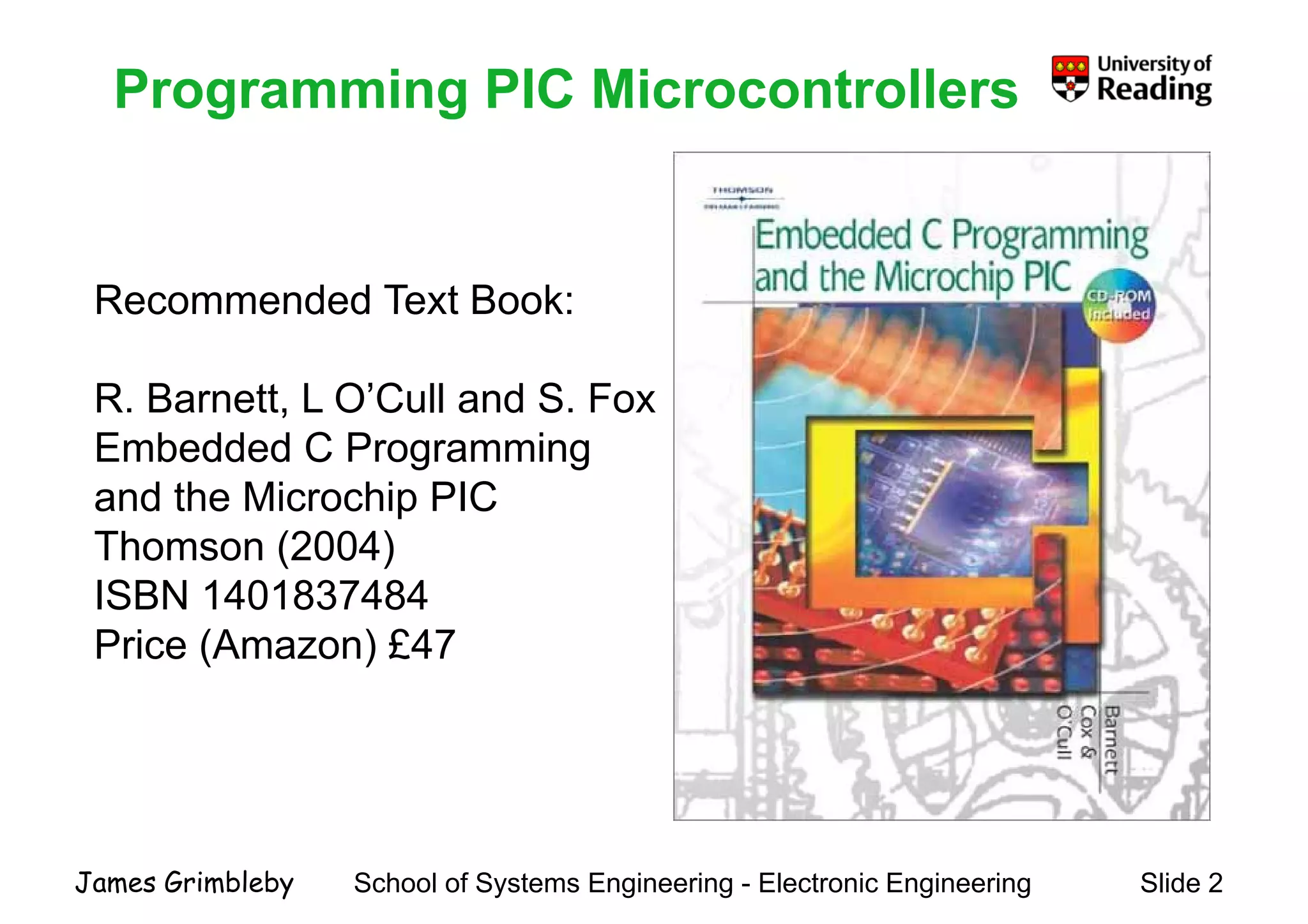
    Programming PIC MicrocontrollersProgrammingPIC Microcontrollers Recommended Text Book:Recommended Text Book: R. Barnett, L O’Cull and S. FoxR. Barnett, L O Cull and S. Fox Embedded C Programming and the Microchip PICp Thomson (2004) ISBN 1401837484 Price (Amazon) £47 School of Systems Engineering - Electronic Engineering Slide 2James Grimbleby
  • 3.
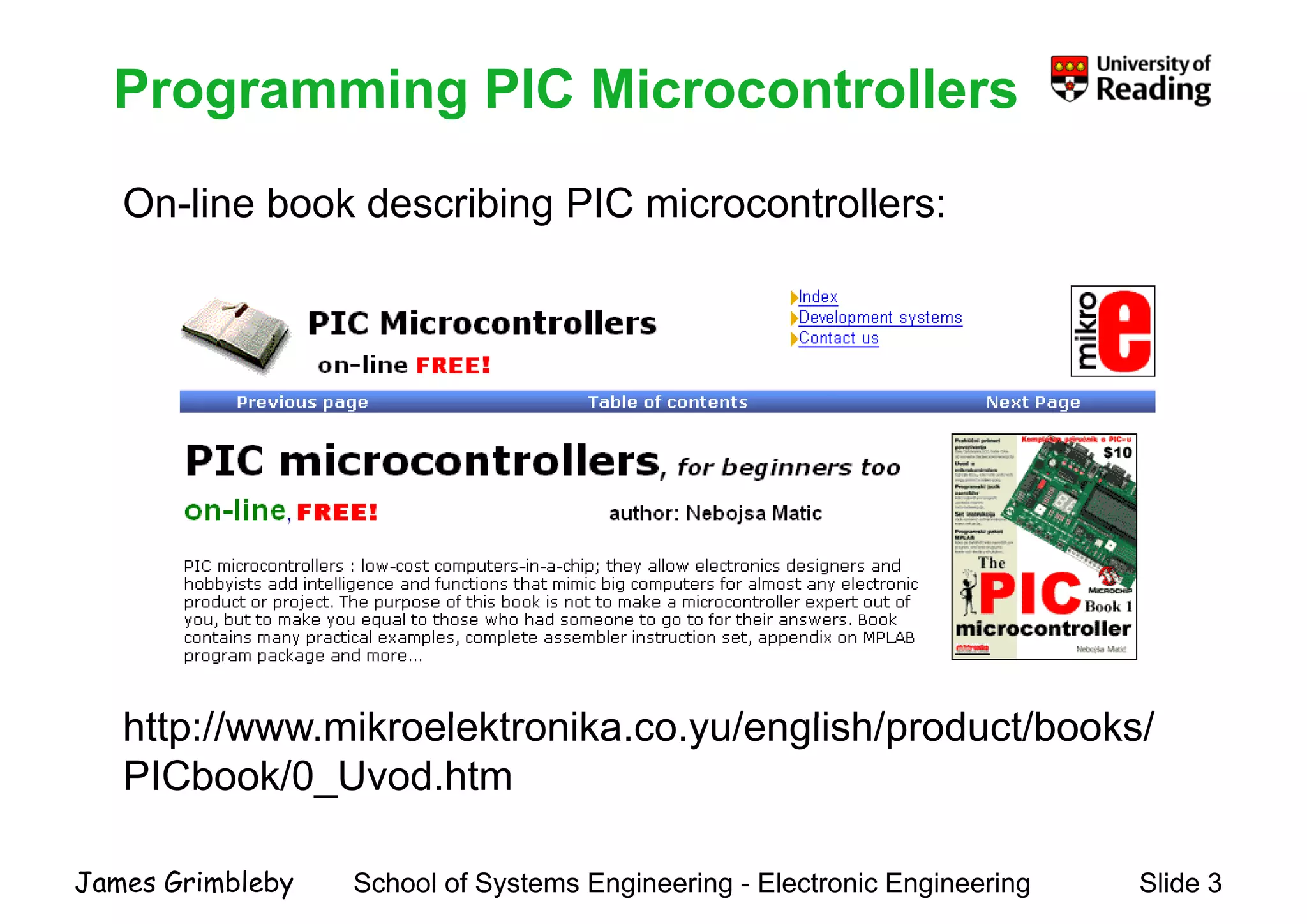
    Programming PIC Microcontrollers On-linebook describing PIC microcontrollers: Programming PIC Microcontrollers On-line book describing PIC microcontrollers: htt // ik l kt ik / li h/ d t/b k /http://www.mikroelektronika.co.yu/english/product/books/ PICbook/0_Uvod.htm School of Systems Engineering - Electronic Engineering Slide 3James Grimbleby
  • 4.
    Programming PIC MicrocontrollersProgrammingPIC Microcontrollers Manual for CCS PICManual for CCS PIC C compiler: http://www ccsinfo com/downloads/ccs c manual pdf School of Systems Engineering - Electronic Engineering Slide 4James Grimbleby http://www.ccsinfo.com/downloads/ccs_c_manual.pdf
  • 5.
    Programming PIC MicrocontrollersProgrammingPIC Microcontrollers This course is about programming PIC microcontrollers in C using the CCS PIC-C compiler Topics covered include: PIC architecture PIC specific limitations and extensions to CPIC-specific limitations and extensions to C Programming PIC hardware such as ports, ADC, timers, etc Using software librariesUsing software libraries You should already be familiar with the C and C++You should already be familiar with the C and C++ programming languages School of Systems Engineering - Electronic Engineering Slide 5James Grimbleby
  • 6.
    Assessment This nit illbe assessed b a m ltiple choice test Assessment This unit will be assessed by a multiple-choice test The multiple choice test will last for 30 minutes during whichThe multiple-choice test will last for 30 minutes, during which 20 questions must be answered You will be permitted to bring your notebooks and the course notes into the testnotes into the test The test will be held at the end of the Autumn termThe test will be held at the end of the Autumn term The marks from this test will contribute to the overall mark forThe marks from this test will contribute to the overall mark for the module EE2A2 School of Systems Engineering - Electronic Engineering Slide 6James Grimbleby
  • 7.
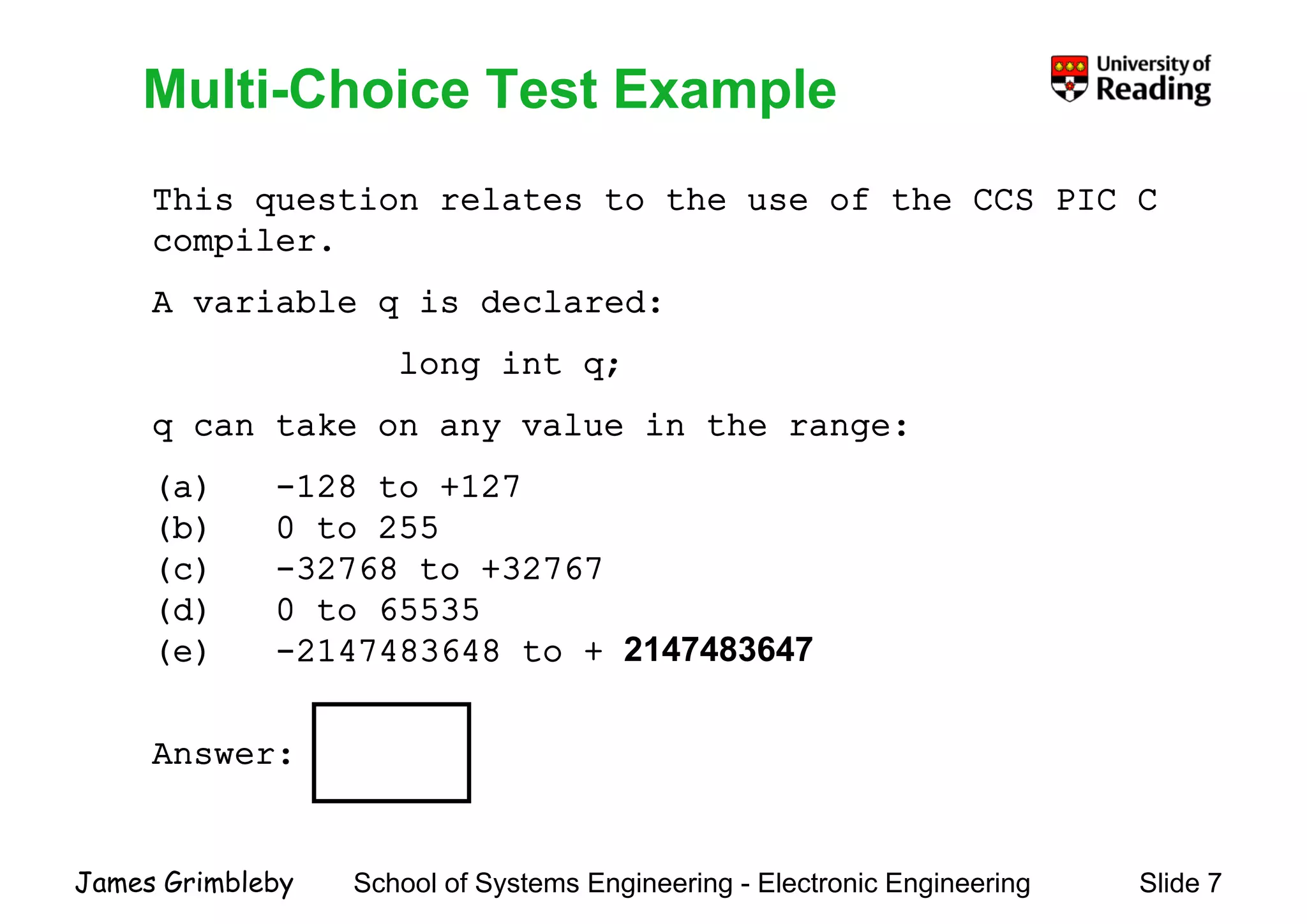
    Multi-Choice Test Example Thisquestion relates to the use of the CCS PIC C Multi Choice Test Example This question relates to the use of the CCS PIC C compiler. A variable q is declared:A variable q is declared: long int q; k l i hq can take on any value in the range: (a) -128 to +127 (b) 0 2(b) 0 to 255 (c) -32768 to +32767 (d) 0 to 65535(d) 0 to 65535 (e) -2147483648 to + 2147483647 Answer: School of Systems Engineering - Electronic Engineering Slide 7James Grimbleby
  • 8.
    Programming PIC MicrocontrollersProgrammingPIC Microcontrollers Lecture 1 PIC ArchitecturePIC Architecture School of Systems Engineering - Electronic Engineering Slide 8James Grimbleby
  • 9.
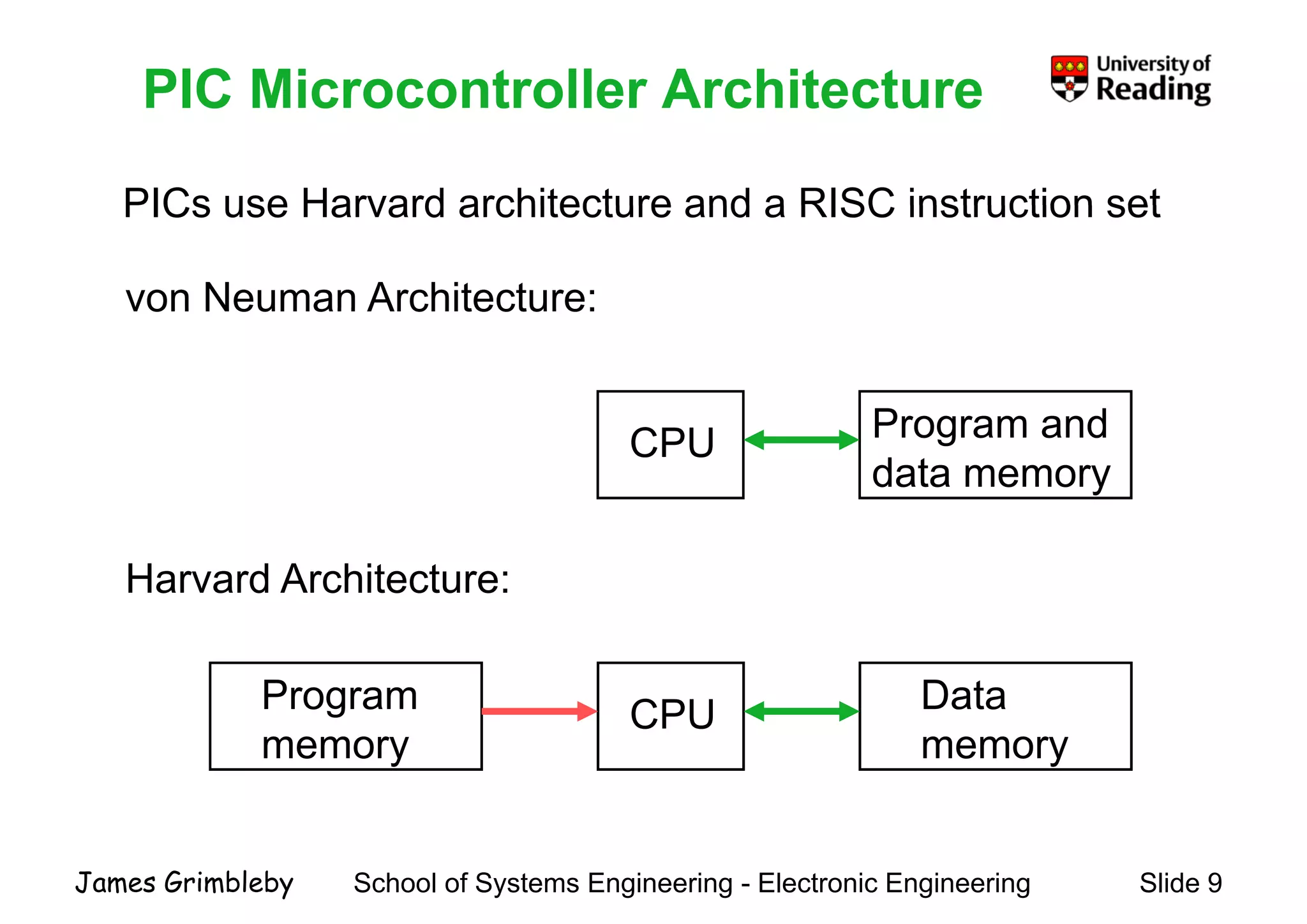
    PIC Microcontroller Architecture PICsuse Harvard architecture and a RISC instruction set PIC Microcontroller Architecture PICs use Harvard architecture and a RISC instruction set von Neuman Architecture: P d von Neuman Architecture: CPU Program and data memory Harvard Architecture: CPU DataProgram CPU memorymemory School of Systems Engineering - Electronic Engineering Slide 9James Grimbleby
  • 10.
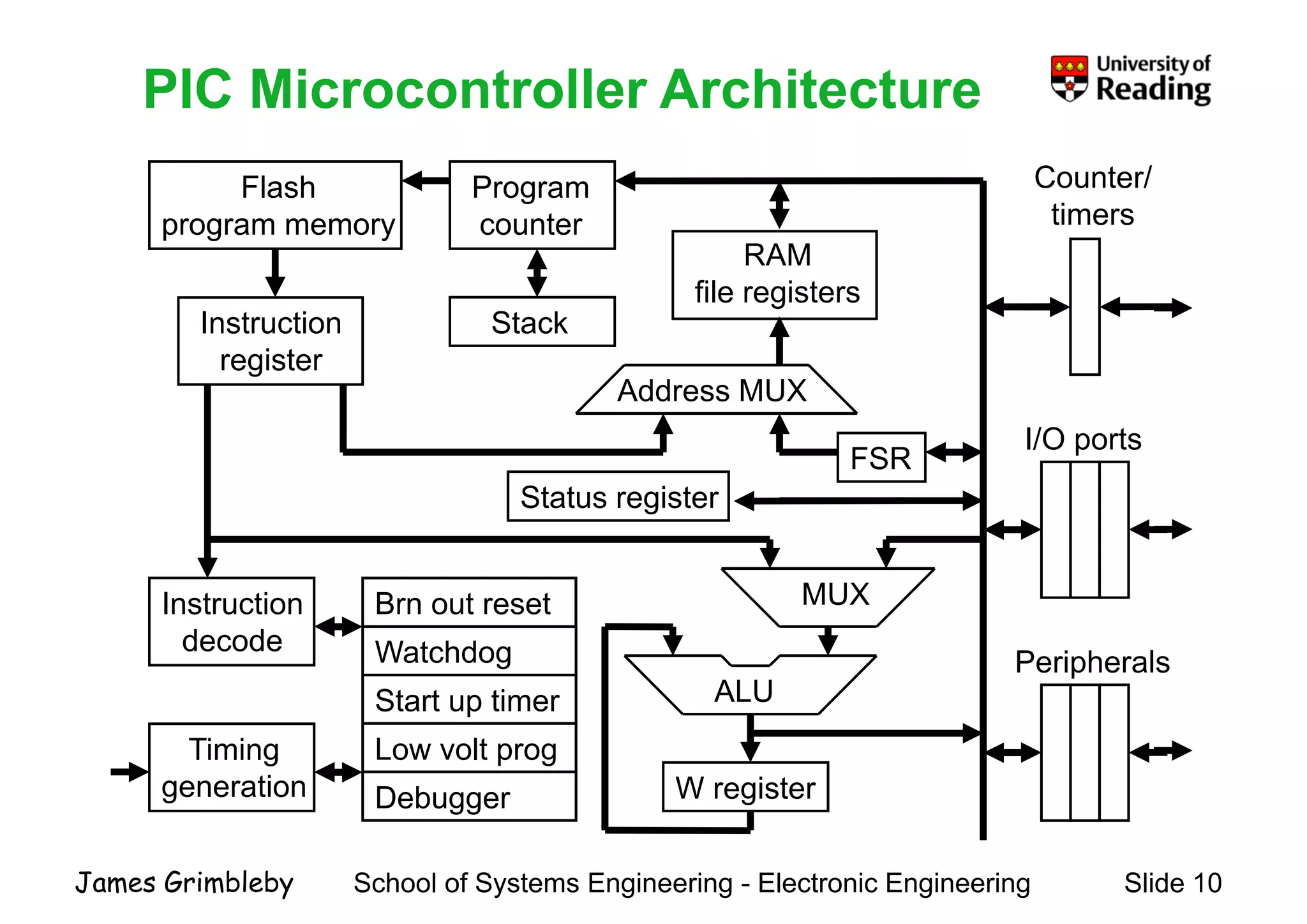
    PIC Microcontroller ArchitecturePICMicrocontroller Architecture Flash Program Counter/ tiprogram memory RAM file registers counter timers g Instruction register Address MUX Stack FSR Status register I/O ports Brn out reset g Instruction MUX Start up timer Watchdog ALU decode Peripherals W register Timing generation Low volt prog Debugger School of Systems Engineering - Electronic Engineering Slide 10James Grimbleby
  • 11.
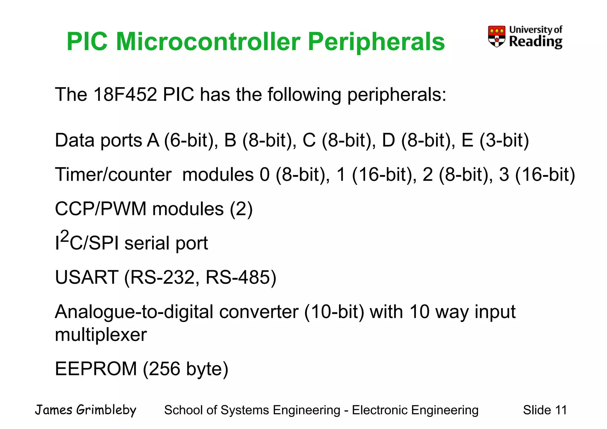
    PIC Microcontroller Peripherals The18F452 PIC has the following peripherals: PIC Microcontroller Peripherals The 18F452 PIC has the following peripherals: Data ports A (6-bit) B (8-bit) C (8-bit) D (8-bit) E (3-bit)Data ports A (6 bit), B (8 bit), C (8 bit), D (8 bit), E (3 bit) Timer/counter modules 0 (8-bit), 1 (16-bit), 2 (8-bit), 3 (16-bit) CCP/PWM modules (2) I2C/SPI i l tI2C/SPI serial port USART (RS-232, RS-485)( , ) Analogue-to-digital converter (10-bit) with 10 way input multiplexermultiplexer EEPROM (256 byte) School of Systems Engineering - Electronic Engineering Slide 11James Grimbleby
  • 12.
    Clock Generator PICs usea fully static design so that any clock frequency up Clock Generator PICs use a fully static design so that any clock frequency up to the specified maximum can be used There are 4 possible clock configurations: external clock (eg crystal oscillator module)- external clock (eg crystal oscillator module) - self-oscillating with external crystal or ceramic resonator - external or self-oscillating with phase-locked loop - self-oscillating with external RC In practice the choice will normally be a compromise between cost and clock speed or clock stability School of Systems Engineering - Electronic Engineering Slide 12James Grimbleby
  • 13.
    Reset A reset putsthe PIC in a well-defined initial state so that the Reset p processor starts executing code from the first instruction Resets can result from: - external reset by MCLR pulled low- external reset by MCLR pulled low - reset on power-up - reset by watchdog timer overflow t l b t- reset on power supply brown-out Reset can be sed as a last resort for reco ering from someReset can be used as a last resort for recovering from some catastrophic software event but all current data will be lost School of Systems Engineering - Electronic Engineering Slide 13James Grimbleby
  • 14.
    Central Processing UnitCentralProcessing Unit The CPU fetches instructions from memory, decodes them, and passes them to the ALU for execution The arithmetic logic unit (ALU) is responsible for adding, subtracting, shifting and performing logical operations Th ALU i j i i hThe ALU operates in conjunction with: - a general-purpose register called the W register - an f register that can be any location in data memory lit l b dd d i th i t ti d- literals embedded in the instruction code School of Systems Engineering - Electronic Engineering Slide 14James Grimbleby
  • 15.
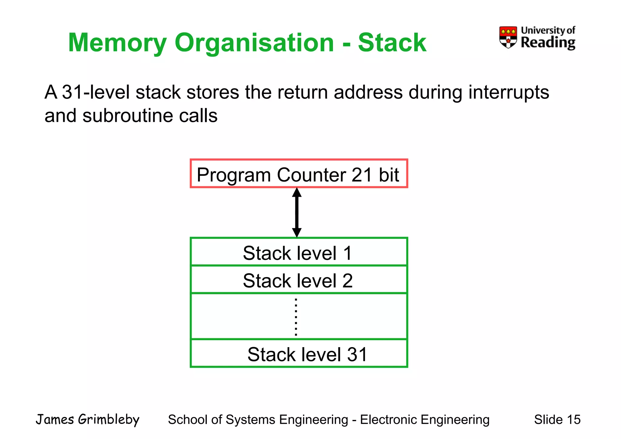
    Memory Organisation -Stack A 31-level stack stores the return address during interrupts Memory Organisation Stack A 31 level stack stores the return address during interrupts and subroutine calls Program Counter 21 bit Stack level 1 Stack level 2 ....... Stack level 31 School of Systems Engineering - Electronic Engineering Slide 15James Grimbleby
  • 16.
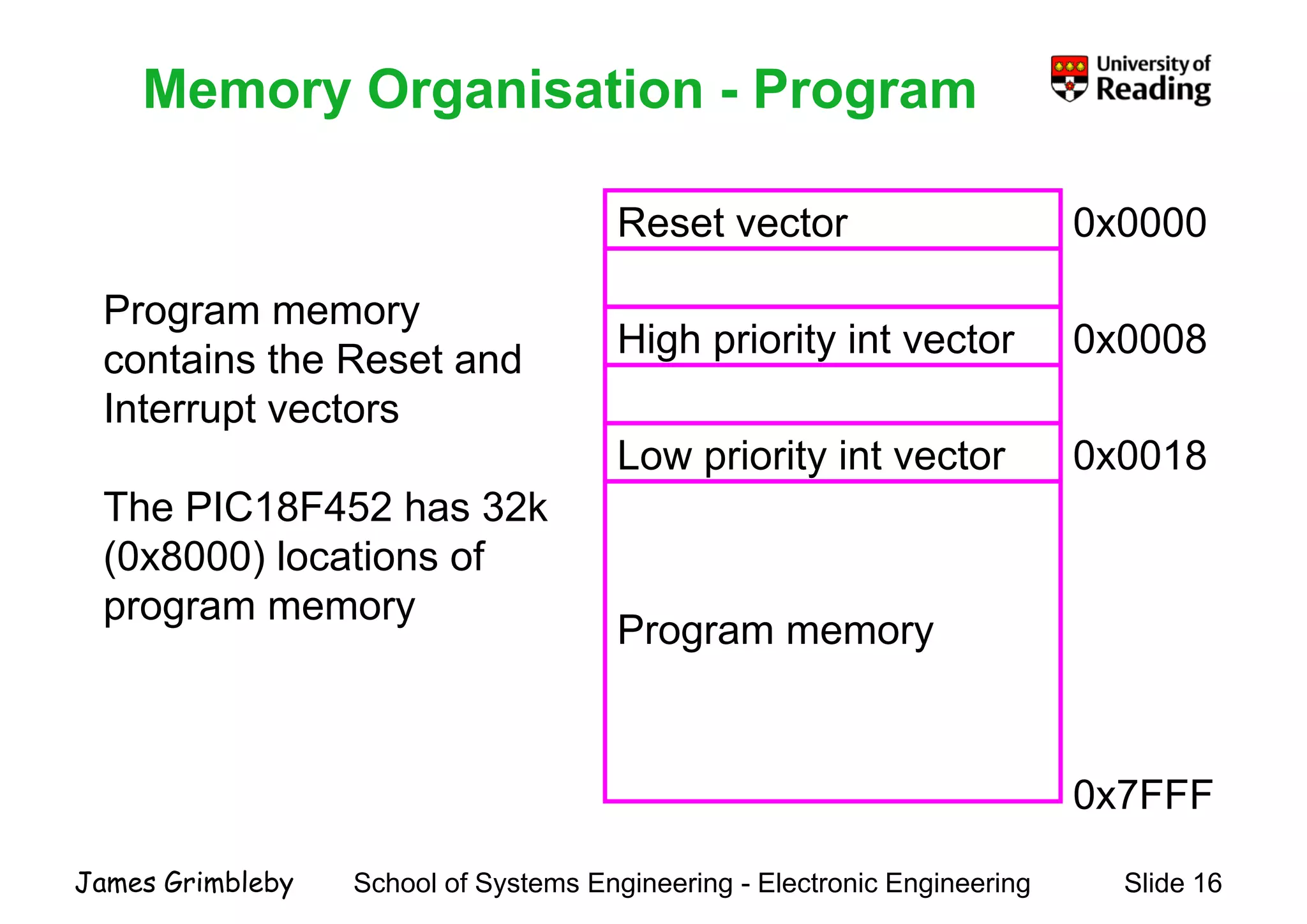
    Memory Organisation -ProgramMemory Organisation Program Reset vector 0x0000 Program memory High priority int vector 0x0008 Program memory contains the Reset and Interrupt vectors Low priority int vector 0x0018 Interrupt vectors The PIC18F452 has 32k P The PIC18F452 has 32k (0x8000) locations of program memory Program memory program memory 0x7FFF School of Systems Engineering - Electronic Engineering Slide 16James Grimbleby
  • 17.
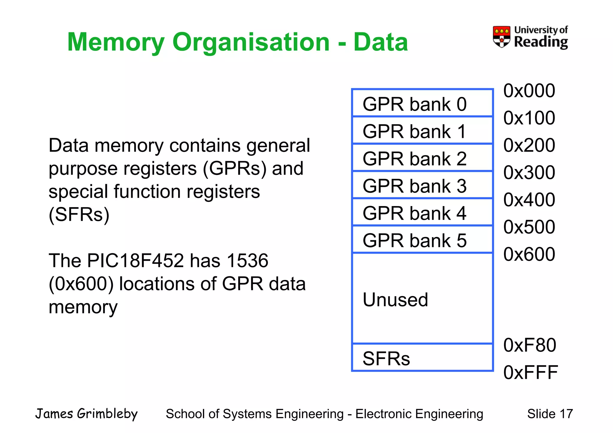
    Memory Organisation -Data 0x000 Memory Organisation Data Data memory contains general GPR bank 0 0x000 0x100 GPR bank 1 0x200Data memory contains general purpose registers (GPRs) and special function registers GPR bank 2 GPR bank 3 0x200 0x300 special function registers (SFRs) GPR bank 3 GPR bank 4 GPR bank 5 0x400 0x500 The PIC18F452 has 1536 (0x600) locations of GPR data GPR bank 5 0x600 (0x600) locations of GPR data memory Unused 0xFFF 0xF80 SFRs School of Systems Engineering - Electronic Engineering Slide 17James Grimbleby
  • 18.
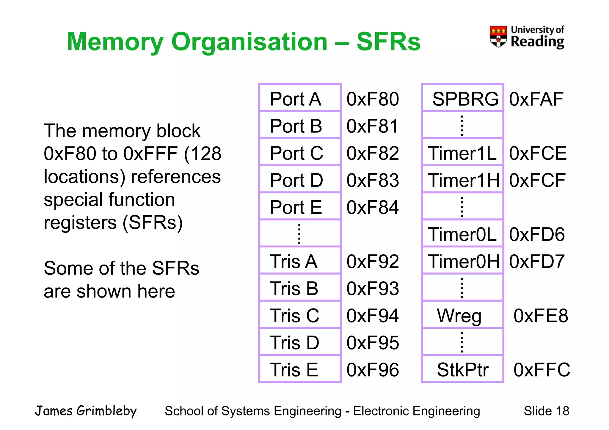
    Memory Organisation –SFRs Port A 0 F80 SPBRG 0 FAF Memory Organisation SFRs The memory block Port A 0xF80 0xF81Port B SPBRG 0xFAF ..... 0xF80 to 0xFFF (128 locations) references Port C Port D 0xF82 0xF83 Timer1L 0xFCE 0xFCFTimer1H special function registers (SFRs) Port E .... 0xF84 Timer0L ..... 0xFD6 Some of the SFRs h h .. 0xF93 0xF92Tris A Tris B Timer0L 0xFD6 0xFD7Timer0H .. are shown here 0xF93Tris B Tris C 0xF94 Wreg 0xFE8 ... . Tris D Tris E 0xF95 0xF96 StkPtr 0xFFC ..... School of Systems Engineering - Electronic Engineering Slide 18James Grimbleby
  • 19.
    PIC Instruction Set ThePIC instruction set has a small number of simple (RISC) PIC Instruction Set The PIC instruction set has a small number of simple (RISC) instructions PIC16 series: 35 instructions coded into 14 bits PIC 18 series: 59 instructions coded into 16 bitsPIC 18 series: 59 instructions coded into 16 bits PIC 24 series: 71 instructions coded into 24 bits Most instructions are executed in one instruction cycle which corresponds to 4 clock cycles Thus a PIC operating at 40 MHz clock frequency will have an instruction rate of 10 MIPS. School of Systems Engineering - Electronic Engineering Slide 19James Grimbleby
  • 20.
    PIC 18Fxxx InstructionSet Most PIC 18Fxxx instructions occupy a single 16-bit program PIC 18Fxxx Instruction Set memory location Each instruction consists of an opcode and one or moreEach instruction consists of an opcode and one or more operands The instruction set is highly orthogonal and can be partitioned:partitioned: - 31 byte-oriented file register operations - 5 bit-oriented file register operations - 23 control instructions - 10 literal instructions - 8 data memory – program memory operations School of Systems Engineering - Electronic Engineering Slide 20James Grimbleby 8 data memory program memory operations
  • 21.
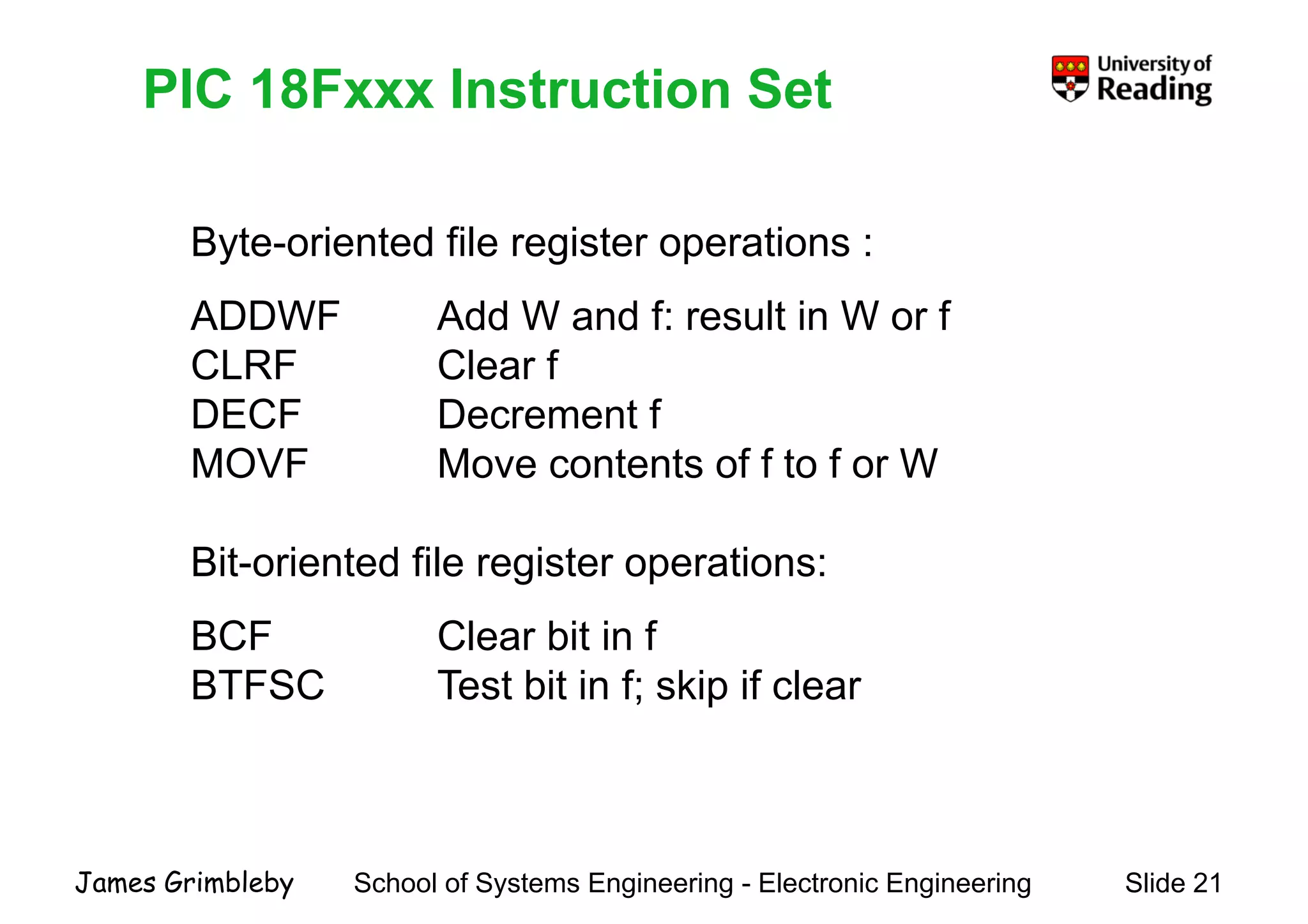
    PIC 18Fxxx InstructionSetPIC 18Fxxx Instruction Set Byte-oriented file register operations : ADDWF Add W d f lt i W fADDWF Add W and f: result in W or f CLRF Clear f DECF Decrement fDECF Decrement f MOVF Move contents of f to f or W Bit-oriented file register operations: BCF Clear bit in f BTFSC Test bit in f; skip if clear School of Systems Engineering - Electronic Engineering Slide 21James Grimbleby
  • 22.
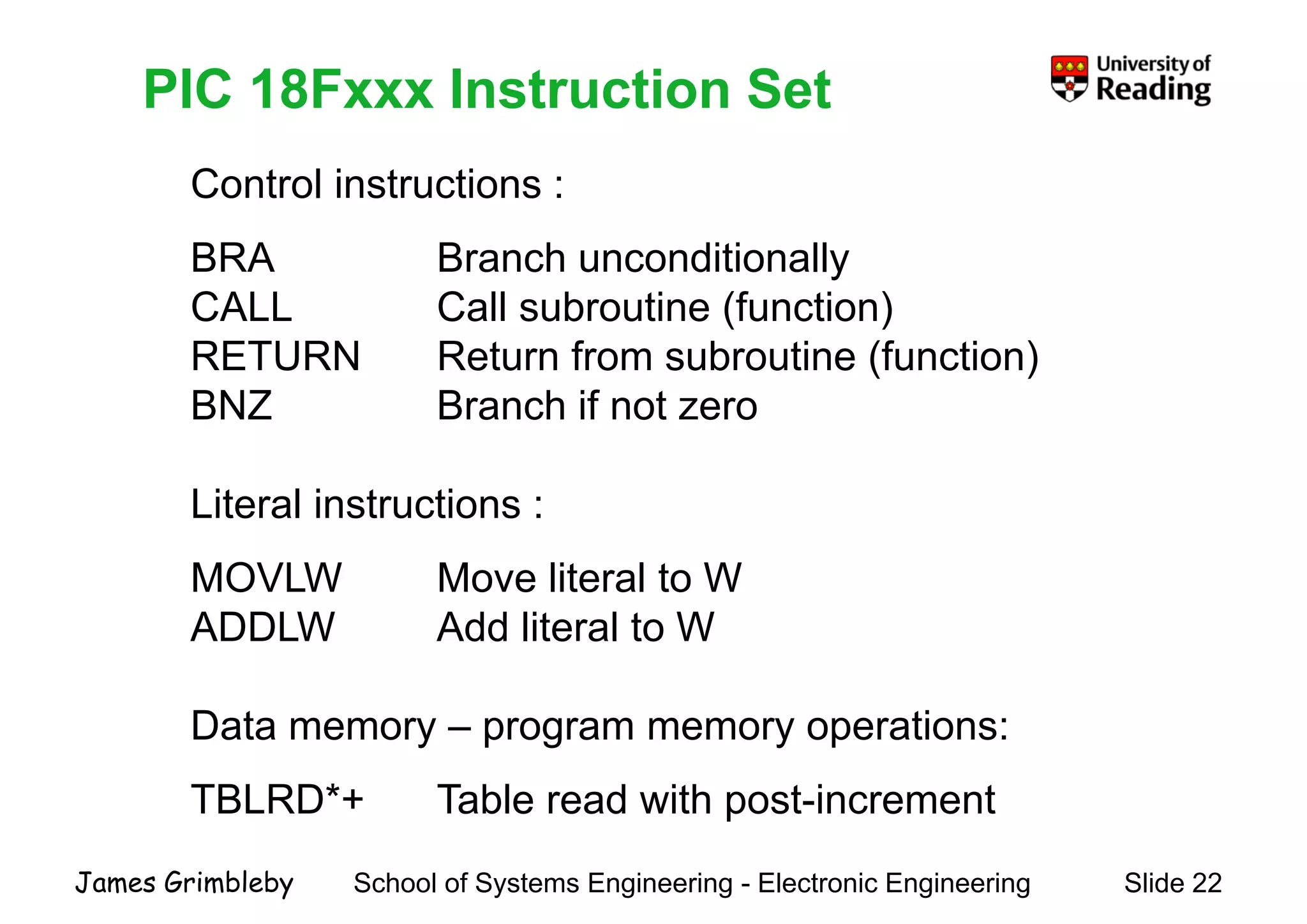
    PIC 18Fxxx InstructionSet Control instructions : PIC 18Fxxx Instruction Set BRA Branch unconditionally CALL Call subroutine (function)CALL Call subroutine (function) RETURN Return from subroutine (function) BNZ Branch if not zeroBNZ Branch if not zero Literal instructions :Literal instructions : MOVLW Move literal to W ADDLW Add lit l t WADDLW Add literal to W Data memor program memor operationsData memory – program memory operations: TBLRD*+ Table read with post-increment School of Systems Engineering - Electronic Engineering Slide 22James Grimbleby p
  • 23.
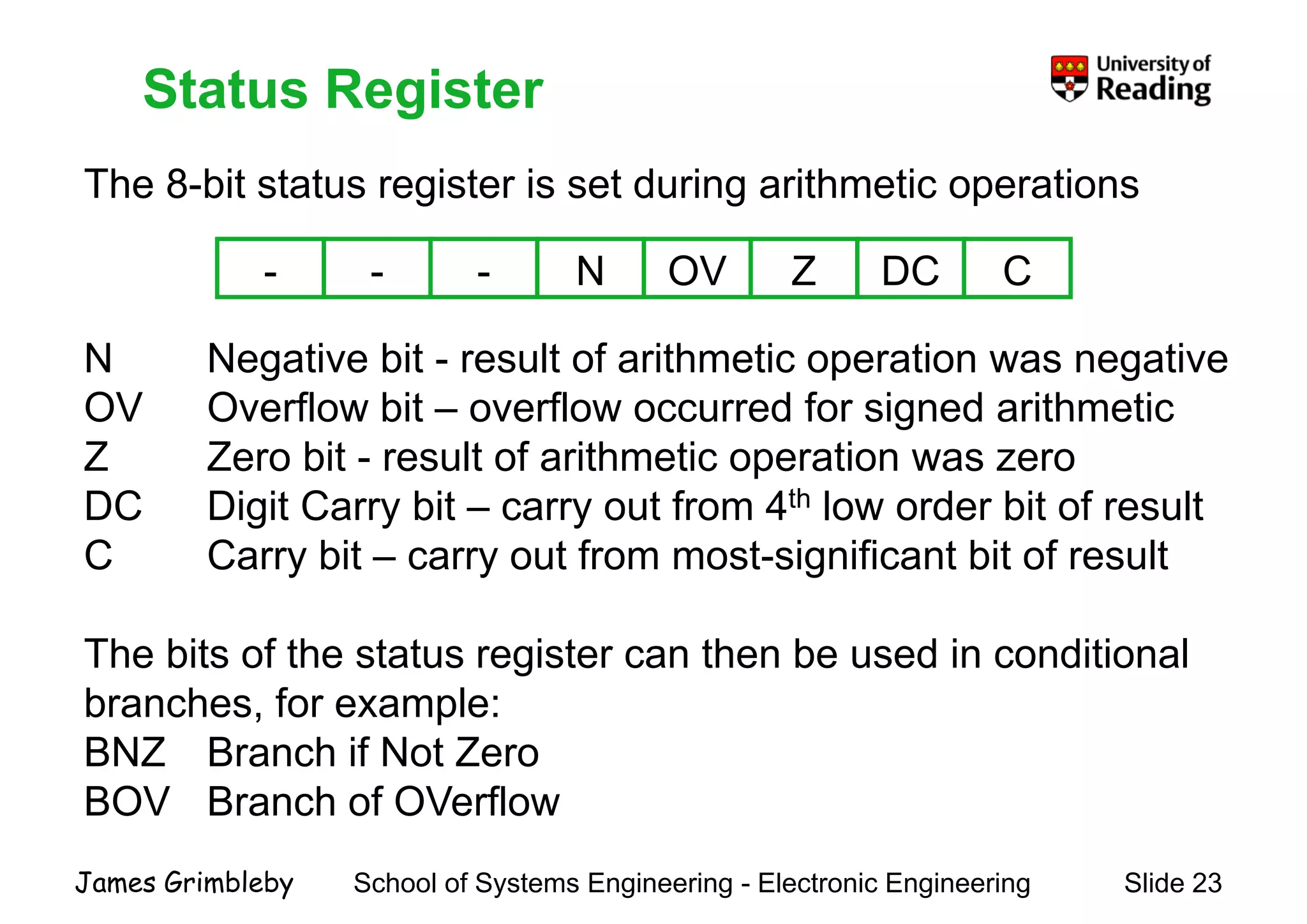
    Status Register The 8-bitstatus register is set during arithmetic operations Status Register - - - N OV Z DC C g g p N Negative bit - result of arithmetic operation was negative OV Overflow bit – overflow occurred for signed arithmeticOV Overflow bit – overflow occurred for signed arithmetic Z Zero bit - result of arithmetic operation was zero DC Digit Carry bit – carry out from 4th low order bit of resultDC Digit Carry bit carry out from 4 low order bit of result C Carry bit – carry out from most-significant bit of result The bits of the status register can then be used in conditional branches, for example:, p BNZ Branch if Not Zero BOV Branch of OVerflow School of Systems Engineering - Electronic Engineering Slide 23James Grimbleby
  • 24.
    Programming PIC MicrocontrollersProgrammingPIC Microcontrollers Lecture 2 CCS CompilerCCS Compiler School of Systems Engineering - Electronic Engineering Slide 24James Grimbleby
  • 25.
    What is C? In 1970 a team at Bell Labs led by Brian Kernighan were What is C ? y g developing the UNIX computer operating system They required a high-level computer language for writing computer operating systems Starting from an existing language called BCPL they Cdeveloped C C d t it th t i f UNIX tC was used to write the next version of UNIX system software UNIX eventually became the world's first portable operating system School of Systems Engineering - Electronic Engineering Slide 25James Grimbleby system
  • 26.
    What is C? C has now become a widely used professional language for What is C ? y p g g various reasons: It h hi h l l t tIt has high level constructs It can handle low level activities It produces efficient programs It can be compiled on a wide variety of computersIt can be compiled on a wide variety of computers The standard for C programs was originally the features setThe standard for C programs was originally the features set by Brian Kernighan Later an international standard was developed: ANSI C (American National Standards Institute) School of Systems Engineering - Electronic Engineering Slide 26James Grimbleby (American National Standards Institute)
  • 27.
    What is C++? More recently another group at AT&T led by Bjarne Stroustrup What is C ? More recently another group at AT&T led by Bjarne Stroustrup developed C to reflect modern programming techniques The new language was called C++ C++ has stronger type checking and supports object-oriented programming C++ may be considered in several ways.: An extension of C A "data abstraction" improvement on CA data abstraction improvement on C A base for "object oriented" programming School of Systems Engineering - Electronic Engineering Slide 27James Grimbleby
  • 28.
    Why Program PICsin C? C is a portable language, requiring minimal modification when Why Program PICs in C? p g g q g transferring programs from one processor to another Programming in a high-level language rather than assembler allows programs to be developed much more rapidly Typically a program which takes a few weeks in assembler C fcan be written in C in a few days Code efficiency of compiled C programs is typically 80% ofCode efficiency of compiled C programs is typically 80% of well-written assembler programs The related language C++ is too complex for use with the present generation of PICs School of Systems Engineering - Electronic Engineering Slide 28James Grimbleby p g
  • 29.
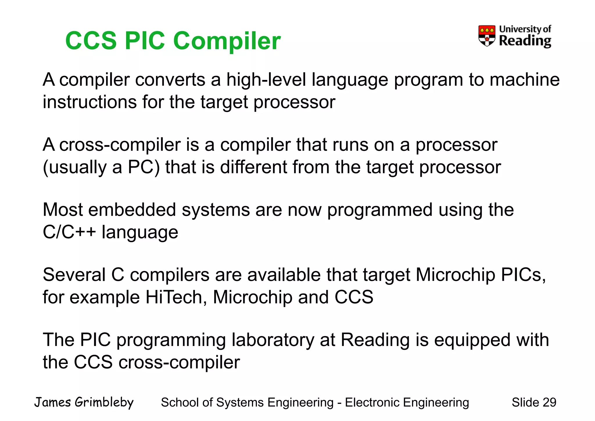
    CCS PIC Compiler Acompiler converts a high-level language program to machine CCS PIC Compiler instructions for the target processor A il i il th tA cross-compiler is a compiler that runs on a processor (usually a PC) that is different from the target processor Most embedded systems are now programmed using the C/C++ languageC/C++ language Several C compilers are available that target Microchip PICs,Several C compilers are available that target Microchip PICs, for example HiTech, Microchip and CCS The PIC programming laboratory at Reading is equipped with the CCS cross-compiler School of Systems Engineering - Electronic Engineering Slide 29James Grimbleby
  • 30.
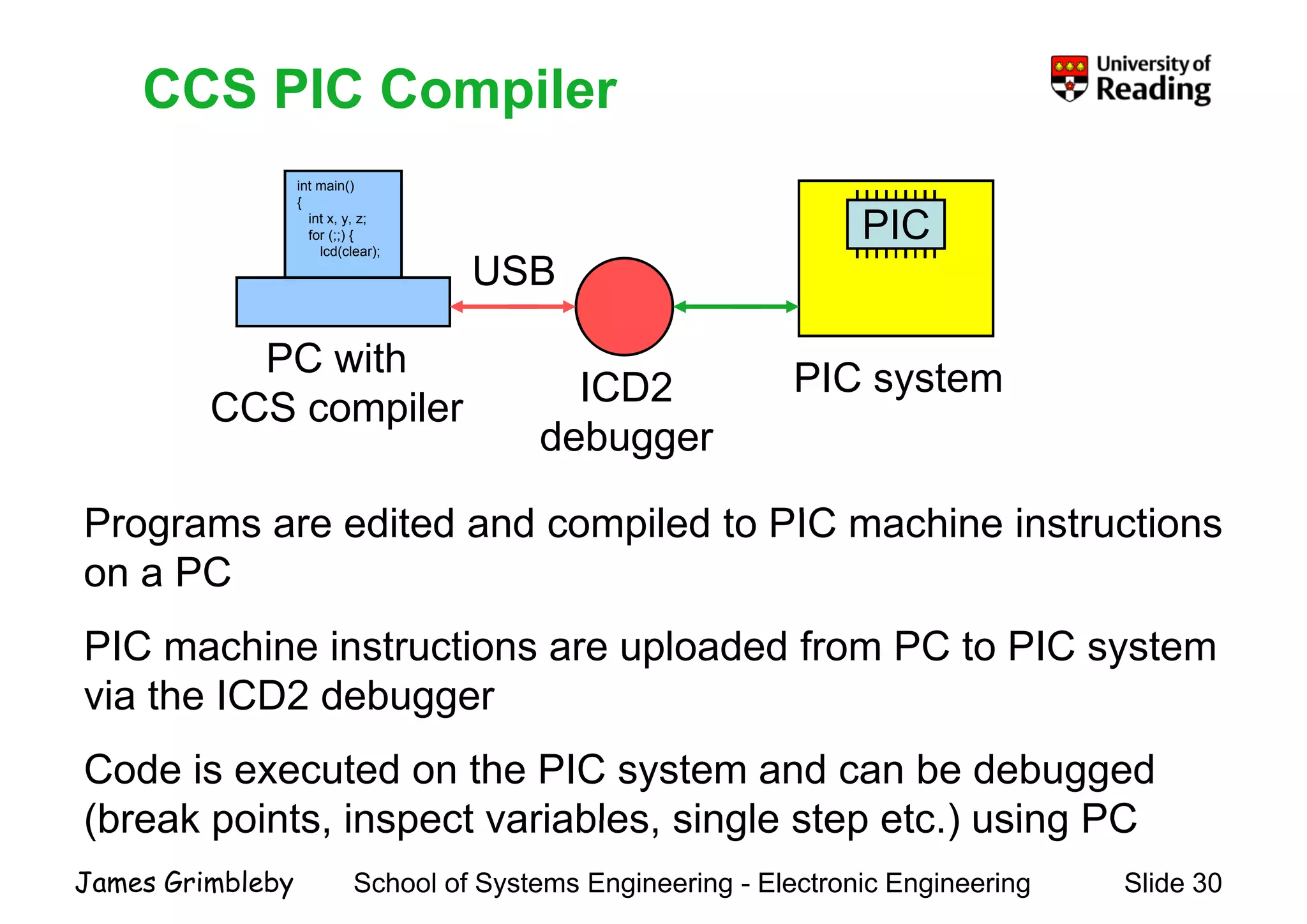
    CCS PIC Compiler intmain() { CCS PIC Compiler PIC { int x, y, z; for (;;) { lcd(clear); USB PC with CCS compiler ICD2 PIC system P dit d d il d t PIC hi i t ti CCS compiler debugger Programs are edited and compiled to PIC machine instructions on a PC PIC machine instructions are uploaded from PC to PIC system via the ICD2 debuggergg Code is executed on the PIC system and can be debugged (break points inspect variables single step etc ) using PC School of Systems Engineering - Electronic Engineering Slide 30James Grimbleby (break points, inspect variables, single step etc.) using PC
  • 31.
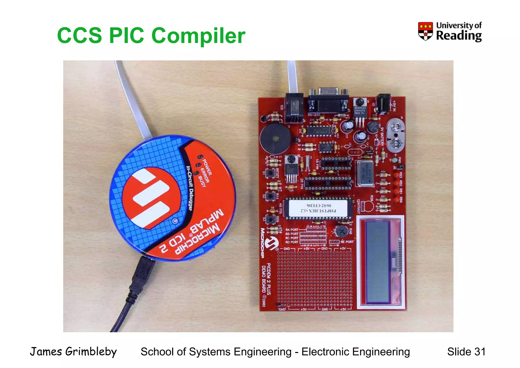
    CCS PIC CompilerCCSPIC Compiler School of Systems Engineering - Electronic Engineering Slide 31James Grimbleby
  • 32.
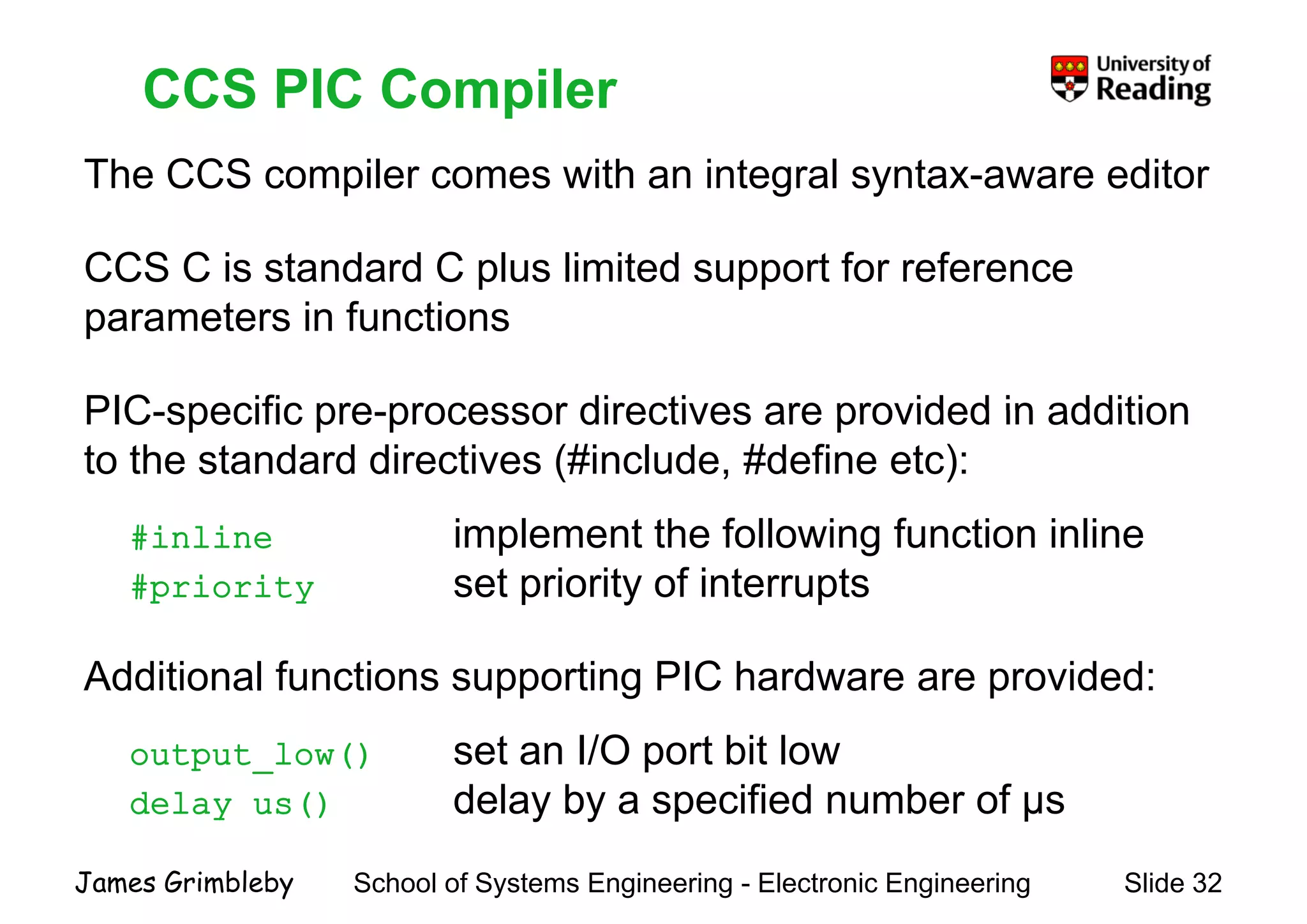
    CCS PIC Compiler TheCCS compiler comes with an integral syntax-aware editor CCS PIC Compiler CCS C is standard C plus limited support for reference t i f tiparameters in functions PIC specific pre processor directives are provided in additionPIC-specific pre-processor directives are provided in addition to the standard directives (#include, #define etc): #inline implement the following function inline #priority set priority of interrupts Additional functions supporting PIC hardware are provided: output_low() set an I/O port bit low delay_us() delay by a specified number of µs School of Systems Engineering - Electronic Engineering Slide 32James Grimbleby y y p µ
  • 33.
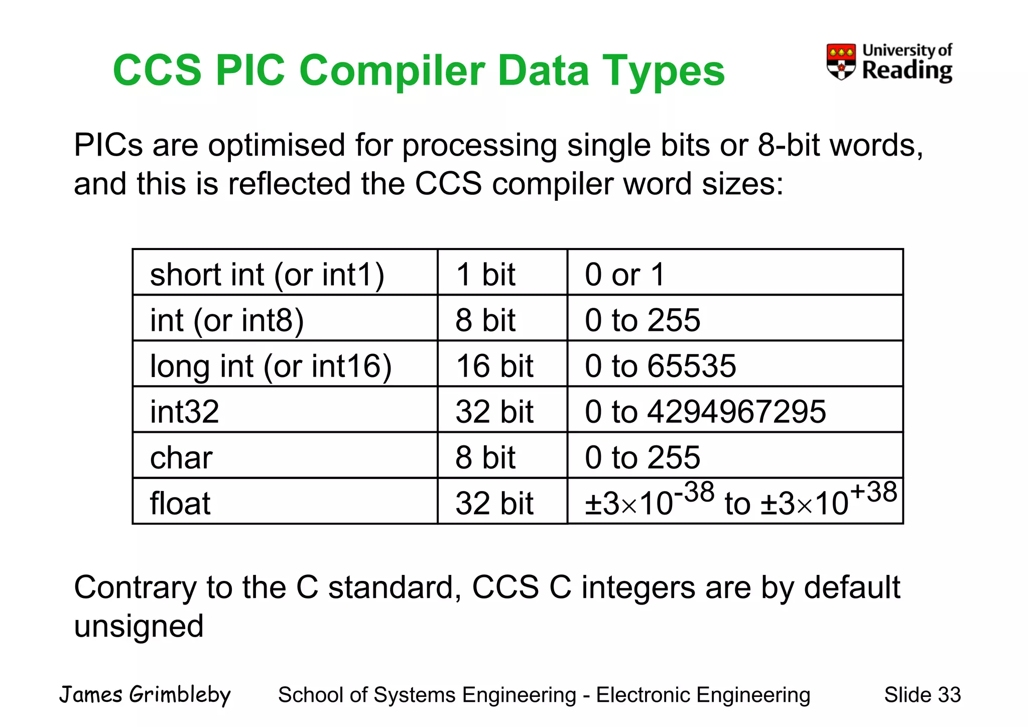
    CCS PIC CompilerData Types PICs are optimised for processing single bits or 8-bit words, CCS PIC Compiler Data Types p p g g and this is reflected the CCS compiler word sizes: short int (or int1) 1 bit int (or int8) 8 bit 0 or 1 0 to 255int (or int8) 8 bit long int (or int16) 16 bit i t32 32 bit 0 to 255 0 to 65535 0 t 4294967295int32 32 bit char 8 bit 0 to 4294967295 0 to 255 38 38float 32 bit ±3×10-38 to ±3×10+38 Contrary to the C standard, CCS C integers are by default unsigned School of Systems Engineering - Electronic Engineering Slide 33James Grimbleby
  • 34.
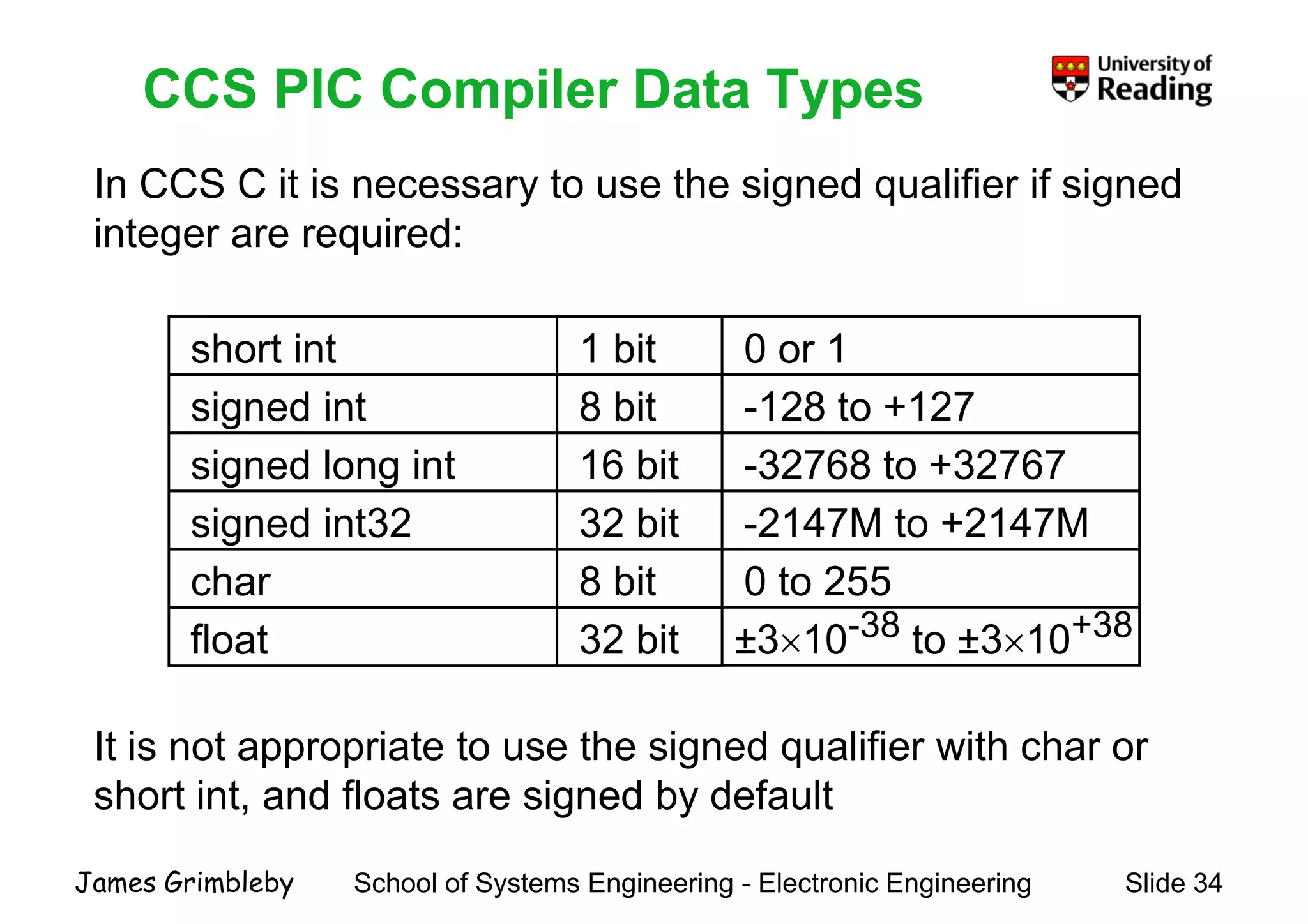
    CCS PIC CompilerData Types In CCS C it is necessary to use the signed qualifier if signed CCS PIC Compiler Data Types y g q g integer are required: short int 1 bit signed int 8 bit 0 or 1 -128 to +127signed int 8 bit signed long int 16 bit i d i t32 32 bit -128 to +127 -32768 to +32767 2147M t 2147Msigned int32 32 bit char 8 bit -2147M to +2147M 0 to 255 38 38float 32 bit ±3×10-38 to ±3×10+38 It is not appropriate to use the signed qualifier with char or short int, and floats are signed by default School of Systems Engineering - Electronic Engineering Slide 34James Grimbleby
  • 35.
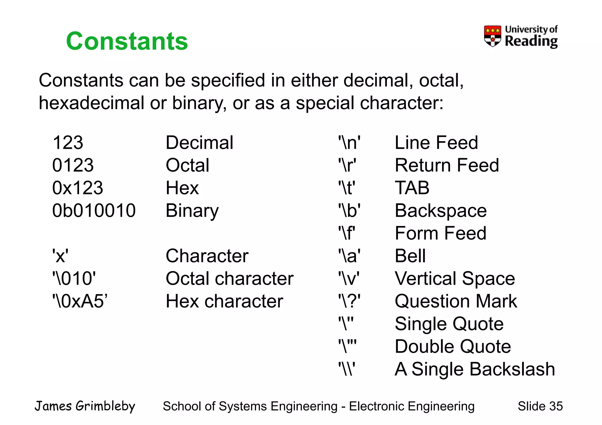
    Constants Constants can bespecified in either decimal, octal, Constants 123 Decimal 'n' Line Feed hexadecimal or binary, or as a special character: 123 Decimal 0123 Octal 0x123 Hex n Line Feed 'r' Return Feed 't' TAB0x123 Hex 0b010010 Binary t TAB 'b' Backspace 'f' Form Feed 'x' Character '010' Octal character f Form Feed 'a' Bell 'v' Vertical Space010 Octal character '0xA5’ Hex character v Vertical Space '?' Question Mark ''' Single Quote S g e Quote '"' Double Quote '' A Single Backslash School of Systems Engineering - Electronic Engineering Slide 35James Grimbleby g
  • 36.
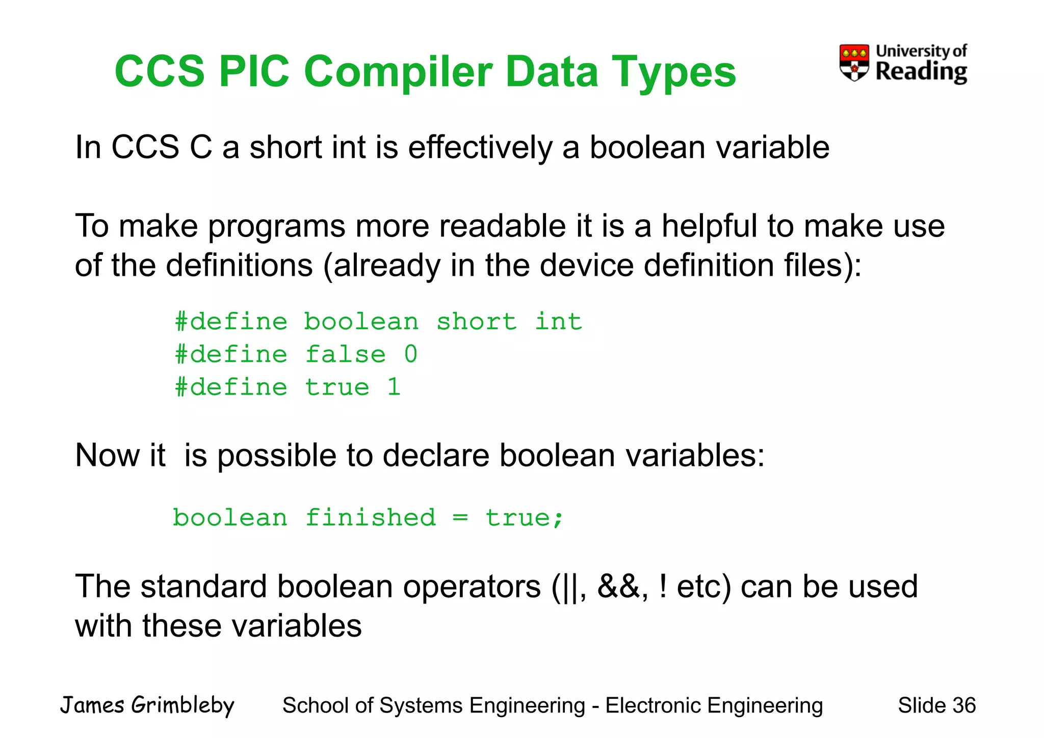
    CCS PIC CompilerData Types In CCS C a short int is effectively a boolean variable CCS PIC Compiler Data Types y To make programs more readable it is a helpful to make use of the definitions (already in the device definition files): #define boolean short int#define boolean short int #define false 0 #define true 1 Now it is possible to declare boolean variables: boolean finished = true; (|| && )The standard boolean operators (||, &&, ! etc) can be used with these variables School of Systems Engineering - Electronic Engineering Slide 36James Grimbleby
  • 37.
    Multi-Precision Operations It isoften necessary to process data words that are larger Multi Precision Operations It is often necessary to process data words that are larger than can be operated on by a single instruction PIC instructions only operate on 8-bit words Multi-precision arithmetic uses a sequence of basic instructions on existing data types In CCS C the long int (16 bit) and int32 (32 bit) types are processed using multi-precision arithmetic This is much more expensive in time and code size than single instructions School of Systems Engineering - Electronic Engineering Slide 37James Grimbleby
  • 38.
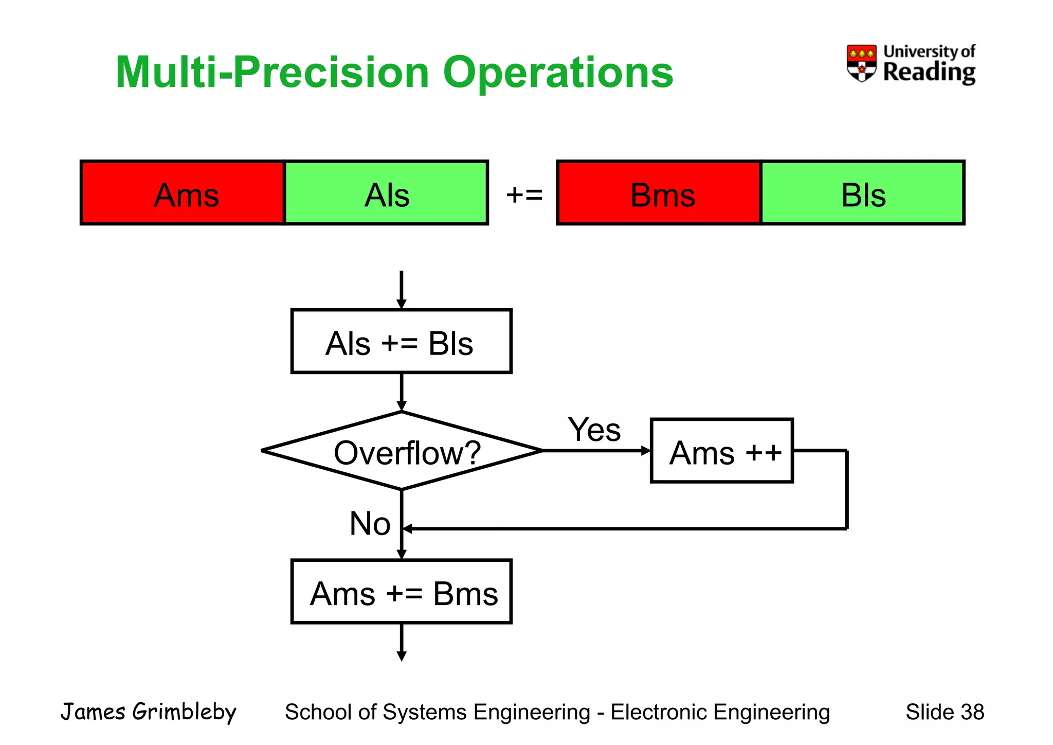
    Multi-Precision OperationsMulti PrecisionOperations Ams Als += Bms Bls Als += Bls Overflow? Ams ++ Yes No Ams += Bms School of Systems Engineering - Electronic Engineering Slide 38James Grimbleby
  • 39.
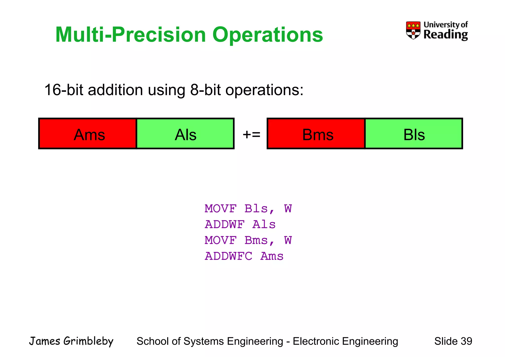
    Multi-Precision OperationsMulti PrecisionOperations 16-bit addition using 8-bit operations: Ams Als += Bms Bls MOVF Bls, W ADDWF Als MOVF Bms WMOVF Bms, W ADDWFC Ams School of Systems Engineering - Electronic Engineering Slide 39James Grimbleby
  • 40.
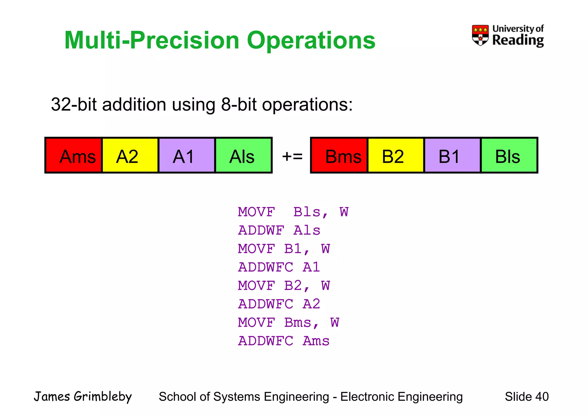
    Multi-Precision OperationsMulti PrecisionOperations 32-bit addition using 8-bit operations: Ams +=A2 A1 Als Bms B2 B1 Bls MOVF Bls, W ADDWF AlsADDWF Als MOVF B1, W ADDWFC A1 MOVF B2, W ADDWFC A2 MOVF Bms WMOVF Bms, W ADDWFC Ams School of Systems Engineering - Electronic Engineering Slide 40James Grimbleby
  • 41.
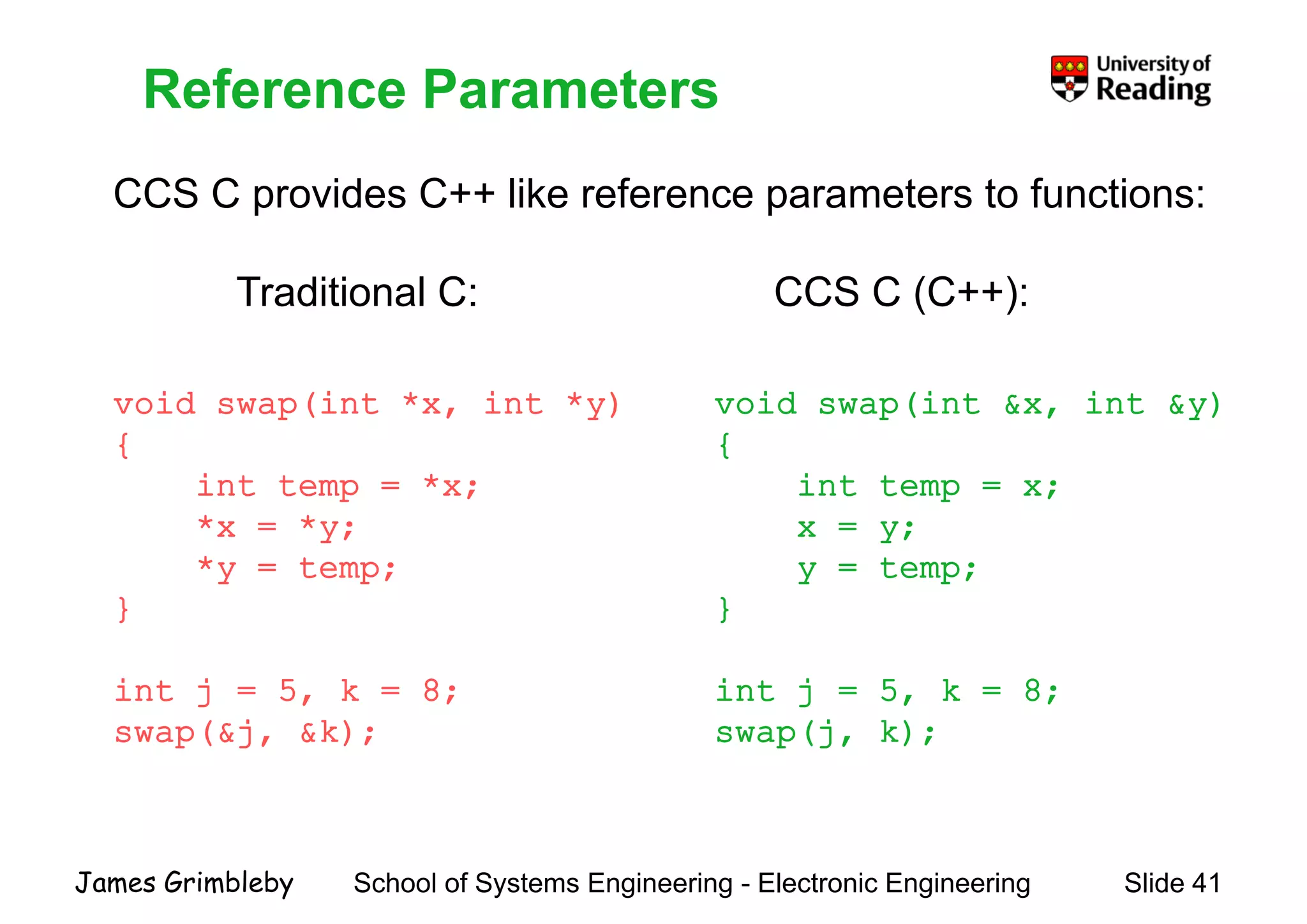
    Reference Parameters CCS Cprovides C++ like reference parameters to functions: Reference Parameters CCS C provides C like reference parameters to functions: Traditional C: CCS C (C++): void swap(int &x, int &y)void swap(int *x, int *y) ( ) void swap(int &x, int &y) { int temp = x; void swap(int x, int y) { int temp = *x; * * x = y; y = temp; } *x = *y; *y = temp; } } int j = 5, k = 8; (j k) } int j = 5, k = 8; (&j &k) swap(j, k);swap(&j, &k); School of Systems Engineering - Electronic Engineering Slide 41James Grimbleby
  • 42.
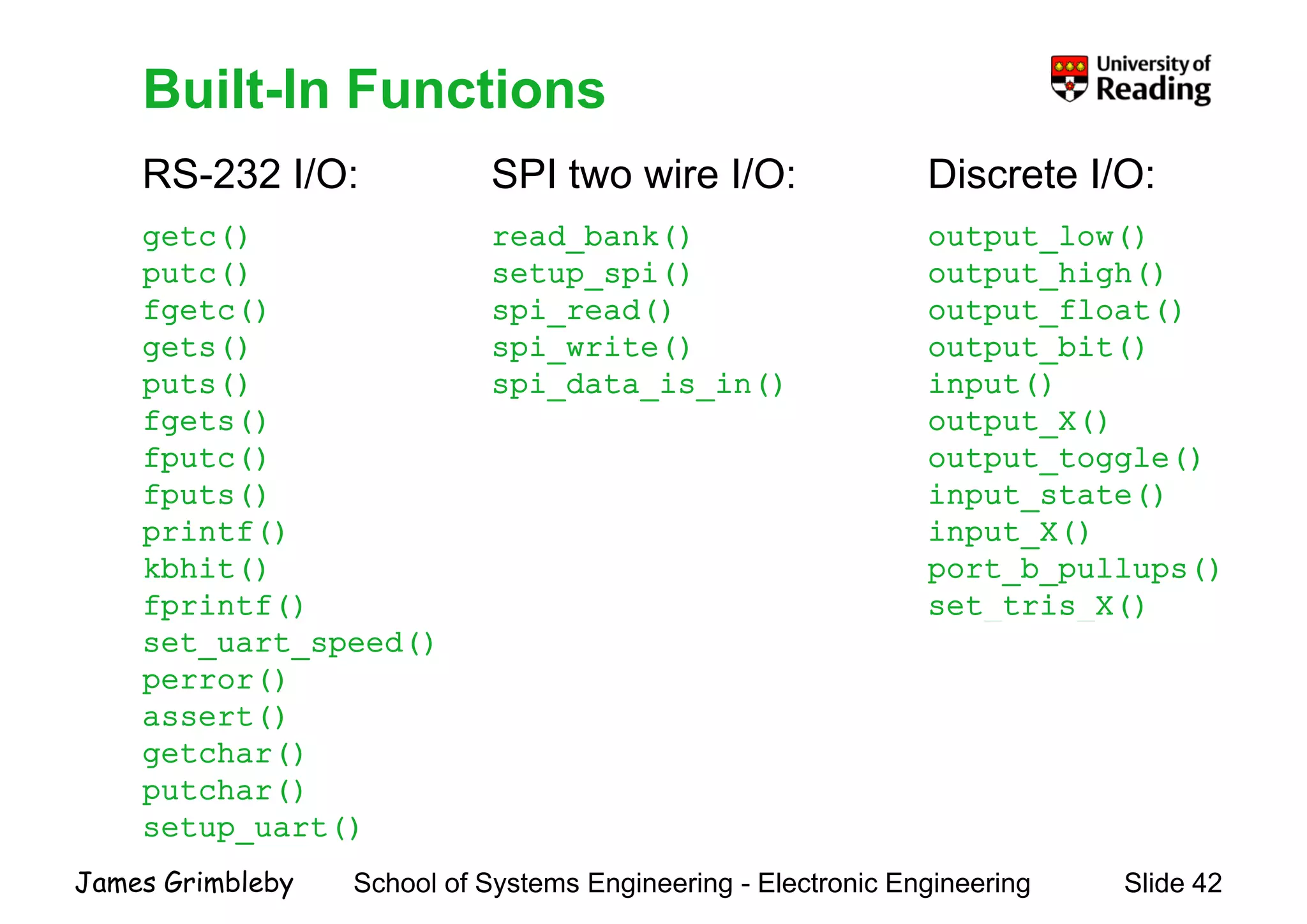
    Built-In Functions RS-232 I/O:SPI two wire I/O: Discrete I/O: Built In Functions getc() putc() fgetc() read_bank() setup_spi() spi read() output_low() output_high() output float()fgetc() gets() puts() f t () spi_read() spi_write() spi_data_is_in() output_float() output_bit() input() t t ()fgets() fputc() fputs() output_X() output_toggle() input_state() printf() kbhit() fprintf() input_X() port_b_pullups() set_tris_X()p () set_uart_speed() perror() assert() _ _ () assert() getchar() putchar() setup uart() School of Systems Engineering - Electronic Engineering Slide 42James Grimbleby setup_uart()
  • 43.
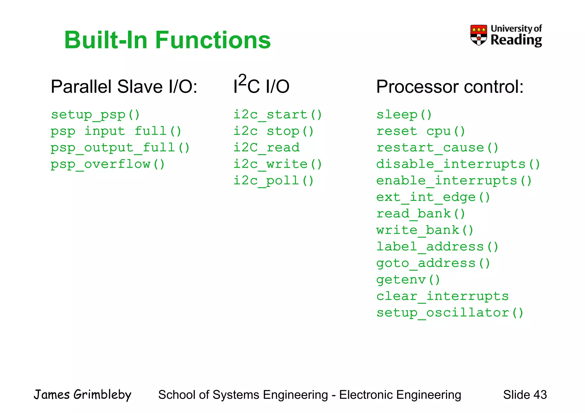
    Built-In Functions Parallel SlaveI/O: I2C I/O Processor control: Built In Functions Parallel Slave I/O: setup_psp() psp_input_full() I C I/O i2c_start() i2c_stop() Processor control: sleep() reset_cpu() psp_output_full() psp_overflow() i2C_read i2c_write() i2c poll() restart_cause() disable_interrupts() enable interrupts()i2c_poll() enable_interrupts() ext_int_edge() read_bank() write bank()write_bank() label_address() goto_address() t ()getenv() clear_interrupts setup_oscillator() School of Systems Engineering - Electronic Engineering Slide 43James Grimbleby
  • 44.
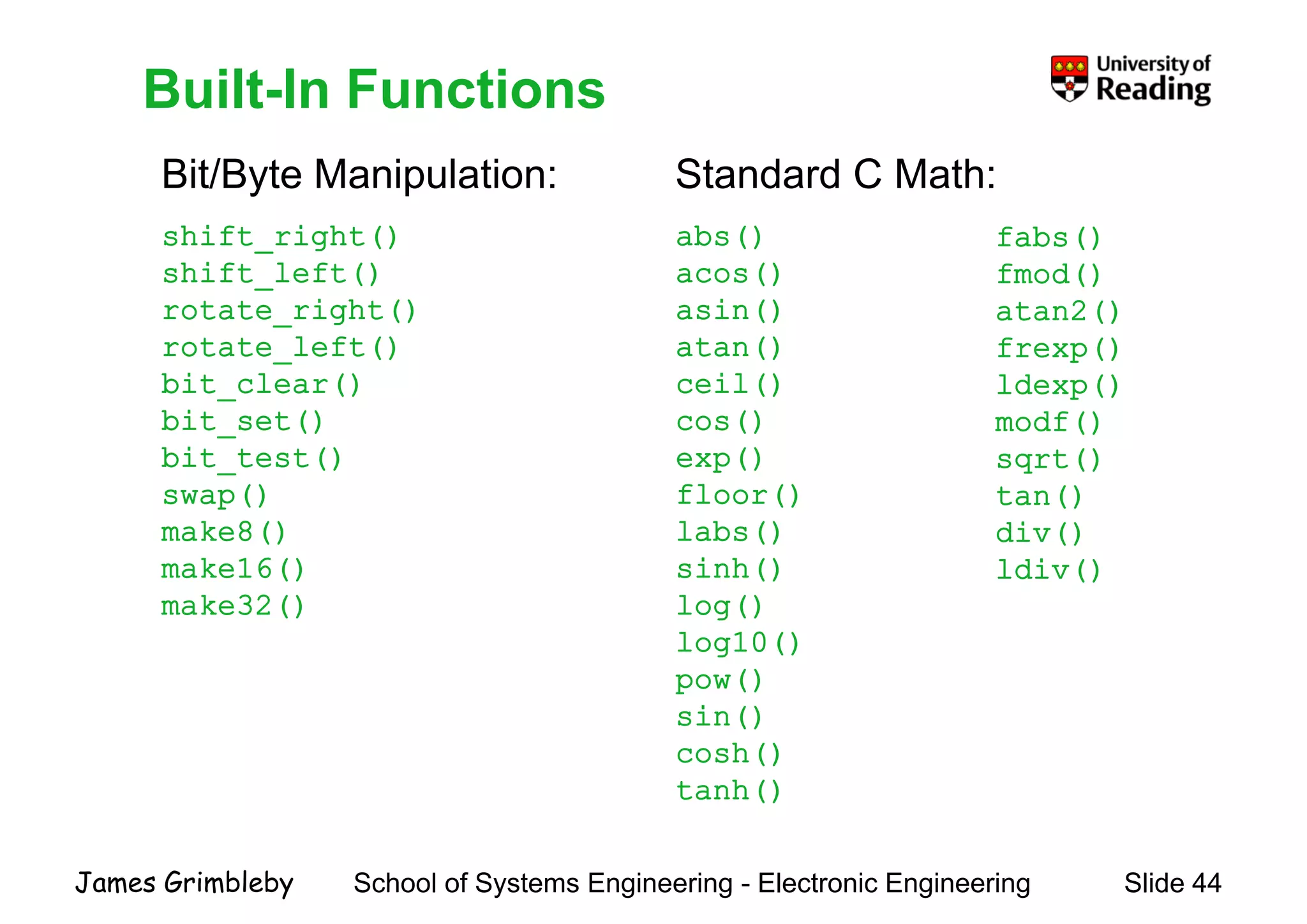
    Built-In Functions Bit/Byte Manipulation:Standard C Math: Built In Functions shift_right() shift_left() rotate right() abs() acos() asin() fabs() fmod() atan2()rotate_right() rotate_left() bit_clear() bit t() asin() atan() ceil() () atan2() frexp() ldexp() df()bit_set() bit_test() swap() cos() exp() floor() modf() sqrt() tan() make8() make16() make32() labs() sinh() log() div() ldiv() () g() log10() pow() sin()sin() cosh() tanh() School of Systems Engineering - Electronic Engineering Slide 44James Grimbleby
  • 45.
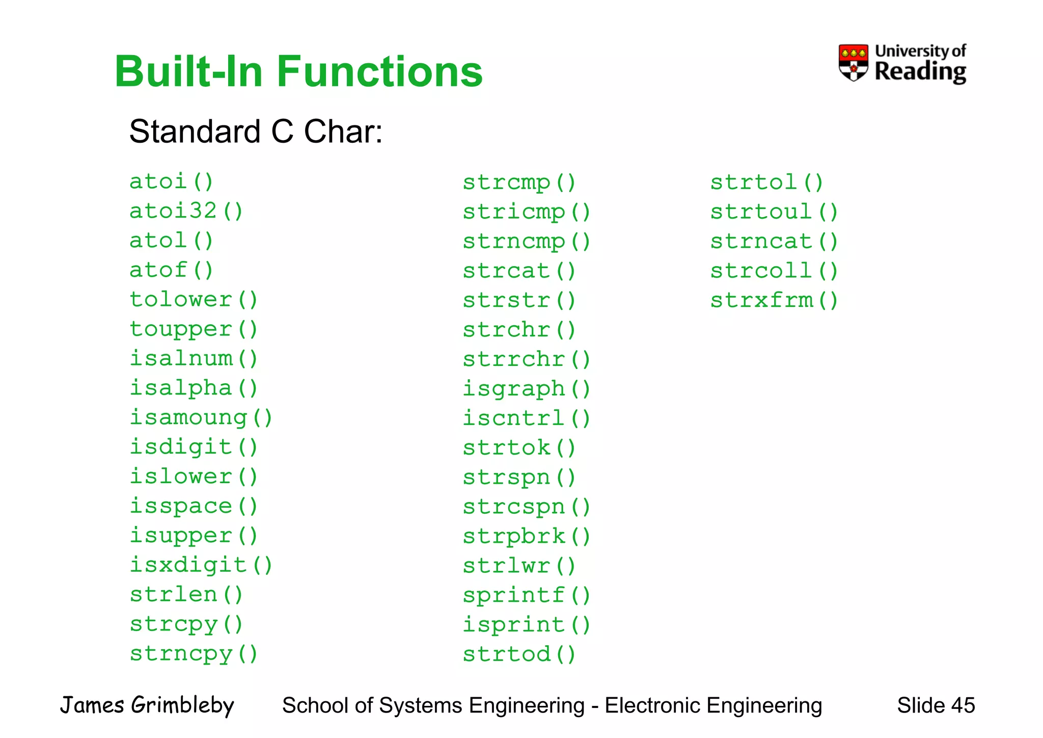
    Built-In Functions Standard CChar: Built In Functions atoi() atoi32() atol() strcmp() stricmp() strncmp() strtol() strtoul() strncat()atol() atof() tolower() toupper() strncmp() strcat() strstr() strchr() strncat() strcoll() strxfrm() toupper() isalnum() isalpha() i () strchr() strrchr() isgraph() i t l()isamoung() isdigit() islower() iscntrl() strtok() strspn() isspace() isupper() isxdigit() strcspn() strpbrk() strlwr()g () strlen() strcpy() strncpy() () sprintf() isprint() strtod() School of Systems Engineering - Electronic Engineering Slide 45James Grimbleby strncpy() strtod()
  • 46.
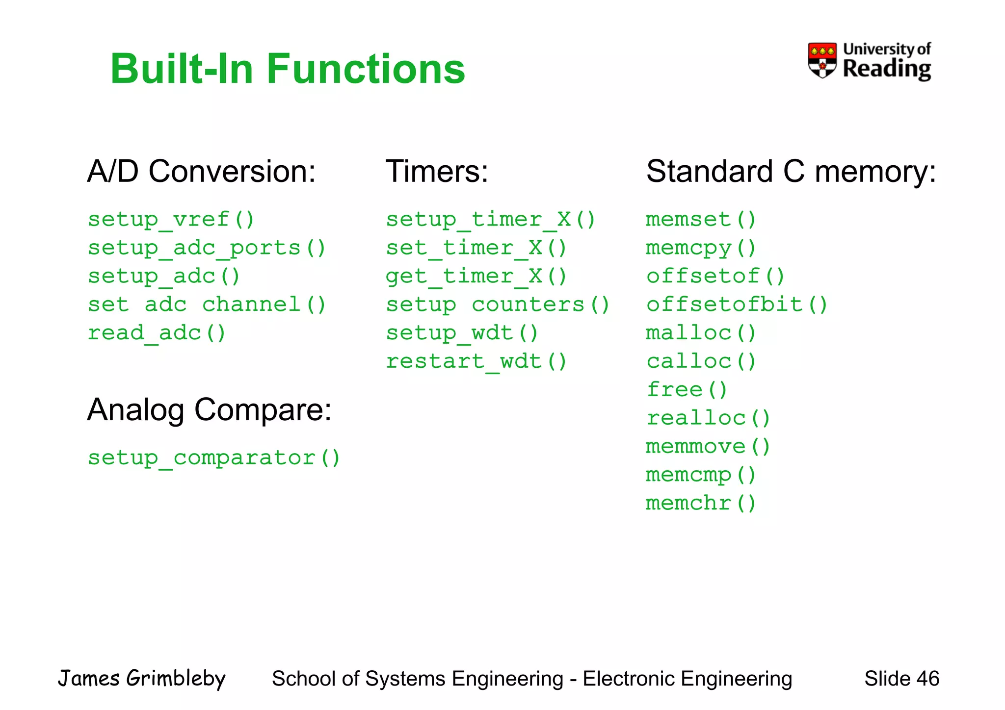
    Built-In FunctionsBuilt InFunctions A/D Conversion: setup_vref() d () Timers: setup_timer_X() i () Standard C memory: memset() ()setup_adc_ports() setup_adc() set_adc_channel() set_timer_X() get_timer_X() setup_counters() memcpy() offsetof() offsetofbit() read_adc() p setup_wdt() restart_wdt() malloc() calloc() free()free() realloc() memmove() memcmp() Analog Compare: setup_comparator() memcmp() memchr() School of Systems Engineering - Electronic Engineering Slide 46James Grimbleby
  • 47.
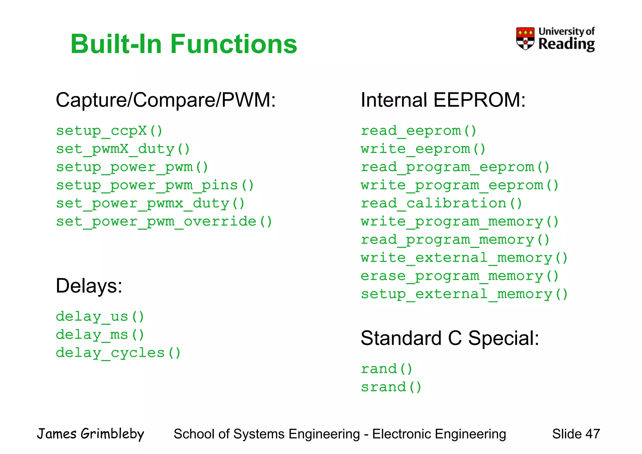
    Built-In Functions Capture/Compare/PWM: InternalEEPROM: Built In Functions Capture/Compare/PWM: setup_ccpX() set pwmX duty() Internal EEPROM: read_eeprom() write eeprom()set_pwmX_duty() setup_power_pwm() setup_power_pwm_pins() set power pwmx duty() write_eeprom() read_program_eeprom() write_program_eeprom() read calibration()set_power_pwmx_duty() set_power_pwm_override() read_calibration() write_program_memory() read_program_memory() i l ()write_external_memory() erase_program_memory() setup_external_memory()Delays: Standard C Special: delay_us() delay_ms() delay cycles() rand() srand() delay_cycles() School of Systems Engineering - Electronic Engineering Slide 47James Grimbleby
  • 48.
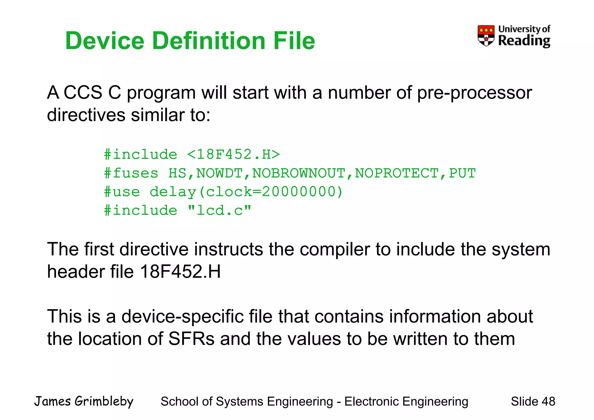
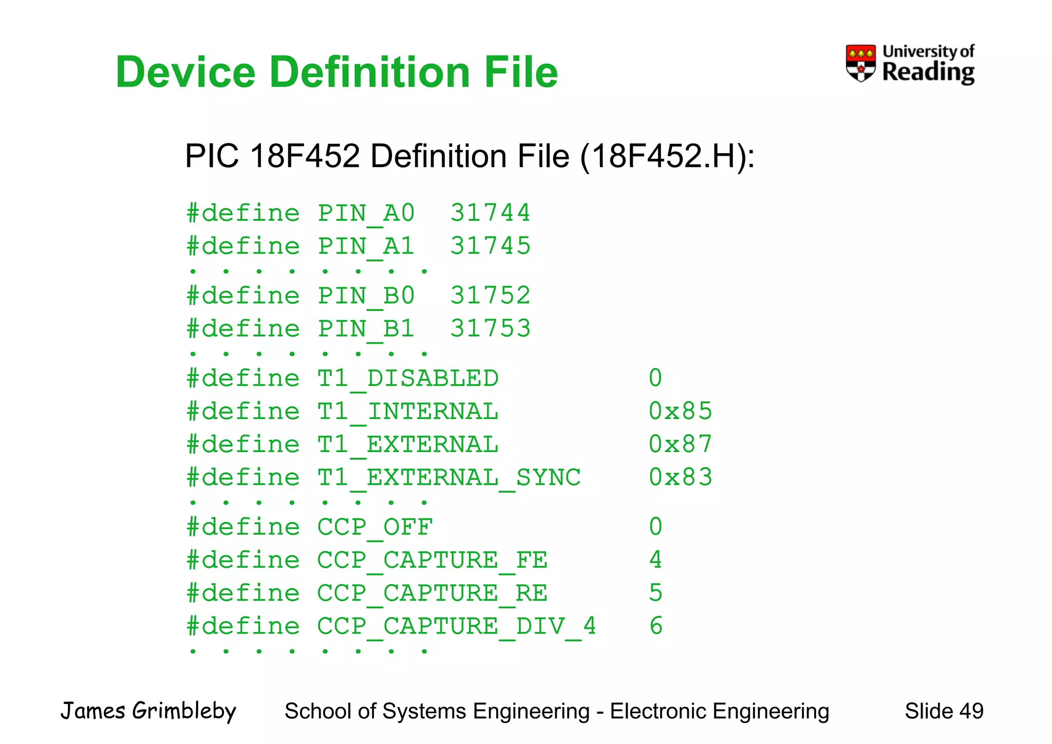
    Device Definition File ACCS C program will start with a number of pre-processor Device Definition File A CCS C program will start with a number of pre-processor directives similar to: #include <18F452.H> #fuses HS,NOWDT,NOBROWNOUT,NOPROTECT,PUT # d l ( l k 20000000)#use delay(clock=20000000) #include "lcd.c" The first directive instructs the compiler to include the system header file 18F452.H This is a device-specific file that contains information about the location of SFRs and the values to be written to them School of Systems Engineering - Electronic Engineering Slide 48James Grimbleby
  • 49.
    Device Definition File PIC18F452 Definition File (18F452.H): Device Definition File PIC 18F452 Definition File (18F452.H): #define PIN_A0 31744 #define PIN A1 31745#define PIN_A1 31745 . . . . . . . . #define PIN_B0 31752 #define PIN B1 31753#define PIN_B1 31753 . . . . . . . . #define T1_DISABLED 0 #define T1 INTERNAL 0x85#define T1_INTERNAL 0x85 #define T1_EXTERNAL 0x87 #define T1_EXTERNAL_SYNC 0x83 . . . . . . . . #define CCP_OFF 0 #define CCP_CAPTURE_FE 4 #define CCP_CAPTURE_RE 5 #define CCP_CAPTURE_DIV_4 6 . . . . . . . . School of Systems Engineering - Electronic Engineering Slide 49James Grimbleby
  • 50.
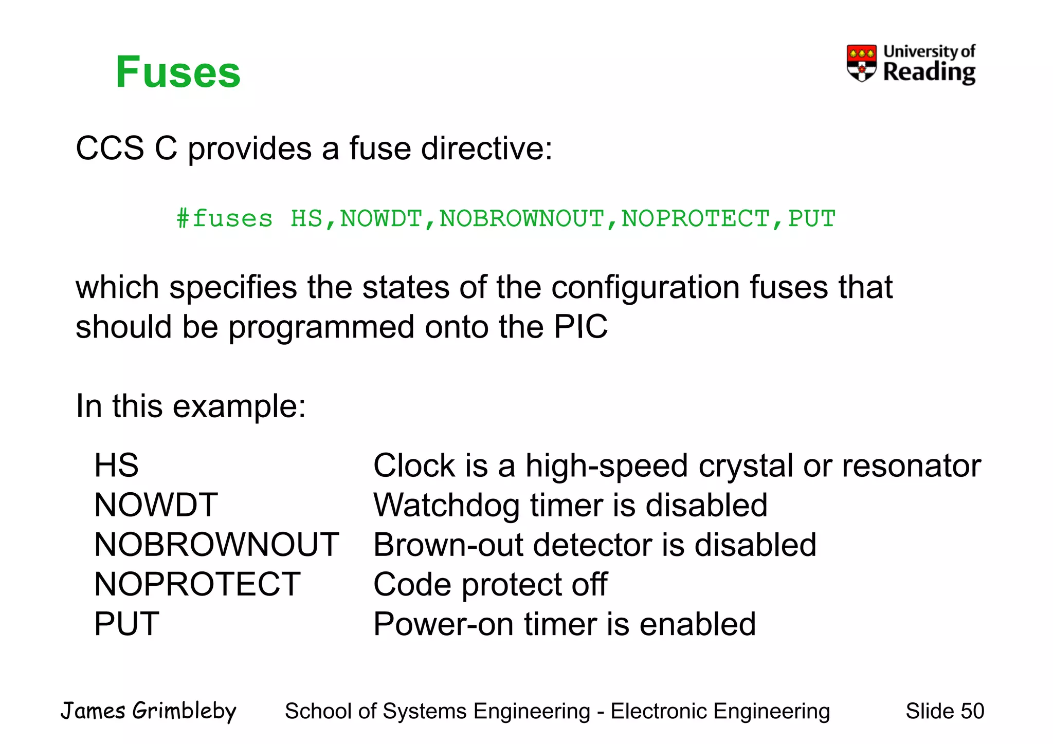
    Fuses CCS C providesa fuse directive: Fuses p #fuses HS,NOWDT,NOBROWNOUT,NOPROTECT,PUT which specifies the states of the configuration fuses that should be programmed onto the PICshould be programmed onto the PIC In this example:In this example: HS Clock is a high-speed crystal or resonator NOWDT W t hd ti i di bl dNOWDT Watchdog timer is disabled NOBROWNOUT Brown-out detector is disabled NOPROTECT Code protect offNOPROTECT Code protect off PUT Power-on timer is enabled School of Systems Engineering - Electronic Engineering Slide 50James Grimbleby
  • 51.
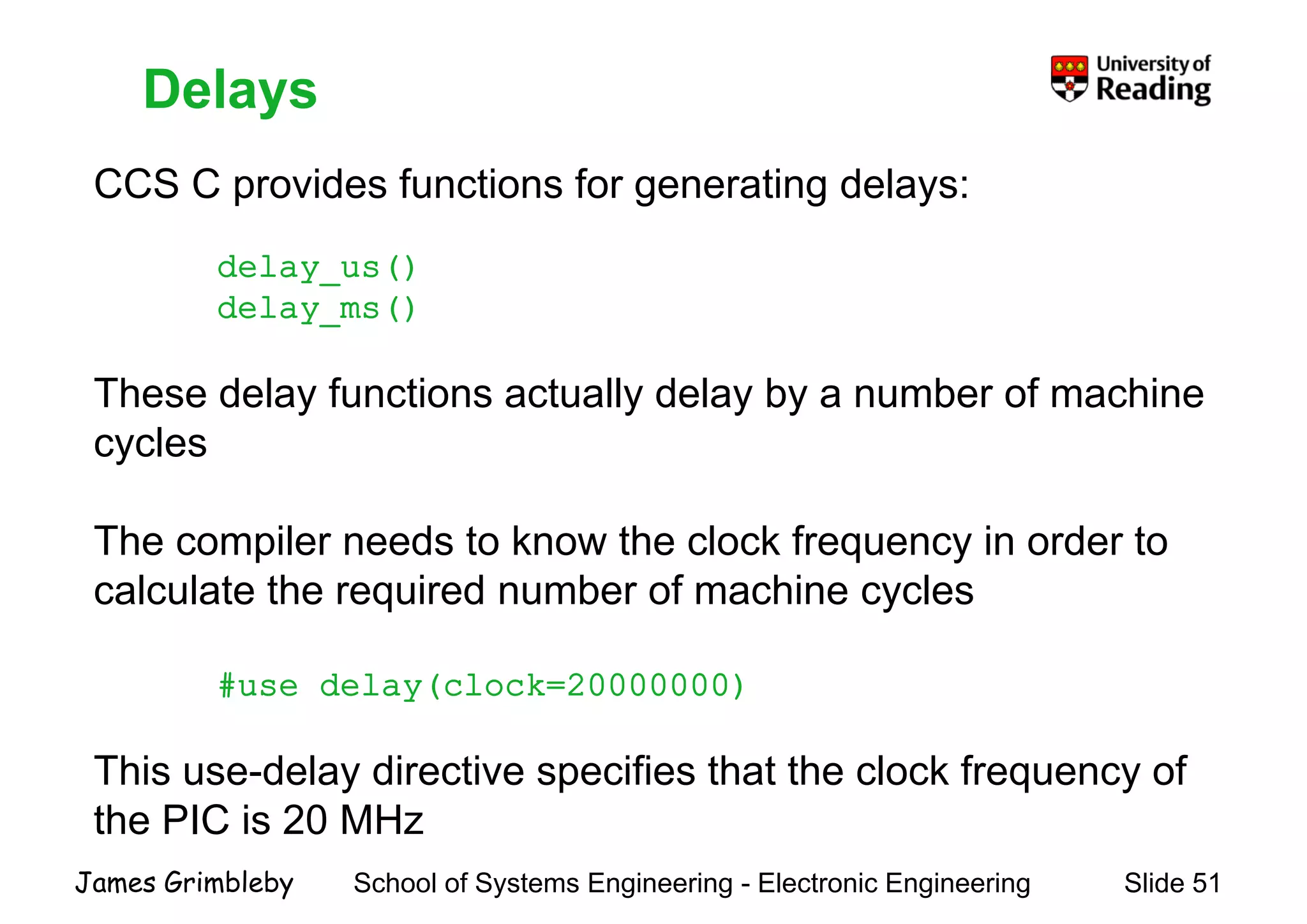
    Delays CCS C providesfunctions for generating delays: Delays p g g y delay_us() delay ms()delay_ms() These delay functions actually delay by a number of machiney y y y cycles The compiler needs to know the clock frequency in order to calculate the required number of machine cycles #use delay(clock=20000000) This use-delay directive specifies that the clock frequency of the PIC is 20 MHz School of Systems Engineering - Electronic Engineering Slide 51James Grimbleby the PIC is 20 MHz
  • 52.
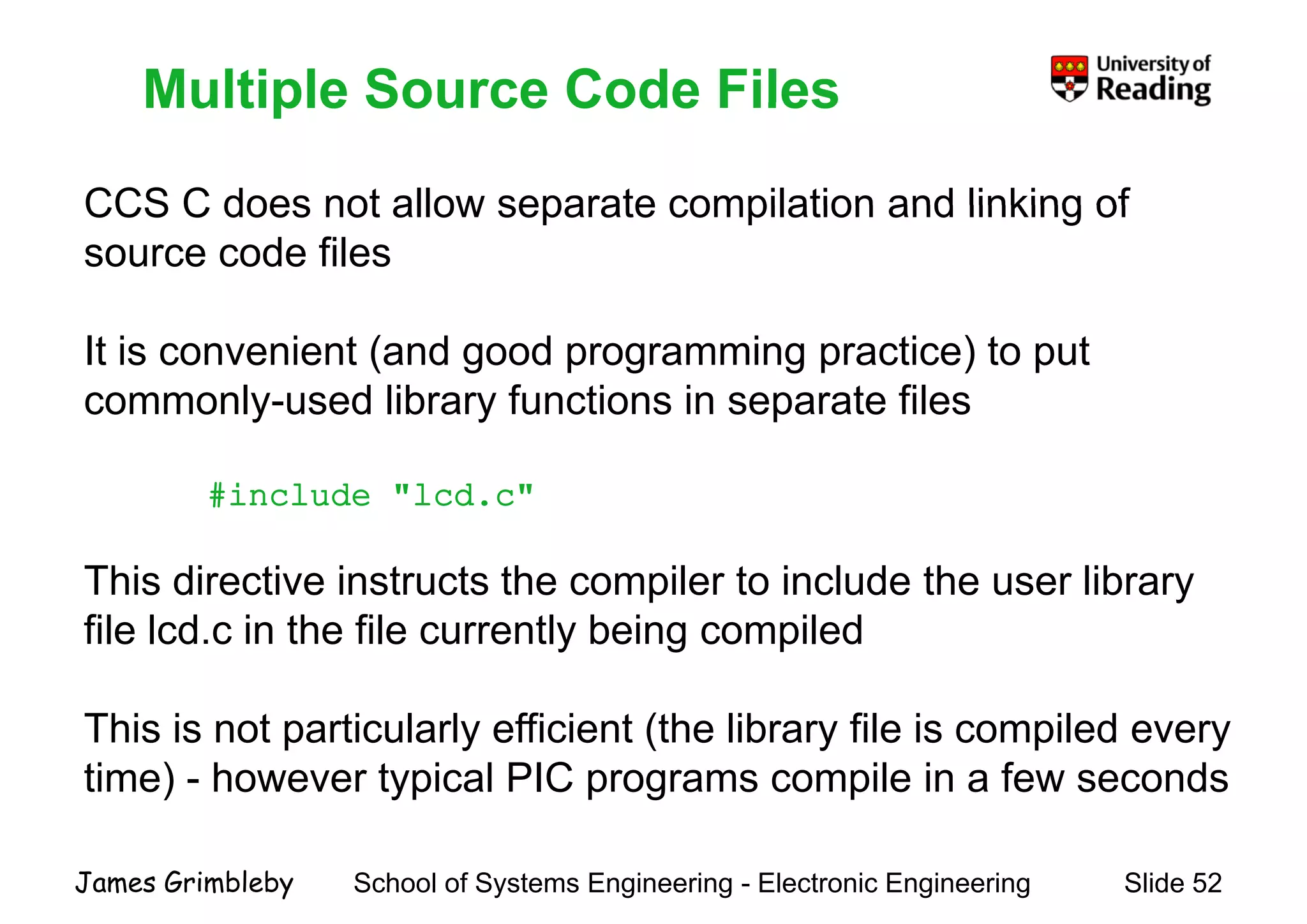
    Multiple Source CodeFiles CCS C does not allow separate compilation and linking of Multiple Source Code Files CCS C does not allow separate compilation and linking of source code files It is convenient (and good programming practice) to put commonly-used library functions in separate filescommonly used library functions in separate files #include "lcd.c" This directive instructs the compiler to include the user library fil l d i th fil tl b i il dfile lcd.c in the file currently being compiled Thi i t ti l l ffi i t (th lib fil i il dThis is not particularly efficient (the library file is compiled every time) - however typical PIC programs compile in a few seconds School of Systems Engineering - Electronic Engineering Slide 52James Grimbleby
  • 53.
    Programming PIC MicrocontrollersProgrammingPIC Microcontrollers Lecture 3 Data PortsData Ports School of Systems Engineering - Electronic Engineering Slide 53James Grimbleby
  • 54.
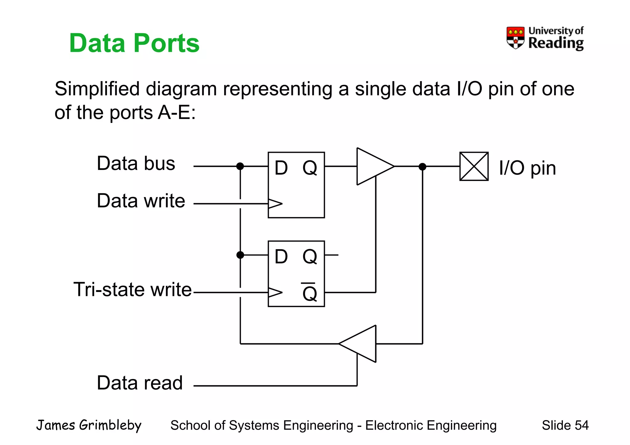
    Data Ports Simplified diagramrepresenting a single data I/O pin of one Data Ports p g p g g p of the ports A-E: D QData bus Data write I/O pin Data write D Q Q Tri-state write Qs a e e Data read School of Systems Engineering - Electronic Engineering Slide 54James Grimbleby
  • 55.
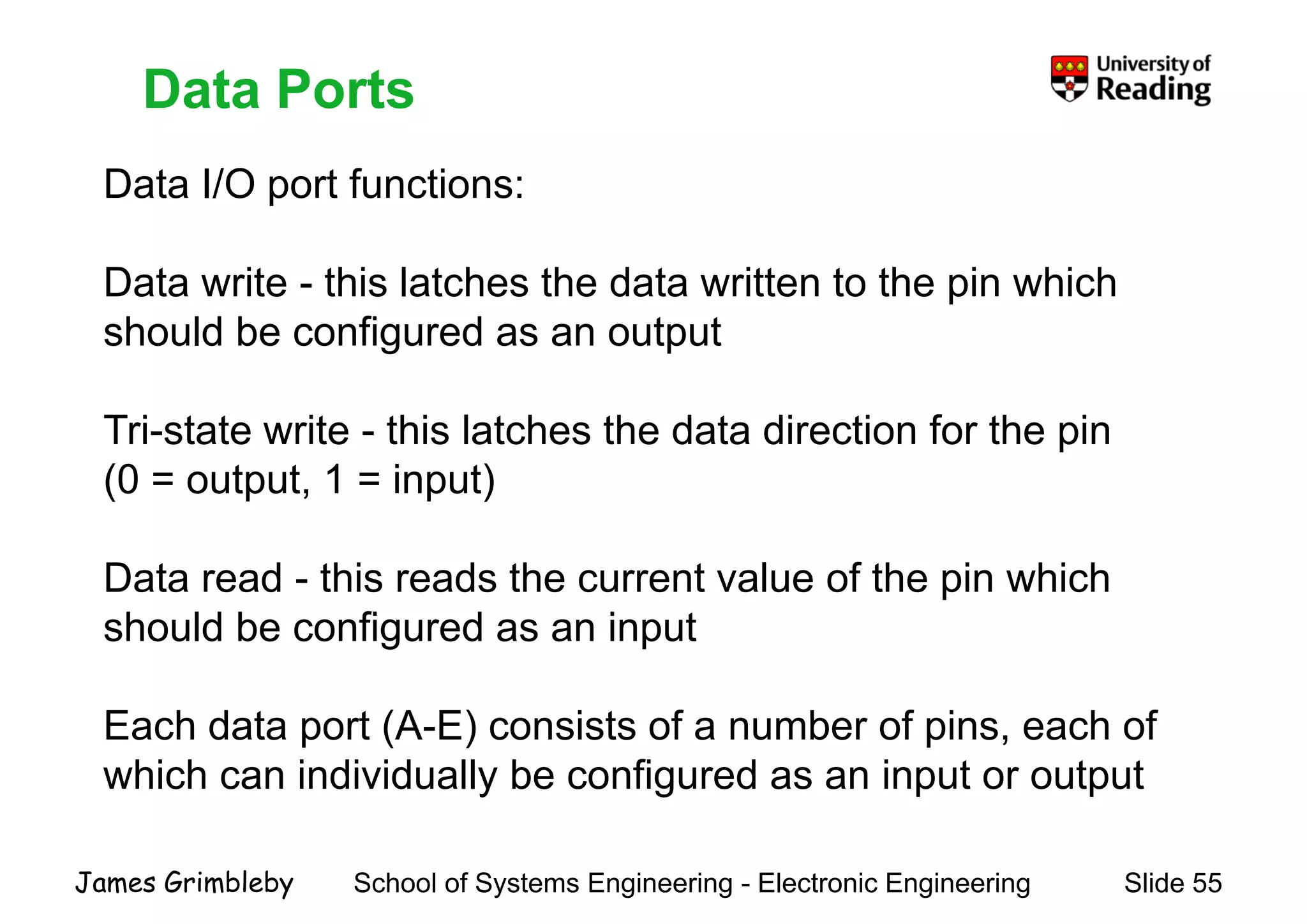
    Data Ports Data I/Oport functions: Data Ports p Data write - this latches the data written to the pin which should be configured as an output Tri-state write - this latches the data direction for the pin (0 = output, 1 = input) Data read - this reads the current value of the pin which h ld b fi d i tshould be configured as an input Each data port (A E) consists of a n mber of pins each ofEach data port (A-E) consists of a number of pins, each of which can individually be configured as an input or output School of Systems Engineering - Electronic Engineering Slide 55James Grimbleby
  • 56.
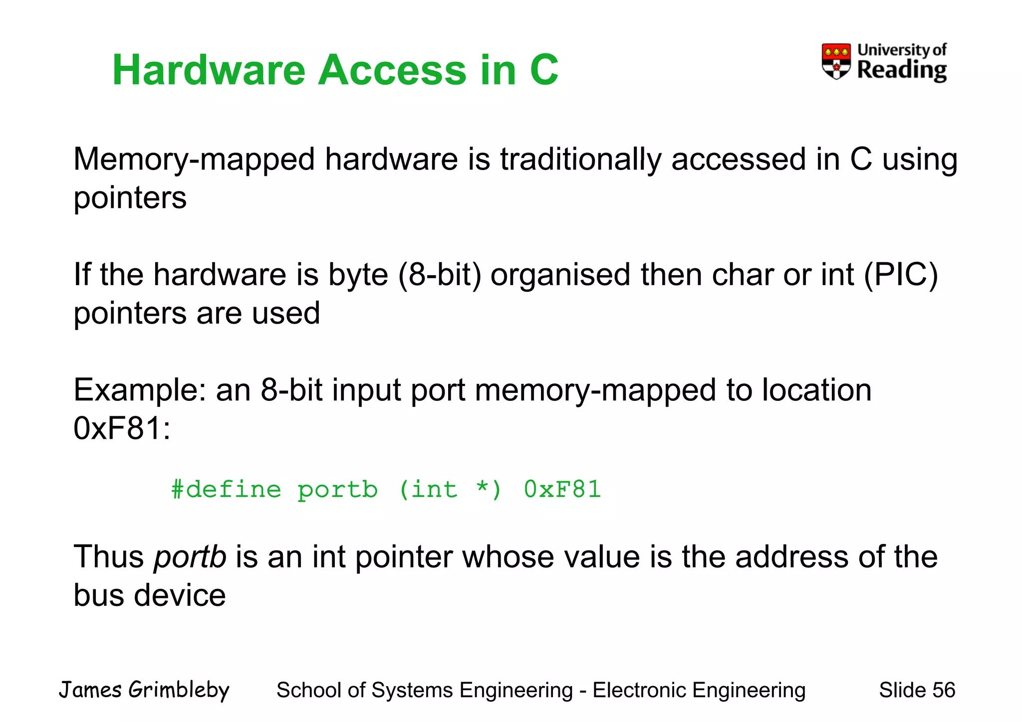
    Hardware Access inC Memory-mapped hardware is traditionally accessed in C using Hardware Access in C Memory-mapped hardware is traditionally accessed in C using pointers If the hardware is byte (8-bit) organised then char or int (PIC) pointers are usedpointers are used Example: an 8-bit input port memory-mapped to locationa p e a 8 b t put po t e o y apped to ocat o 0xF81: #d fi tb (i t *) 0 F81#define portb (int *) 0xF81 Thus portb is an int pointer whose value is the address of theThus portb is an int pointer whose value is the address of the bus device School of Systems Engineering - Electronic Engineering Slide 56James Grimbleby
  • 57.
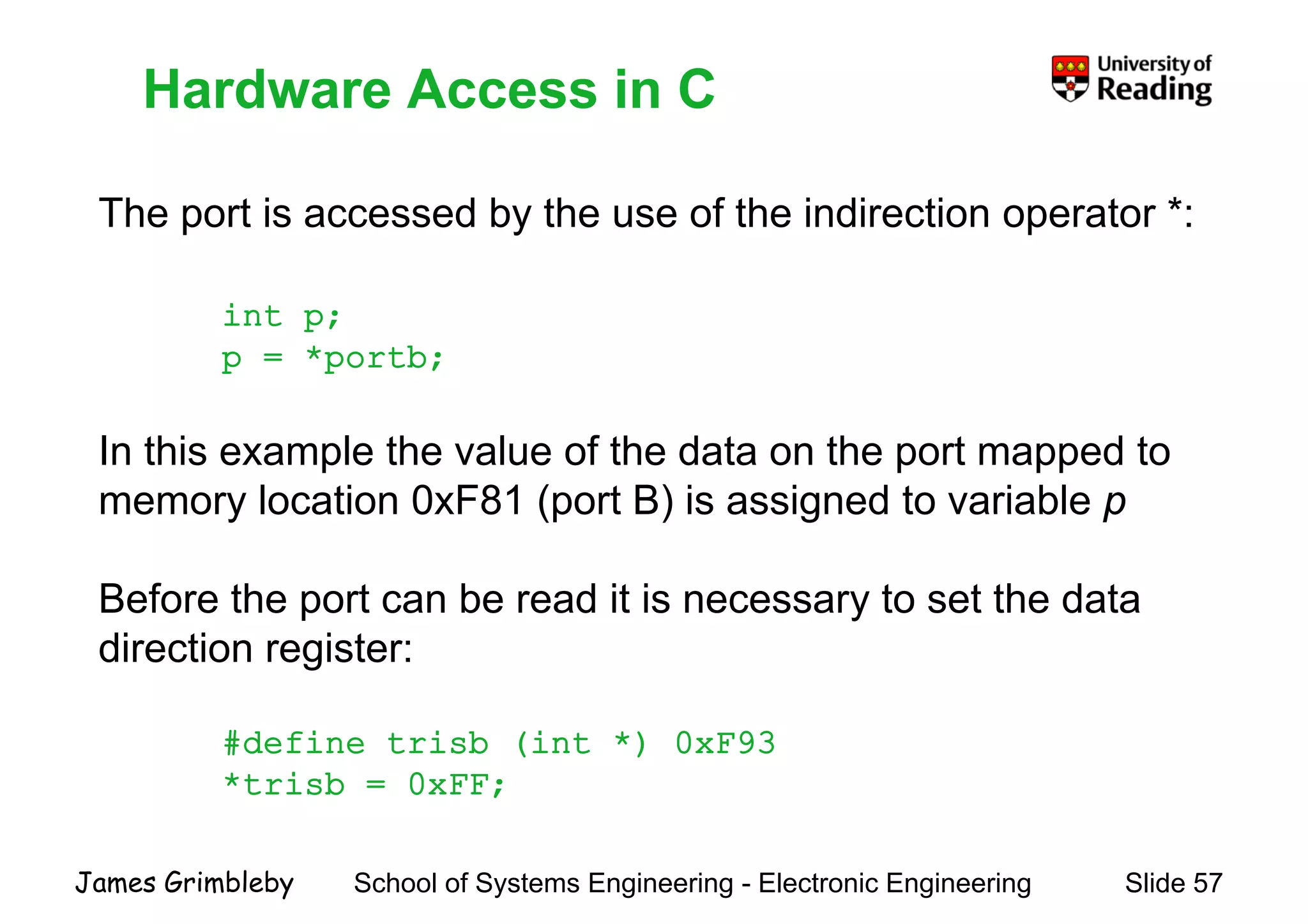
    Hardware Access inC Th t i d b th f th i di ti t * Hardware Access in C The port is accessed by the use of the indirection operator *: int p;int p; p = *portb; In this example the value of the data on the port mapped to memory location 0xF81 (port B) is assigned to variable pmemory location 0xF81 (port B) is assigned to variable p Before the port can be read it is necessary to set the datap y direction register: #define trisb (int *) 0xF93 *trisb = 0xFF; School of Systems Engineering - Electronic Engineering Slide 57James Grimbleby
  • 58.
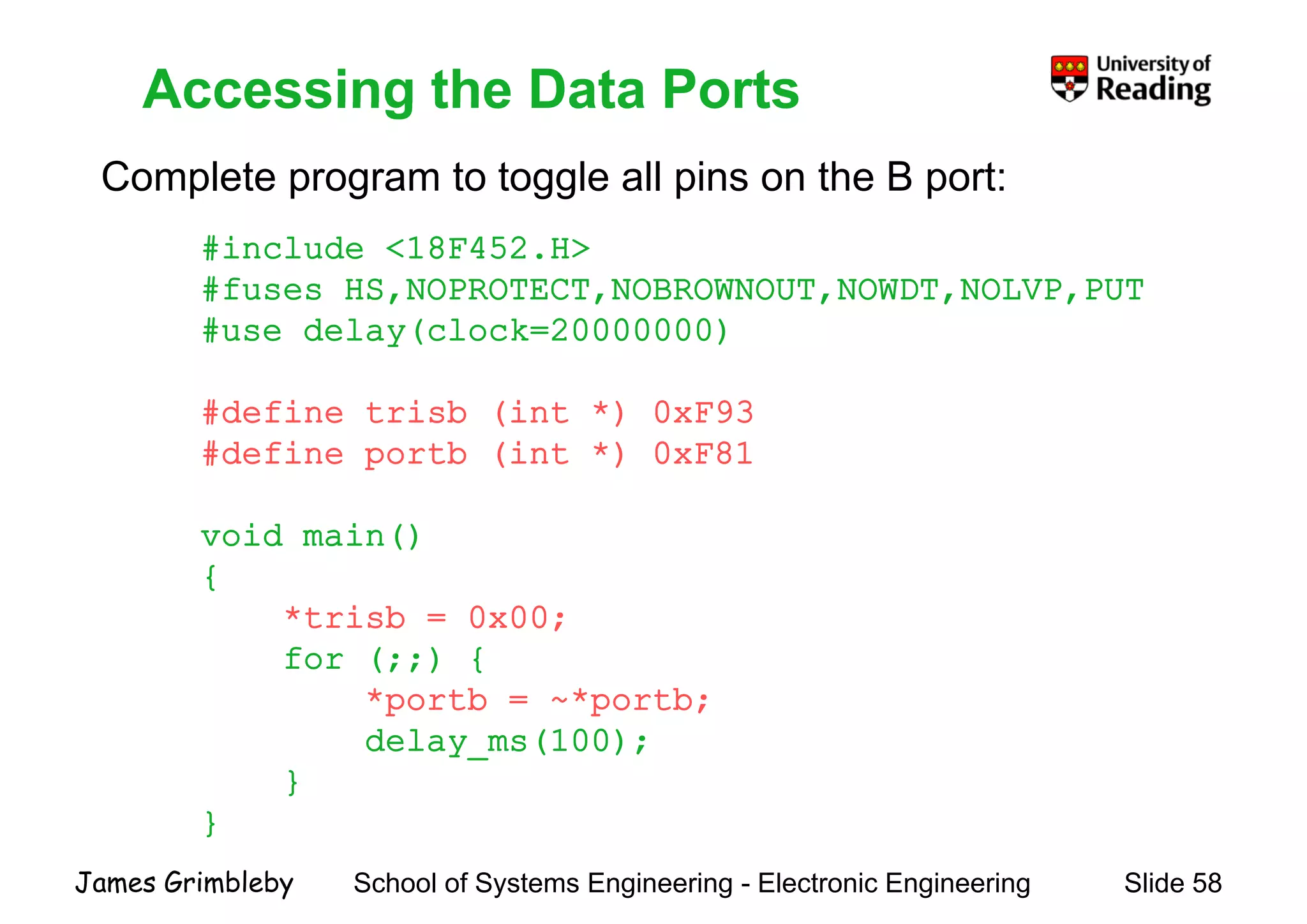
    Accessing the DataPorts Complete program to toggle all pins on the B port: Accessing the Data Ports #include <18F452.H> #fuses HS,NOPROTECT,NOBROWNOUT,NOWDT,NOLVP,PUT #use delay(clock=20000000) #define trisb (int *) 0xF93#define trisb (int *) 0xF93 #define portb (int *) 0xF81 void main() { *trisb = 0x00;*trisb = 0x00; for (;;) { *portb = ~*portb; delay_ms(100); } } School of Systems Engineering - Electronic Engineering Slide 58James Grimbleby }
  • 59.
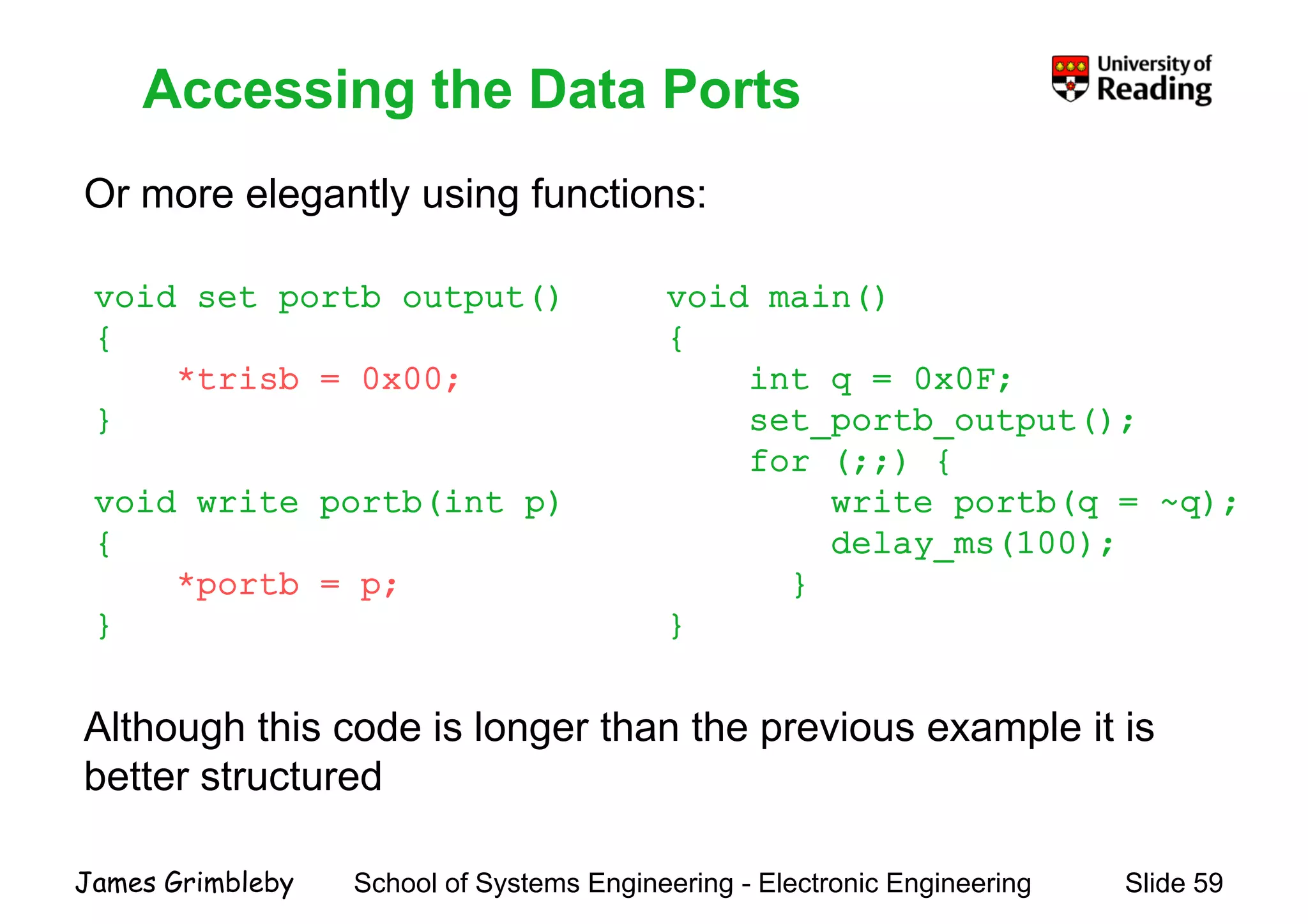
    Accessing the DataPorts Or more elegantly using functions: Accessing the Data Ports Or more elegantly using functions: void set_portb_output() void main()_p _ p () { *trisb = 0x00; } () { int q = 0x0F; t tb t t()} void write_portb(int p) set_portb_output(); for (;;) { write_portb(q = ~q);_p ( p) { *portb = p; } _p (q q); delay_ms(100); } }} } Alth h thi d i l th th i l it iAlthough this code is longer than the previous example it is better structured School of Systems Engineering - Electronic Engineering Slide 59James Grimbleby
  • 60.
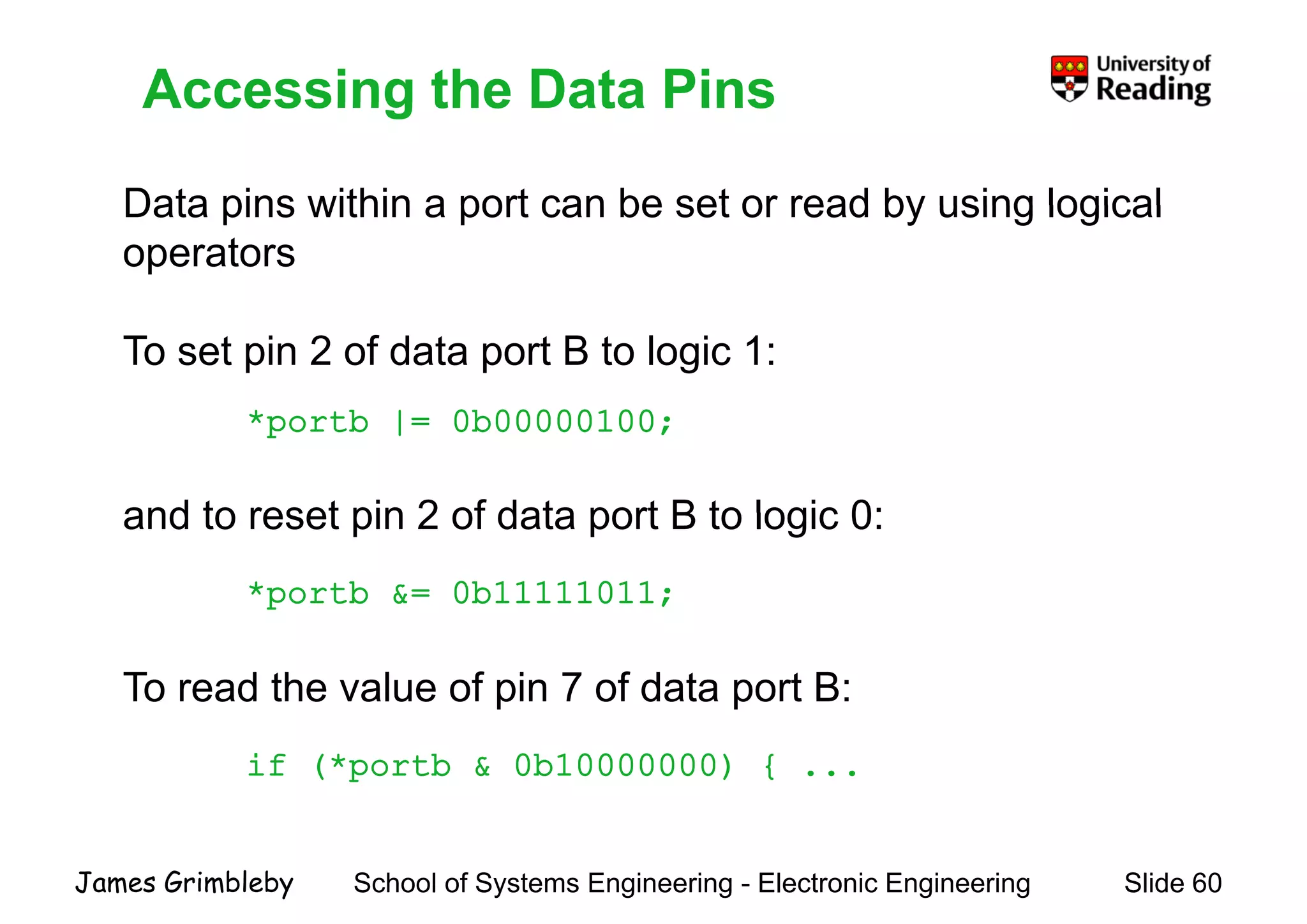
    Accessing the DataPins Data pins within a port can be set or read by using logical Accessing the Data Pins Data pins within a port can be set or read by using logical operators To set pin 2 of data port B to logic 1: * tb | 0b00000100*portb |= 0b00000100; and to reset pin 2 of data port B to logic 0:and to reset pin 2 of data port B to logic 0: *portb &= 0b11111011; To read the value of pin 7 of data port B: if (*portb & 0b10000000) { ... School of Systems Engineering - Electronic Engineering Slide 60James Grimbleby
  • 61.
    CCS C Supportfor Port I/O C h i t i id d i CCS C f i CCS C Support for Port I/O Comprehensive support is provided in CCS C for accessing data ports and individual pins of the ports Three different methods of I/O can be used, specified by the directives:directives: #use standard_io(port) #use fast_io(port) #use fixed io(port outputs=pin x1 pin x2 )#use fixed_io(port_outputs=pin_x1,pin_x2, ...) The differences between these I/O methods are to do with theThe differences between these I/O methods are to do with the way that the data direction registers are controlled School of Systems Engineering - Electronic Engineering Slide 61James Grimbleby
  • 62.
    Standard I/O #use standardio(port) affects how the compiler will generate Standard I/O #use standard_io(port) affects how the compiler will generate code for input and output instructions that follow This directive takes effect until another #use xxx_io directive is encounteredis encountered The standard method of I/O will cause the compiler toe sta da d et od o /O cause t e co p e to generate code to set the direction register for each I/O operationp Standard_io is the default I/O method for all ports. Examples: #use standard_io(A) School of Systems Engineering - Electronic Engineering Slide 62James Grimbleby
  • 63.
    Fast I/O #use fastio(port) affects how the compiler will generate code Fast I/O #use fast_io(port) affects how the compiler will generate code for input and output instructions that follow This directive takes effect until another #use xxxx_io directive is encounteredis encountered The fast method of doing I/O will cause the compiler toe ast et od o do g /O cause t e co p e to perform I/O without programming of the direction register The user must ensure the direction register is set correctly via set_tris_X() . Example: #use fast_io(A) School of Systems Engineering - Electronic Engineering Slide 63James Grimbleby
  • 64.
    Fixed I/O #use fixedio(port) affects how the compiler will generate code Fixed I/O #use fixed_io(port) affects how the compiler will generate code for input and output instructions that follow This directive takes effect until another #use xxx_io directive is encountered The fixed method of I/O will cause the compiler to generate code to set the direction register for each I/O operation The pins are programmed according to the information in this directive (not the operations actually performed) Examples: #use fixed_io(a_outputs=PIN_A2,PIN_A3) School of Systems Engineering - Electronic Engineering Slide 64James Grimbleby
  • 65.
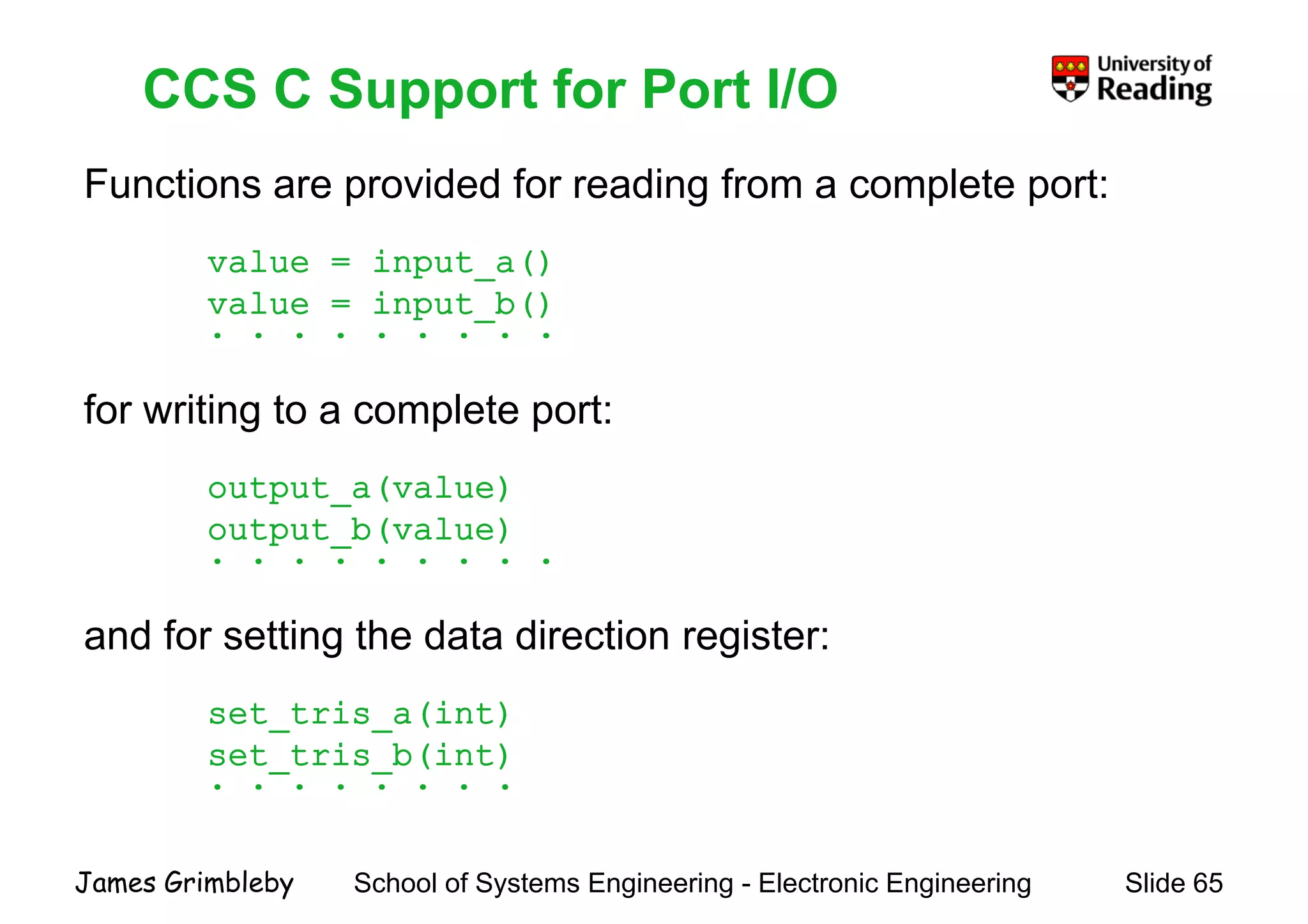
    CCS C Supportfor Port I/O Functions are provided for reading from a complete port: CCS C Support for Port I/O p g p p value = input_a() value = input b()value = input_b() . . . . . . . . . for writing to a complete port:for writing to a complete port: output_a(value) output_b(value) . . . . . . . . . and for setting the data direction register: set tris a(int)set_tris_a(int) set_tris_b(int) . . . . . . . . School of Systems Engineering - Electronic Engineering Slide 65James Grimbleby
  • 66.
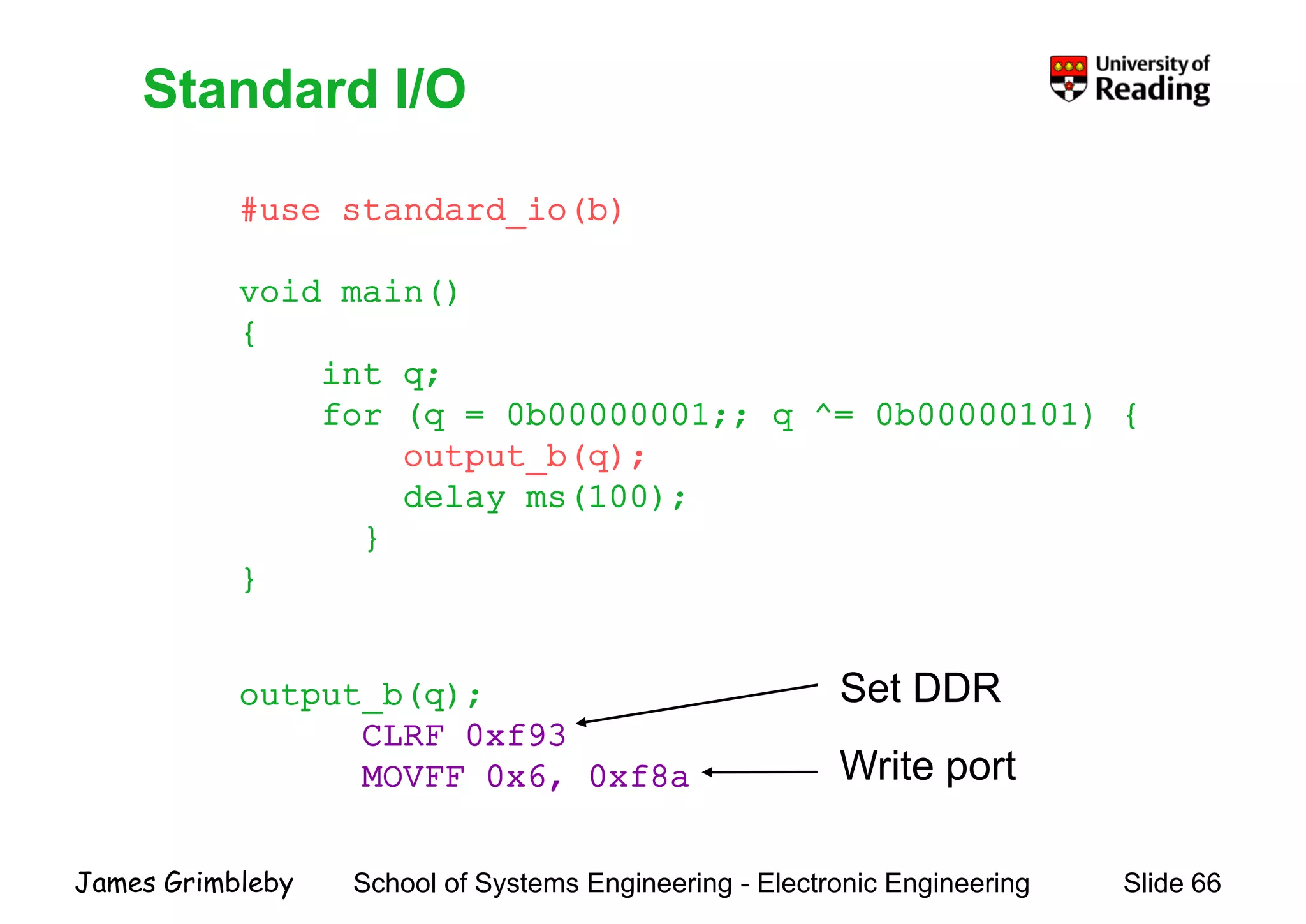
    Standard I/O #use standardio(b) Standard I/O #use standard_io(b) void main() { int q; for (q 0b00000001;; q ^ 0b00000101) {for (q = 0b00000001;; q ^= 0b00000101) { output_b(q); delay_ms(100);y } } output_b(q); Set DDR CLRF 0xf93 MOVFF 0x6, 0xf8a Write port School of Systems Engineering - Electronic Engineering Slide 66James Grimbleby
  • 67.
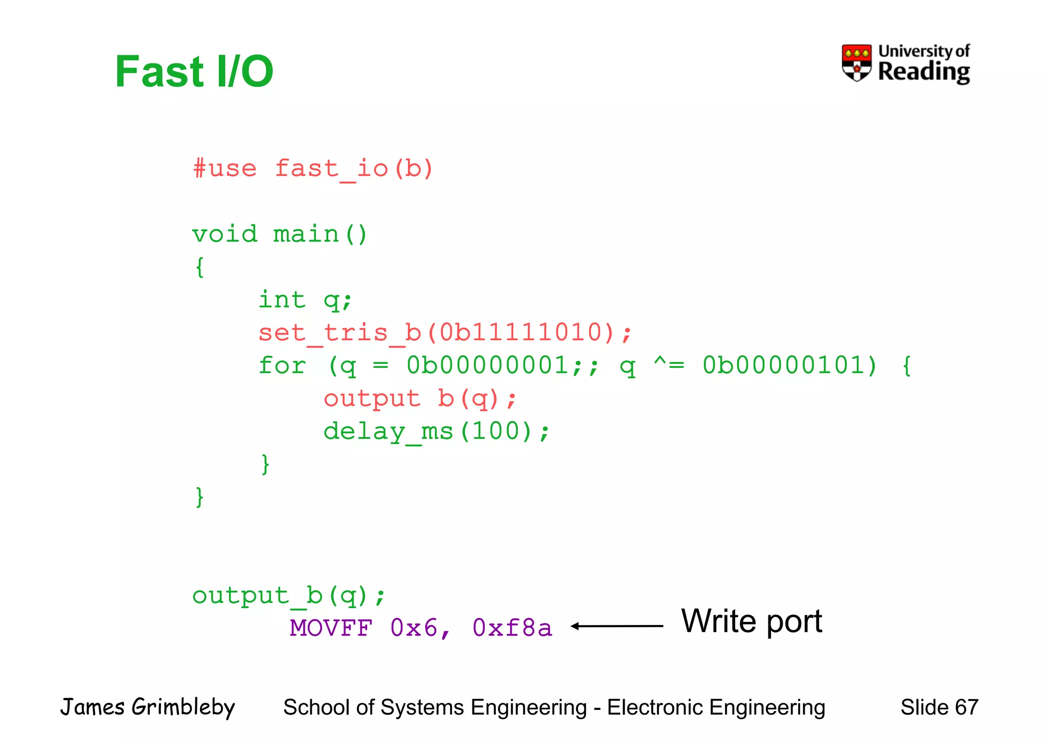
    Fast I/O #use fastio(b) Fast I/O #use fast_io(b) void main() { int q; set tris b(0b11111010);set_tris_b(0b11111010); for (q = 0b00000001;; q ^= 0b00000101) { output_b(q);p q delay_ms(100); } }} output_b(q); MOVFF 0x6, 0xf8a Write port School of Systems Engineering - Electronic Engineering Slide 67James Grimbleby
  • 68.
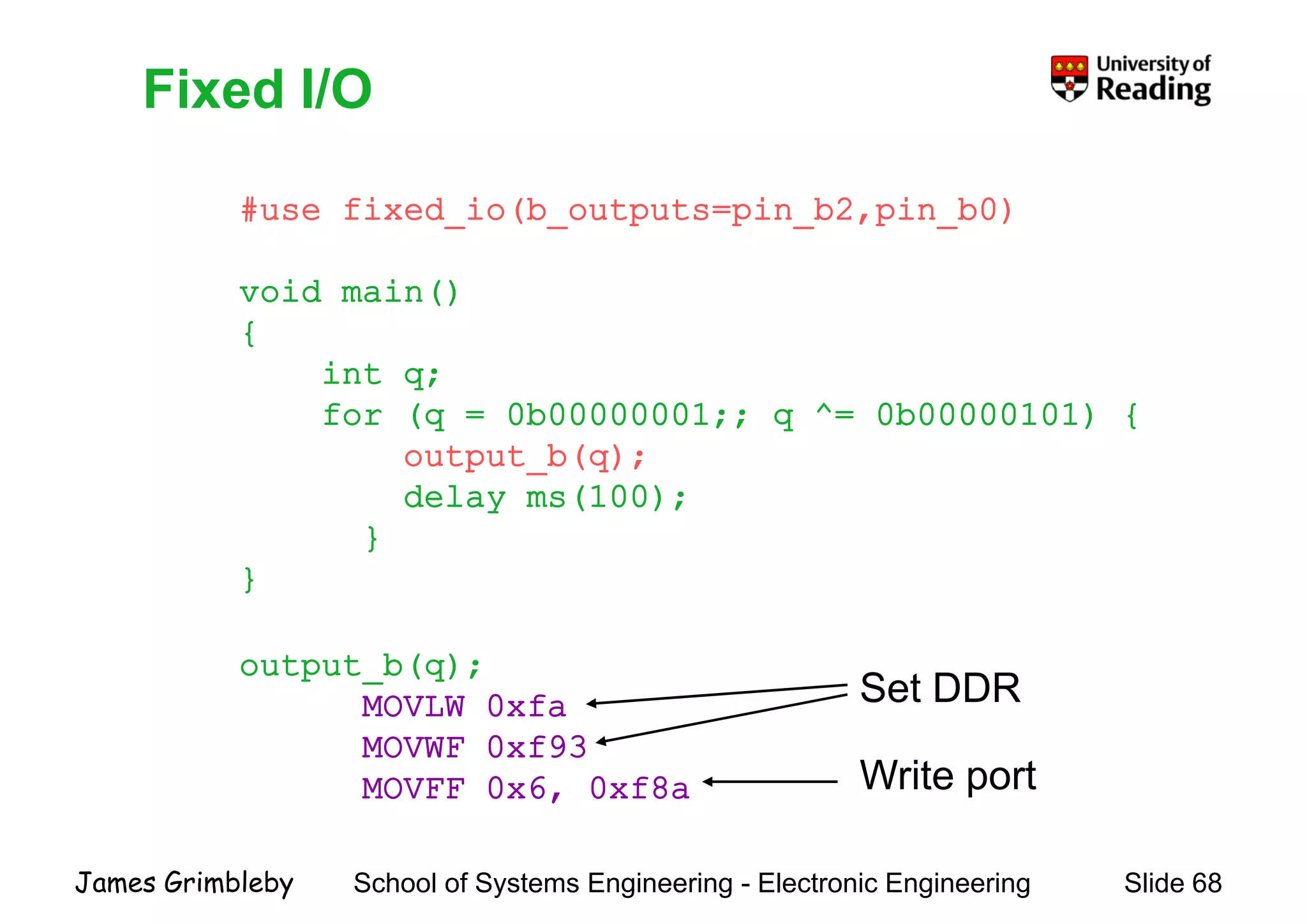
    Fixed I/O #use fixedio(b outputs pin b2 pin b0) Fixed I/O #use fixed_io(b_outputs=pin_b2,pin_b0) void main() { int q; for (q 0b00000001;; q ^ 0b00000101) {for (q = 0b00000001;; q ^= 0b00000101) { output_b(q); delay_ms(100);y } } output_b(q); MOVLW 0xfa Set DDR MOVWF 0xf93 MOVFF 0x6, 0xf8a Write port School of Systems Engineering - Electronic Engineering Slide 68James Grimbleby
  • 69.
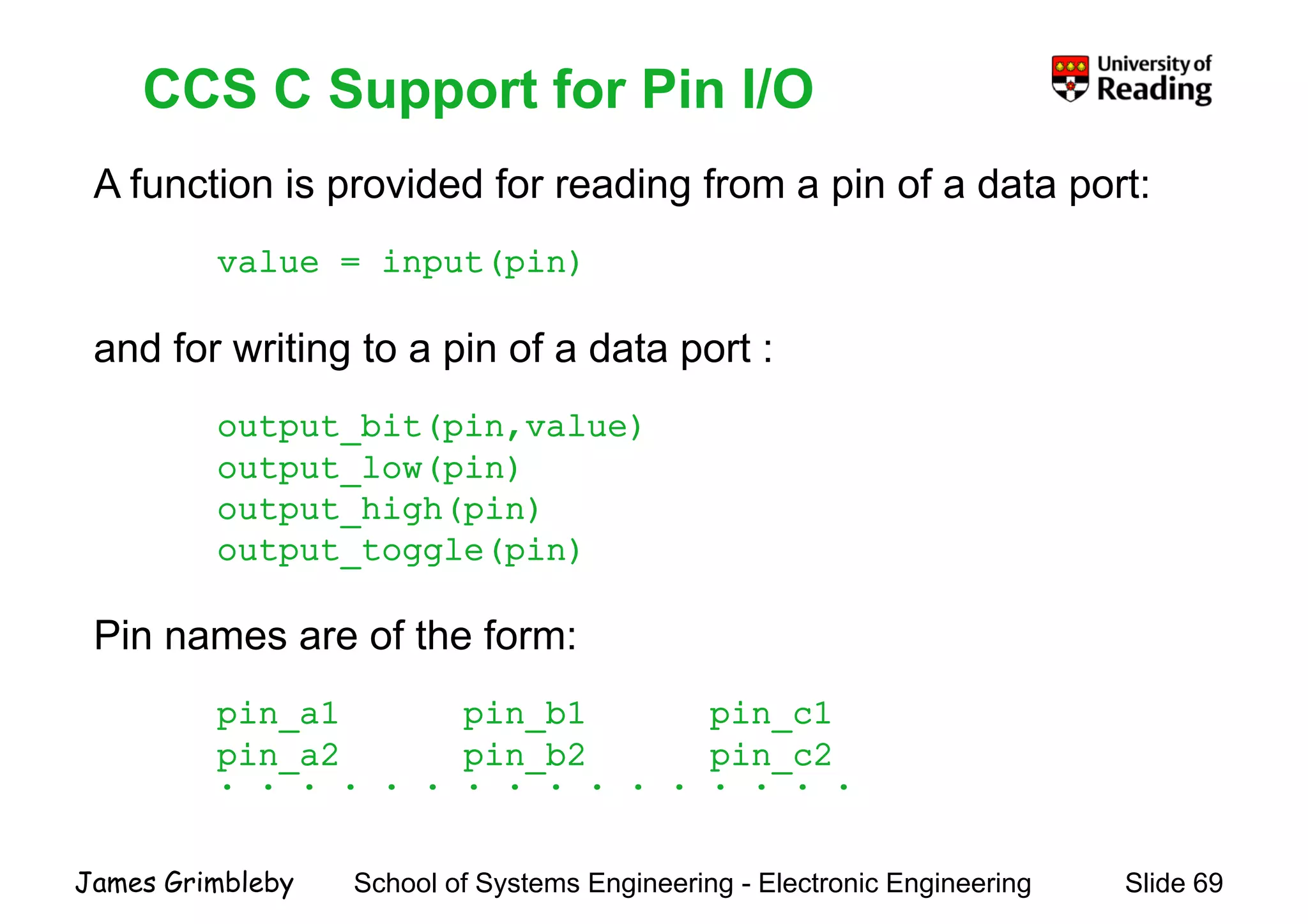
    CCS C Supportfor Pin I/O A function is provided for reading from a pin of a data port: CCS C Support for Pin I/O p g p p value = input(pin) and for writing to a pin of a data port : bi ( i l )output_bit(pin,value) output_low(pin) output high(pin)output_high(pin) output_toggle(pin) Pin names are of the form: pin a1 pin b1 pin c1pin_a1 pin_b1 pin_c1 pin_a2 pin_b2 pin_c2 . . . . . . . . . . . . . . . . School of Systems Engineering - Electronic Engineering Slide 69James Grimbleby
  • 70.
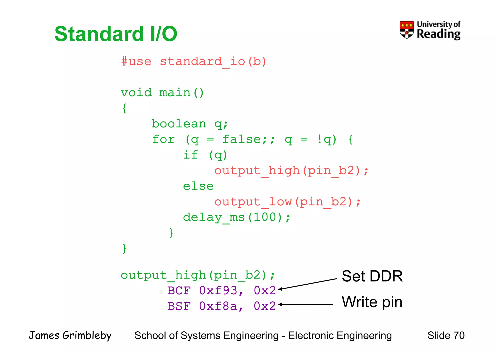
    Standard I/O #use standard_io(b) StandardI/O void main() { boolean q; for (q = false;; q = !q) { if (q)if (q) output_high(pin_b2); else output_low(pin_b2); delay_ms(100); }} } output high(pin b2); S t DDRoutput_high(pin_b2); BCF 0xf93, 0x2 BSF 0xf8a, 0x2 Set DDR Write pin School of Systems Engineering - Electronic Engineering Slide 70James Grimbleby ,
  • 71.
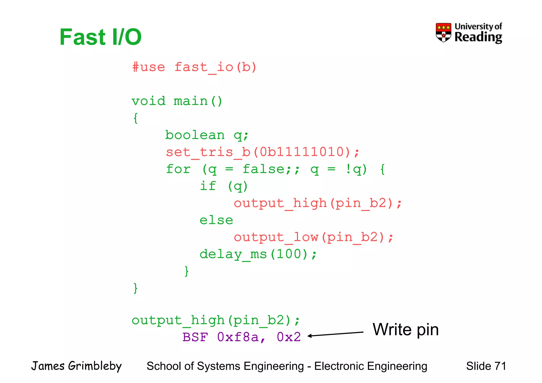
    Fast I/O #use fast_io(b) FastI/O void main() { boolean q; set_tris_b(0b11111010); for (q = false;; q = !q) {for (q = false;; q = !q) { if (q) output_high(pin_b2); else output_low(pin_b2); delay ms(100);delay_ms(100); } } output_high(pin_b2); BSF 0xf8a, 0x2 Write pin School of Systems Engineering - Electronic Engineering Slide 71James Grimbleby BSF 0xf8a, 0x2
  • 72.
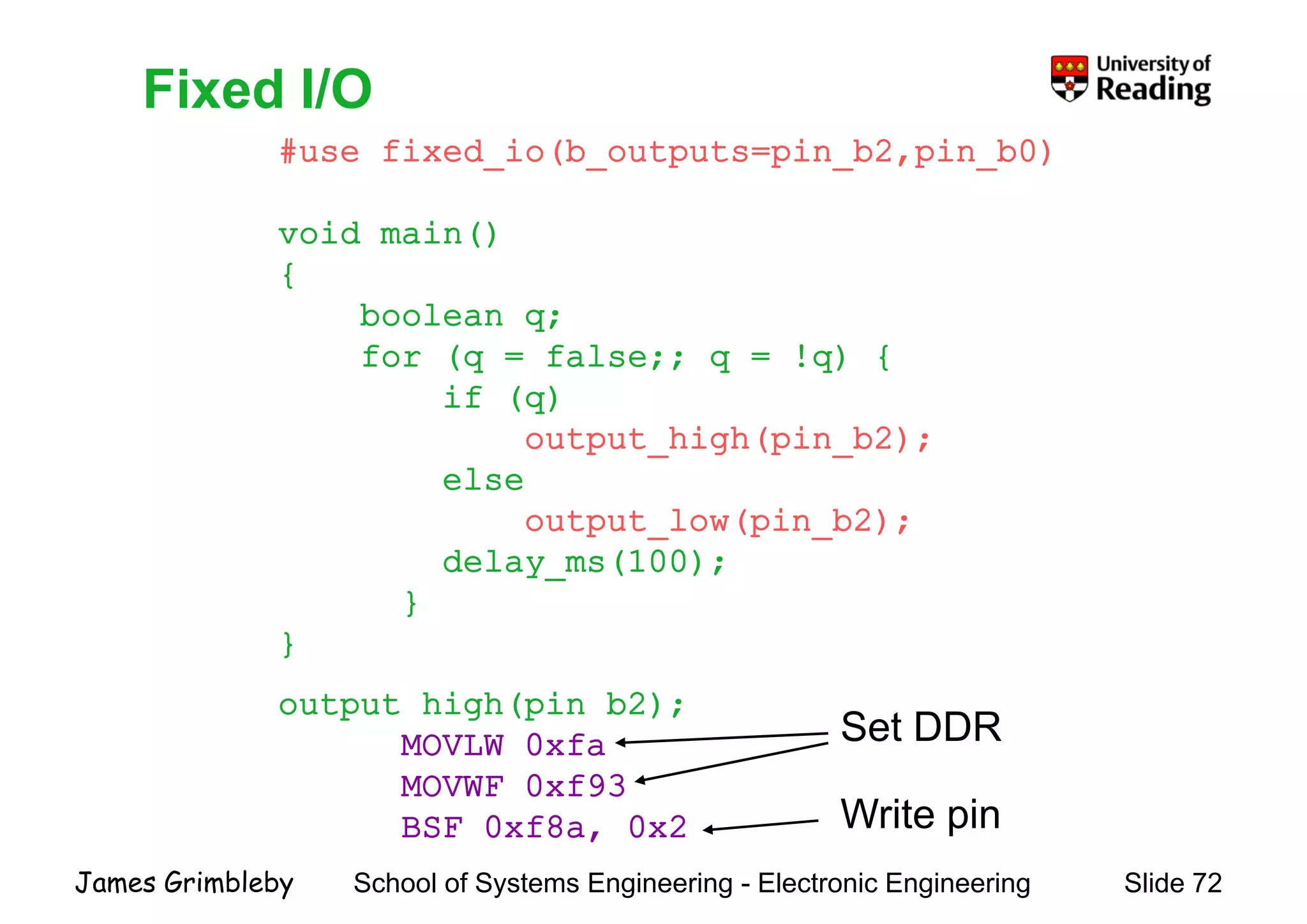
    Fixed I/O #use fixed_io(b_outputs=pin_b2,pin_b0) FixedI/O void main() { boolean q;boolean q; for (q = false;; q = !q) { if (q)(q) output_high(pin_b2); else output low(pin b2);output_low(pin_b2); delay_ms(100); }} } output_high(pin_b2); S t DDR p g (p ); MOVLW 0xfa MOVWF 0xf93 BSF 0xf8a 0x2 Set DDR Write pin School of Systems Engineering - Electronic Engineering Slide 72James Grimbleby BSF 0xf8a, 0x2 Write pin
  • 73.
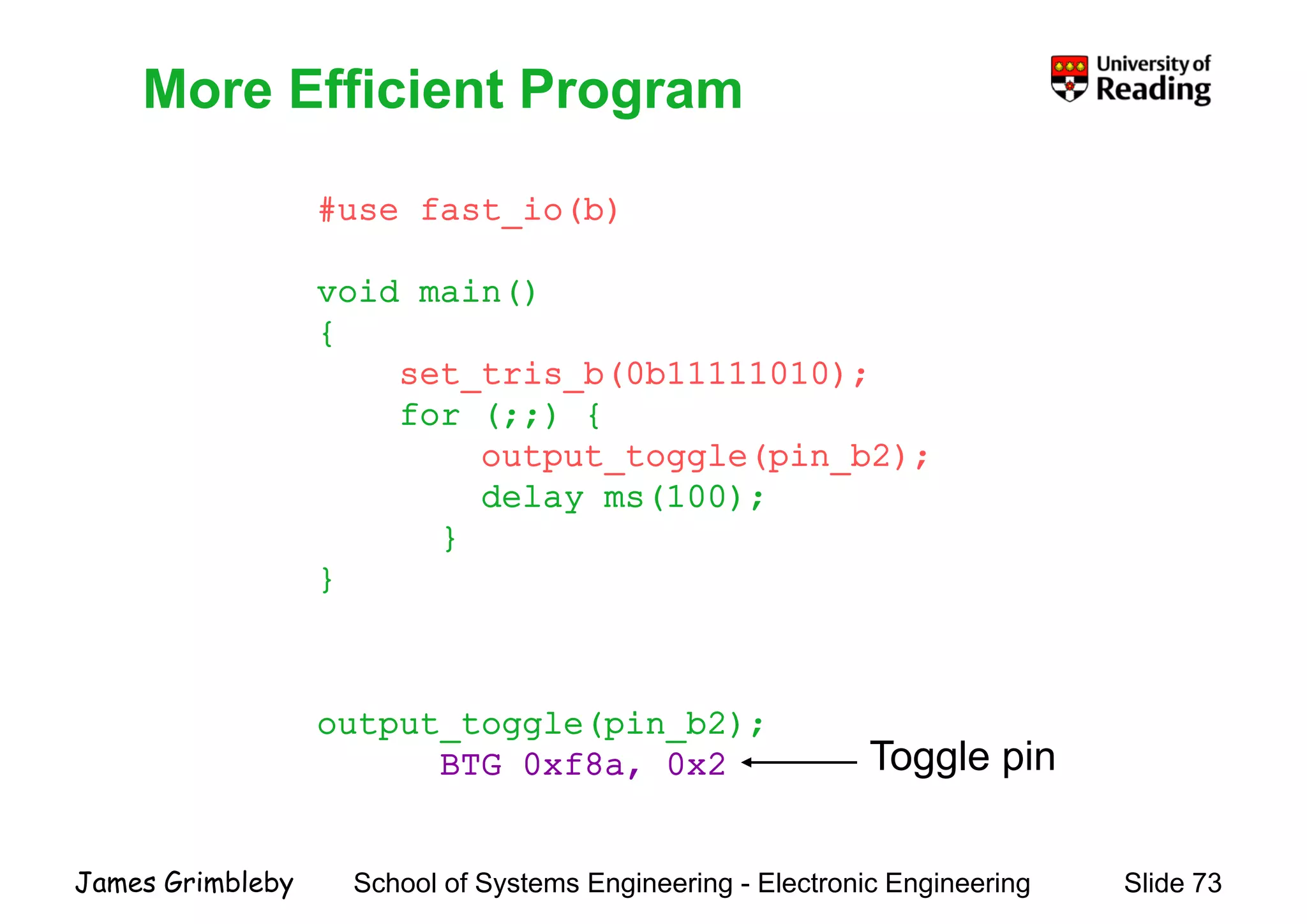
    More Efficient Program #usefast io(b) More Efficient Program #use fast_io(b) void main() { set_tris_b(0b11111010); for (;;) {for (;;) { output_toggle(pin_b2); delay_ms(100);y } } output toggle(pin b2);output_toggle(pin_b2); BTG 0xf8a, 0x2 Toggle pin School of Systems Engineering - Electronic Engineering Slide 73James Grimbleby
  • 74.
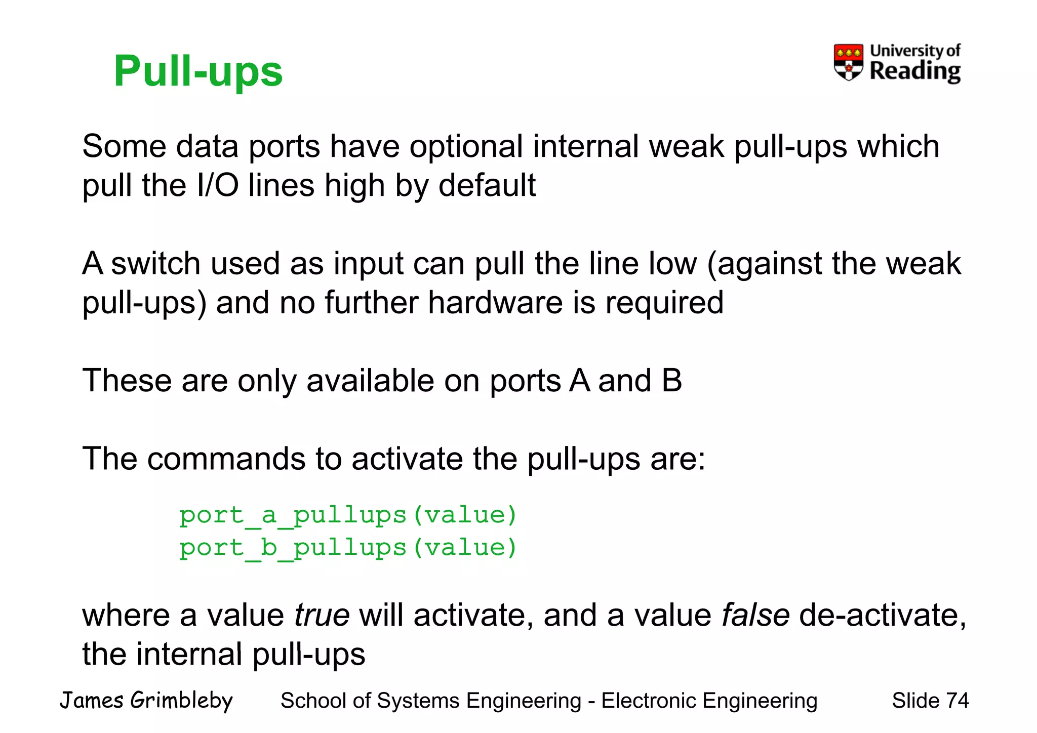
    Pull-ups Some data portshave optional internal weak pull-ups which Pull ups p p p p pull the I/O lines high by default A switch used as input can pull the line low (against the weak pull-ups) and no further hardware is required These are only available on ports A and B The commands to activate the pull-ups are: port_a_pullups(value) port_b_pullups(value) where a value true will activate, and a value false de-activate, the internal pull ups School of Systems Engineering - Electronic Engineering Slide 74James Grimbleby the internal pull-ups
  • 75.
    Programming PIC MicrocontrollersProgrammingPIC Microcontrollers Lecture 4 Timer/Counter/PWMTimer/Counter/PWM School of Systems Engineering - Electronic Engineering Slide 75James Grimbleby
  • 76.
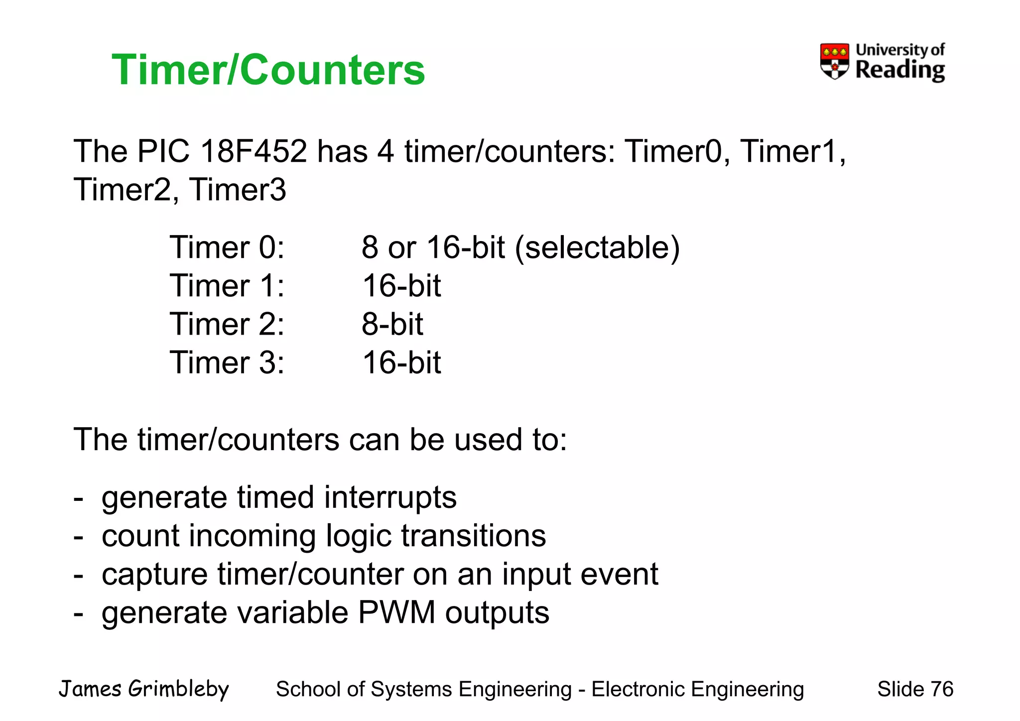
    Timer/Counters The PIC 18F452has 4 timer/counters: Timer0, Timer1, Timer/Counters The PIC 18F452 has 4 timer/counters: Timer0, Timer1, Timer2, Timer3 Ti 0 8 16 bit ( l t bl )Timer 0: 8 or 16-bit (selectable) Timer 1: 16-bit Timer 2: 8 bitTimer 2: 8-bit Timer 3: 16-bit The timer/counters can be used to: - generate timed interrupts - count incoming logic transitions - capture timer/counter on an input event - generate variable PWM outputs School of Systems Engineering - Electronic Engineering Slide 76James Grimbleby
  • 77.
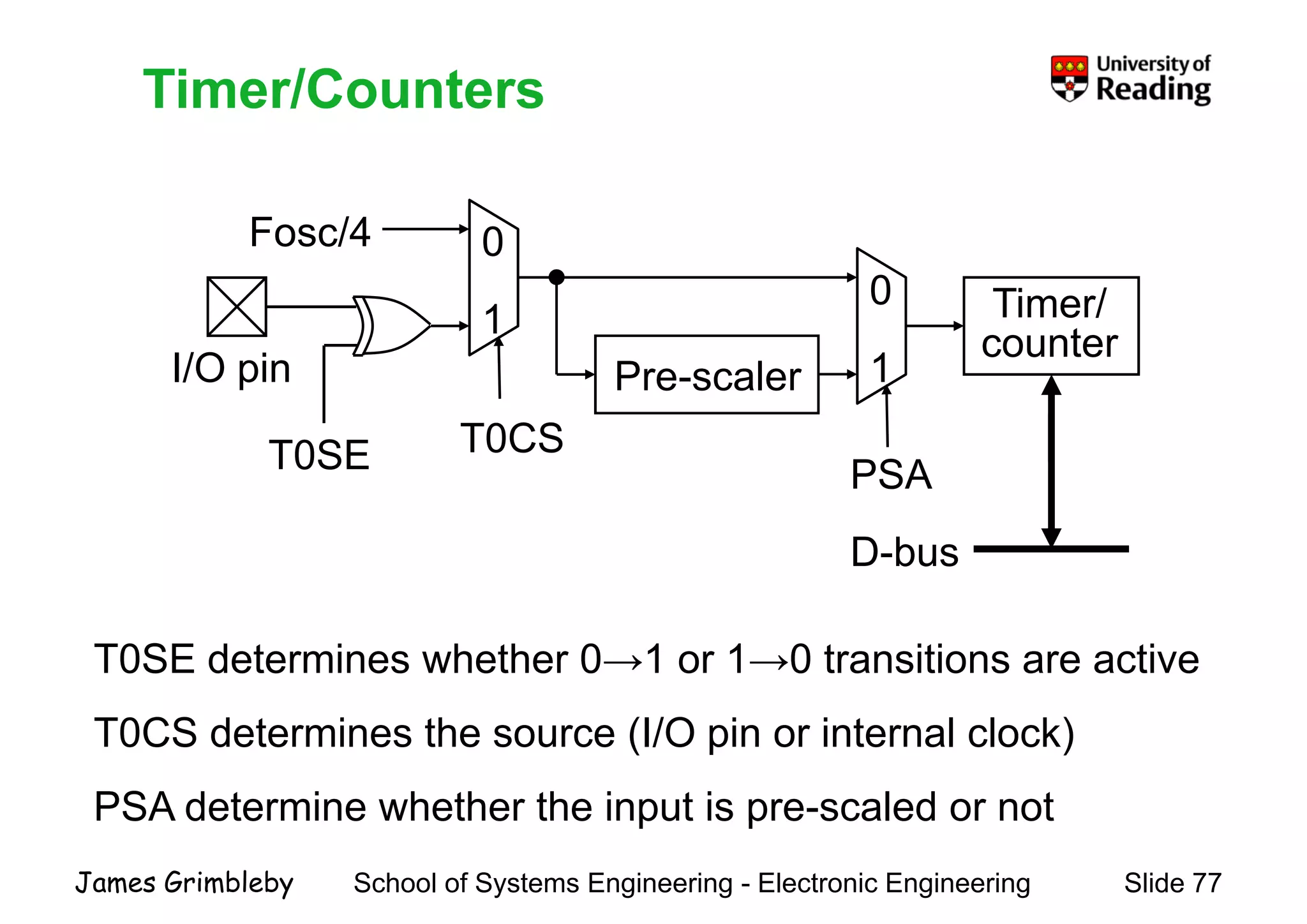
    Timer/CountersTimer/Counters 0 0 1 Timer/ Fosc/4 I/O pinPre-scaler 1 1 Timer/ counter PSA T0CST0SE D-bus T0SE determines whether 0→1 or 1→0 transitions are active T0CS d i h (I/O i i l l k)T0CS determines the source (I/O pin or internal clock) PSA determine whether the input is pre-scaled or not School of Systems Engineering - Electronic Engineering Slide 77James Grimbleby PSA determine whether the input is pre scaled or not
  • 78.
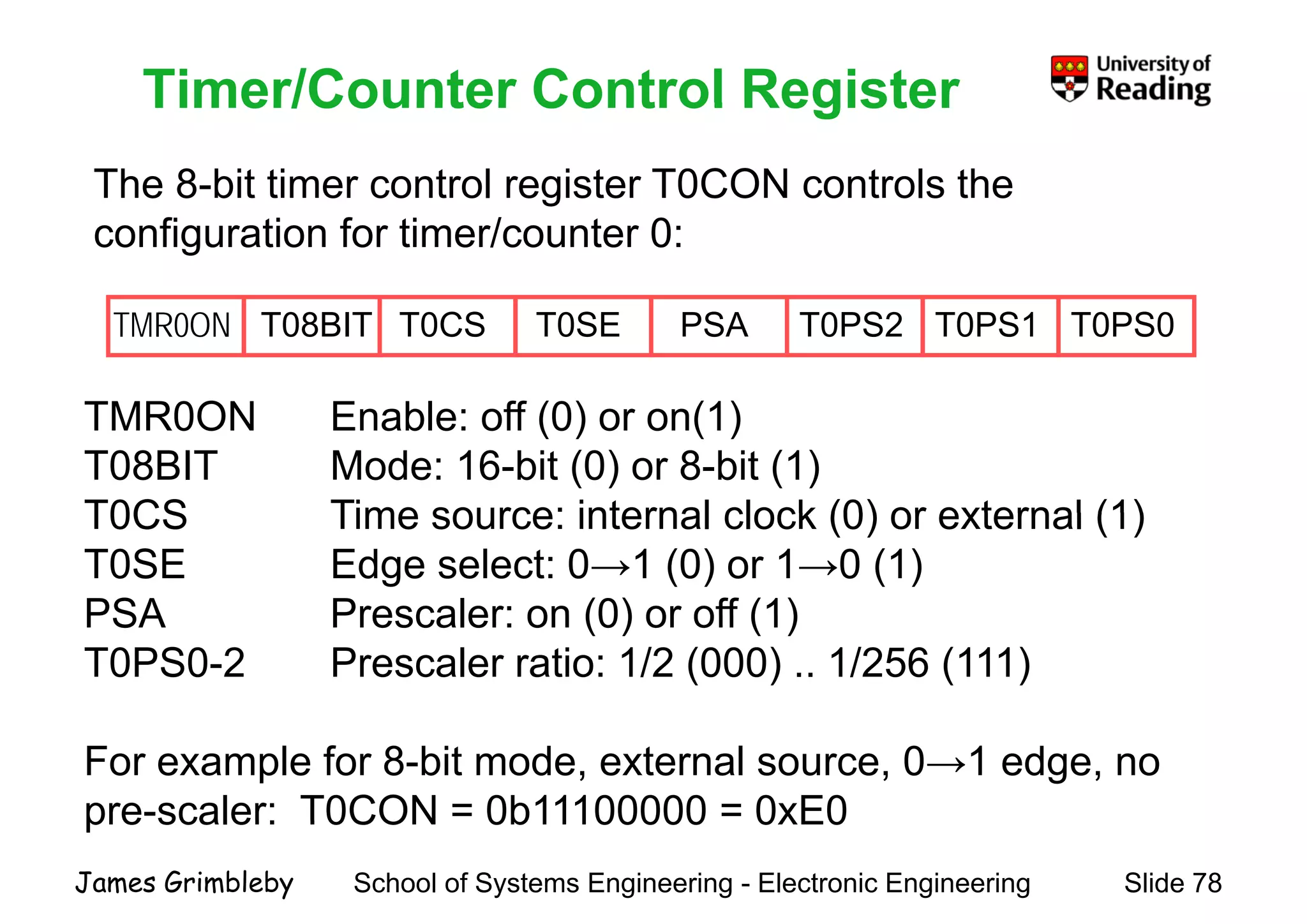
    Timer/Counter Control Register The8-bit timer control register T0CON controls the Timer/Counter Control Register g configuration for timer/counter 0: TMR0ON Enable: off (0) or on(1) T0PS0T0PS1T0PS2PSAT0SET0CST08BITTMR0ON TMR0ON Enable: off (0) or on(1) T08BIT Mode: 16-bit (0) or 8-bit (1) T0CS Time source: internal clock (0) or external (1)T0CS Time source: internal clock (0) or external (1) T0SE Edge select: 0→1 (0) or 1→0 (1) PSA Prescaler: on (0) or off (1)PSA Prescaler: on (0) or off (1) T0PS0-2 Prescaler ratio: 1/2 (000) .. 1/256 (111) For example for 8-bit mode, external source, 0→1 edge, no pre-scaler: T0CON = 0b11100000 = 0xE0 School of Systems Engineering - Electronic Engineering Slide 78James Grimbleby pre scaler: T0CON 0b11100000 0xE0
  • 79.
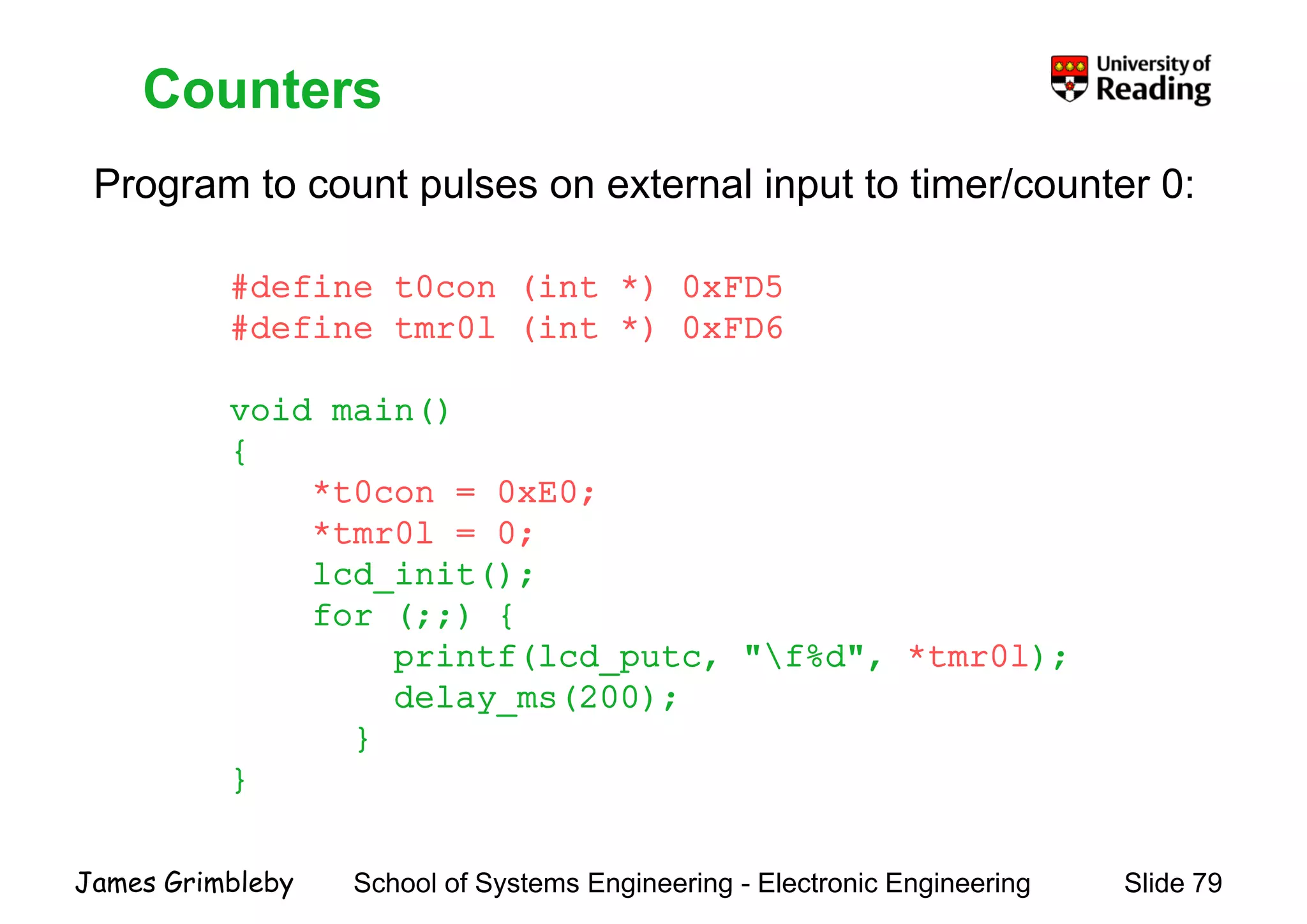
    Counters Program to countpulses on external input to timer/counter 0: Counters #define t0con (int *) 0xFD5 g p p #define tmr0l (int *) 0xFD6 void main()void main() { *t0con = 0xE0; *tmr0l = 0; lcd_init(); for (;;) {for (;;) { printf(lcd_putc, "f%d", *tmr0l); delay_ms(200); } } School of Systems Engineering - Electronic Engineering Slide 79James Grimbleby
  • 80.
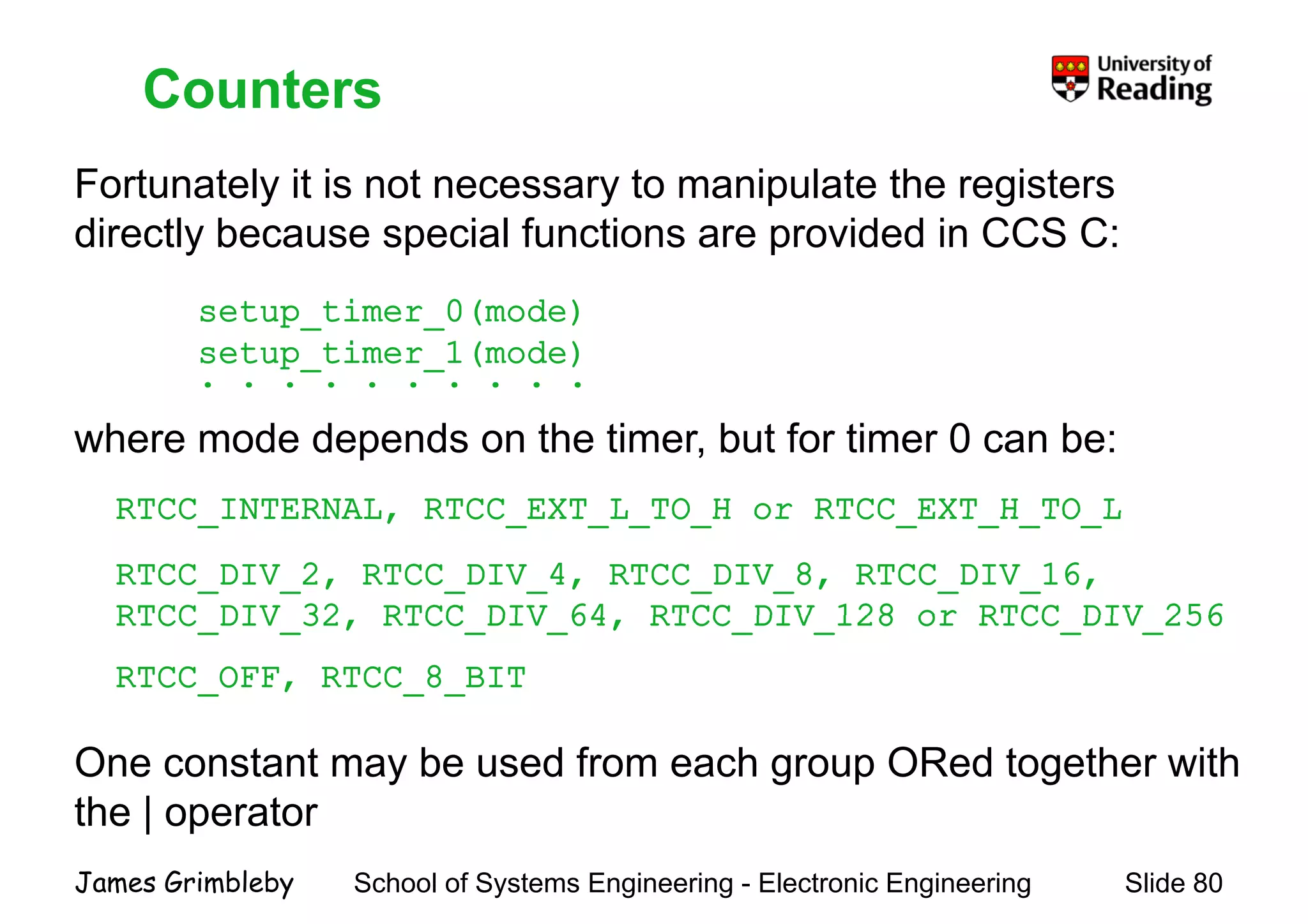
    Counters Fortunately it isnot necessary to manipulate the registers Counters y y p g directly because special functions are provided in CCS C: setup timer 0(mode)setup_timer_0(mode) setup_timer_1(mode) . . . . . . . . . . where mode depends on the timer, but for timer 0 can be: RTCC INTERNAL RTCC EXT L TO H or RTCC EXT H TO LRTCC_INTERNAL, RTCC_EXT_L_TO_H or RTCC_EXT_H_TO_L RTCC_DIV_2, RTCC_DIV_4, RTCC_DIV_8, RTCC_DIV_16, RTCC DIV 32 RTCC DIV 64 RTCC DIV 128 or RTCC DIV 256RTCC_DIV_32, RTCC_DIV_64, RTCC_DIV_128 or RTCC_DIV_256 RTCC_OFF, RTCC_8_BIT One constant may be used from each group ORed together with the | operator School of Systems Engineering - Electronic Engineering Slide 80James Grimbleby the | operator
  • 81.
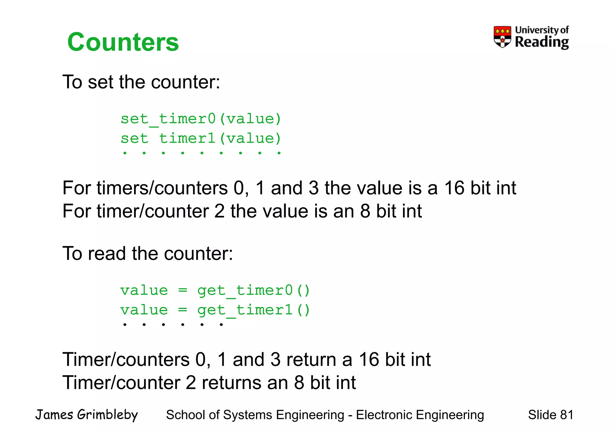
    Counters To set thecounter: Counters set_timer0(value) set_timer1(value)( ) . . . . . . . . . For timers/counters 0, 1 and 3 the value is a 16 bit intFor timers/counters 0, 1 and 3 the value is a 16 bit int For timer/counter 2 the value is an 8 bit int To read the counter: value = get timer0()value = get_timer0() value = get_timer1() . . . . . . Timer/counters 0, 1 and 3 return a 16 bit int Timer/counter 2 returns an 8 bit int School of Systems Engineering - Electronic Engineering Slide 81James Grimbleby Timer/counter 2 returns an 8 bit int
  • 82.
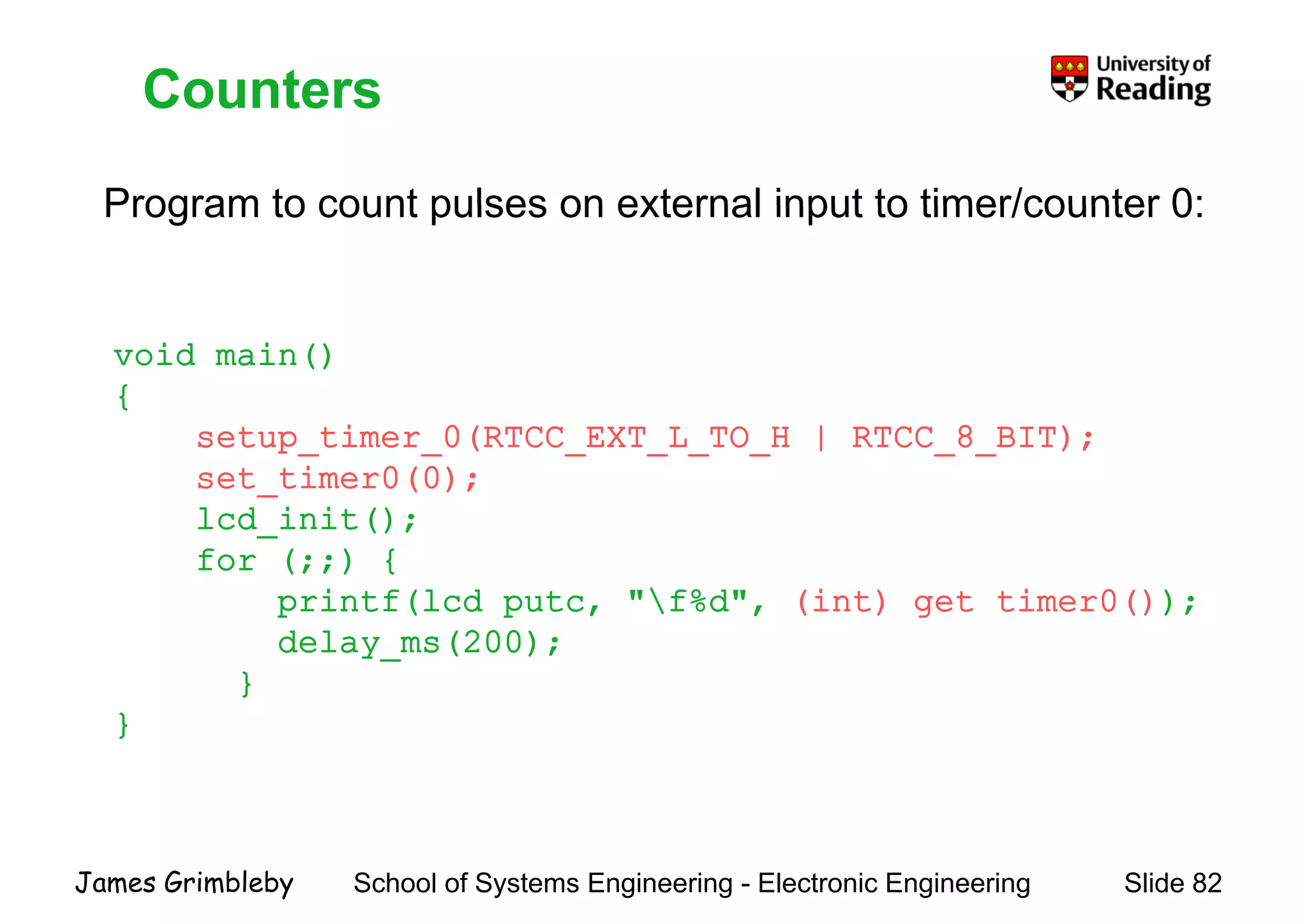
    Counters Program to countpulses on external input to timer/counter 0: Counters Program to count pulses on external input to timer/counter 0: void main() {{ setup_timer_0(RTCC_EXT_L_TO_H | RTCC_8_BIT); set_timer0(0); lcd init();lcd_init(); for (;;) { printf(lcd_putc, "f%d", (int) get_timer0());p ( p , , ( ) g ()); delay_ms(200); } }} School of Systems Engineering - Electronic Engineering Slide 82James Grimbleby
  • 83.
    Timer Interrupts Microprocessors normallyexecute code sequentially Timer Interrupts p y q y Sometimes execution must be suspended temporarily to perform some other task In PICs this happens as the result of interrupt requests An interrupt is raised when a particular condition occurs: - timer/counter overflowtimer/counter overflow - change in the state of an input line - data received on the serial bus - completion of an analogue-to-digital conversion - power supply brown-out School of Systems Engineering - Electronic Engineering Slide 83James Grimbleby p pp y
  • 84.
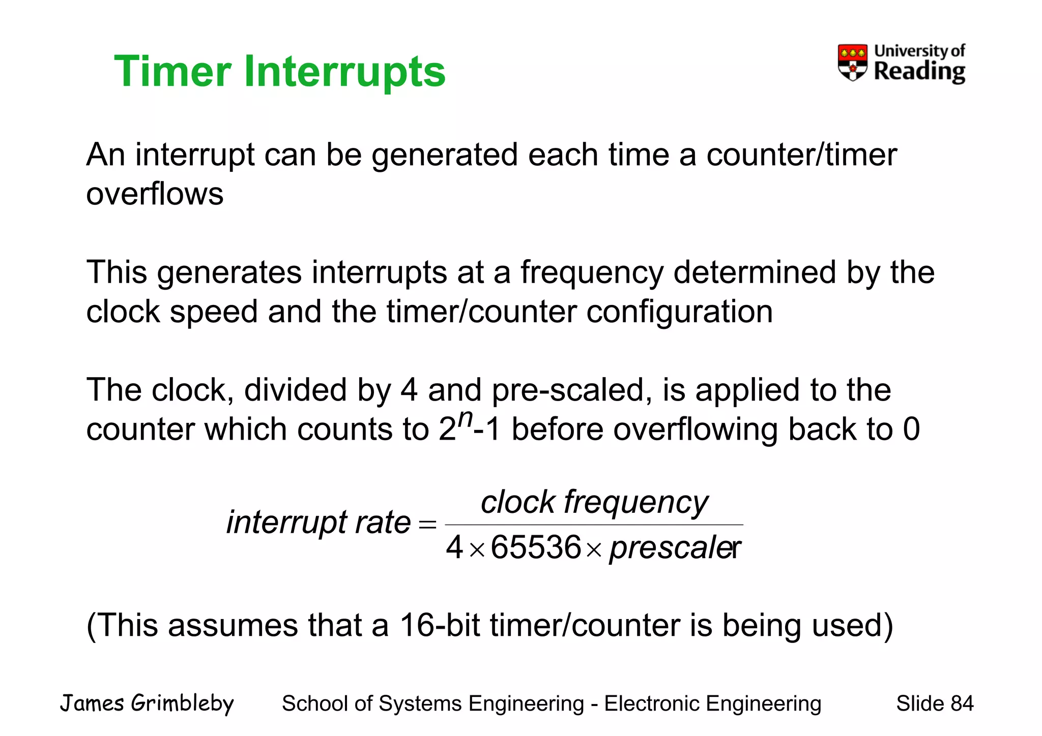
    Timer Interrupts An interruptcan be generated each time a counter/timer Timer Interrupts An interrupt can be generated each time a counter/timer overflows This generates interrupts at a frequency determined by the clock speed and the timer/counter configurationp g The clock, divided by 4 and pre-scaled, is applied to the counter which counts to 2n-1 before overflowing back to 0 fl k r655364 prescale frequencyclock rateinterrupt ×× = (This assumes that a 16-bit timer/counter is being used) School of Systems Engineering - Electronic Engineering Slide 84James Grimbleby
  • 85.
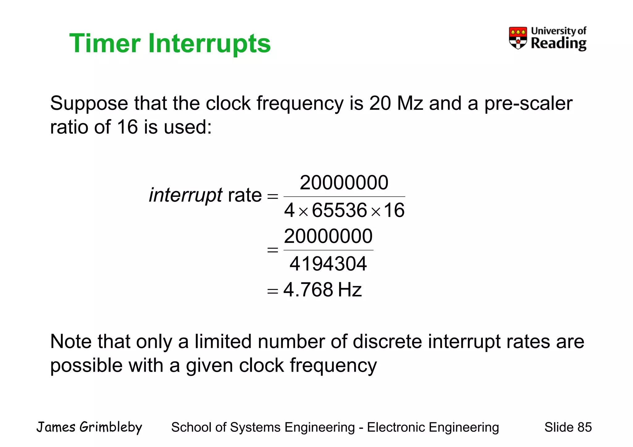
    Timer Interrupts S tht th l k f i 20 M d l Timer Interrupts Suppose that the clock frequency is 20 Mz and a pre-scaler ratio of 16 is used: 20000000 rate =interrupt 20000000 16655364 rate = ×× =interrupt Hz768.4 4194304 = = Note that only a limited number of discrete interrupt rates areNote that only a limited number of discrete interrupt rates are possible with a given clock frequency School of Systems Engineering - Electronic Engineering Slide 85James Grimbleby
  • 86.
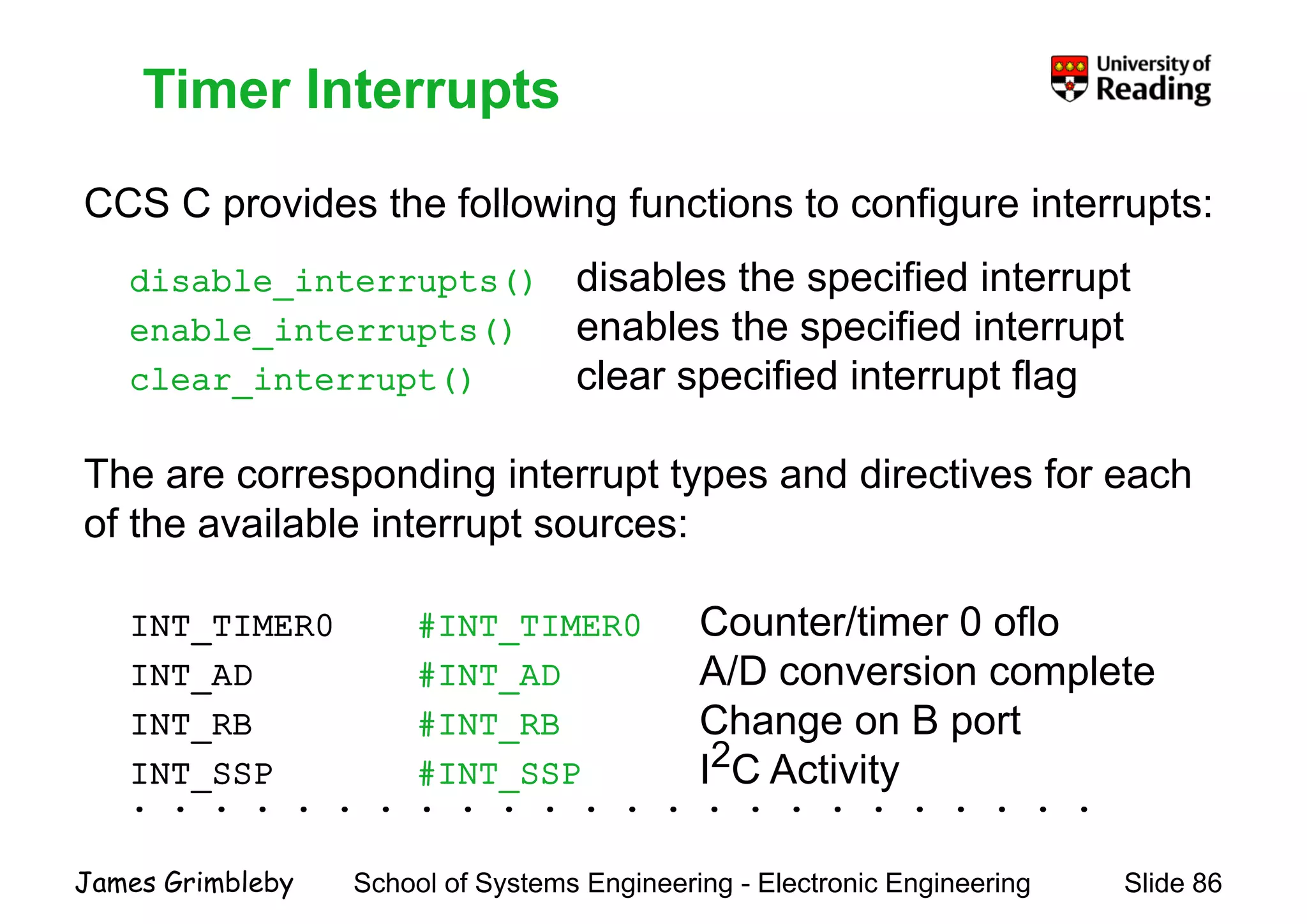
    Timer Interrupts CCS Cprovides the following functions to configure interrupts: Timer Interrupts CCS C provides the following functions to configure interrupts: disable_interrupts() disables the specified interrupt enable_interrupts() enables the specified interrupt clear_interrupt() clear specified interrupt flag The are corresponding interrupt types and directives for each f th il bl i t tof the available interrupt sources: INT TIMER0 #INT TIMER0 Counter/timer 0 ofloINT_TIMER0 #INT_TIMER0 Counter/timer 0 oflo INT_AD #INT_AD A/D conversion complete INT RB #INT RB Change on B portINT_RB #INT_RB Change on B port INT_SSP #INT_SSP I2C Activity . . . . . . . . . . . . . . . . . . . . . . . . School of Systems Engineering - Electronic Engineering Slide 86James Grimbleby
  • 87.
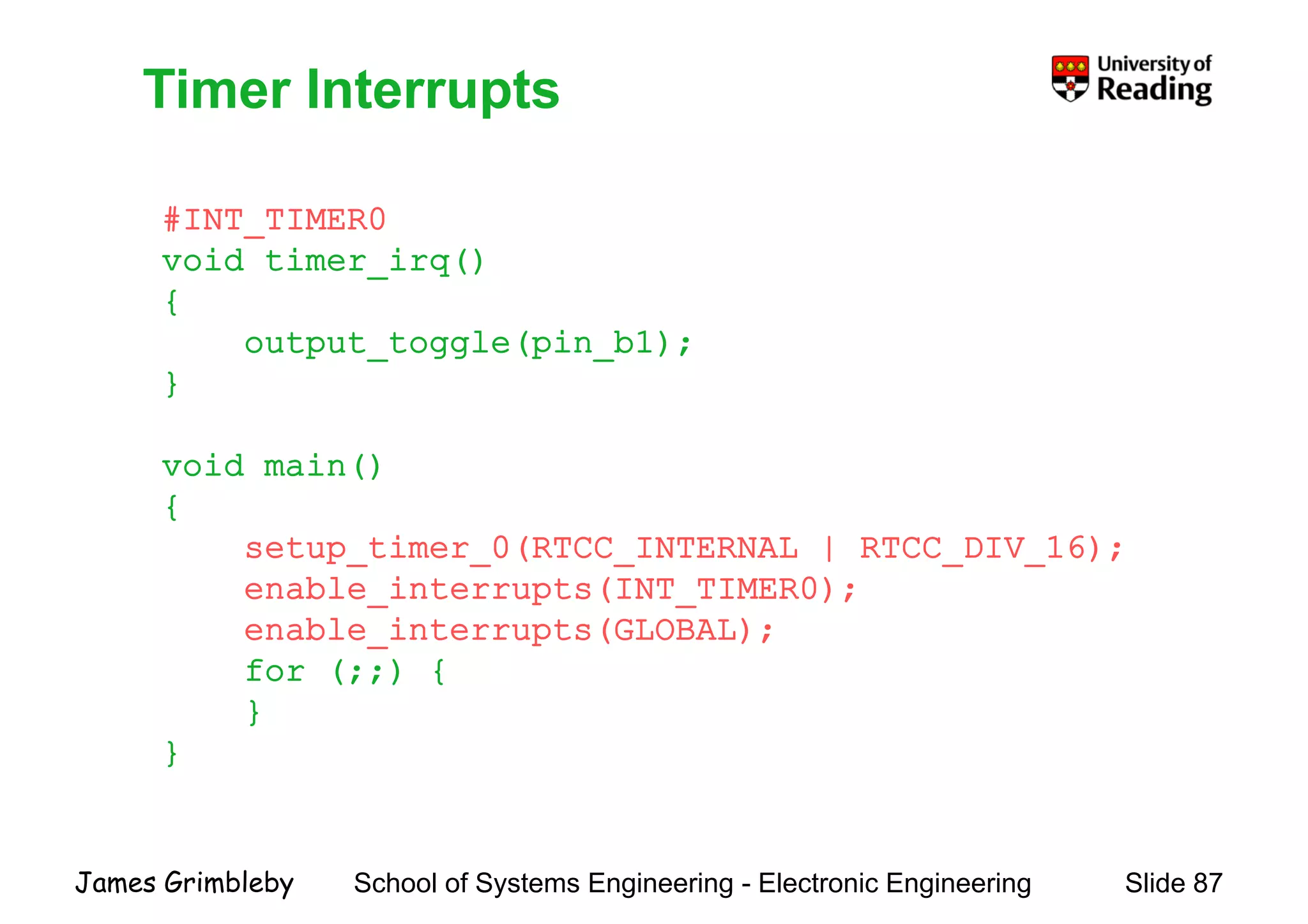
    Timer Interrupts # 0 TimerInterrupts #INT_TIMER0 void timer_irq() {{ output_toggle(pin_b1); } void main() {{ setup_timer_0(RTCC_INTERNAL | RTCC_DIV_16); enable_interrupts(INT_TIMER0); bl i ( )enable_interrupts(GLOBAL); for (;;) { }} } School of Systems Engineering - Electronic Engineering Slide 87James Grimbleby
  • 88.
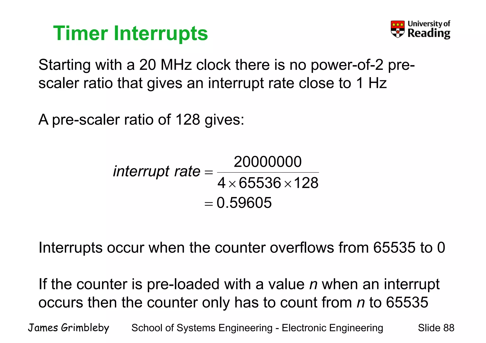
    Timer Interrupts Starting witha 20 MHz clock there is no power-of-2 pre- Timer Interrupts scaler ratio that gives an interrupt rate close to 1 Hz A l ti f 128 iA pre-scaler ratio of 128 gives: 128655364 20000000 ×× =rateinterrupt 59605.0= Interrupts occur when the counter overflows from 65535 to 0 If the counter is pre-loaded with a value n when an interrupt occurs then the counter only has to count from n to 65535 School of Systems Engineering - Electronic Engineering Slide 88James Grimbleby occurs then the counter only has to count from n to 65535
  • 89.
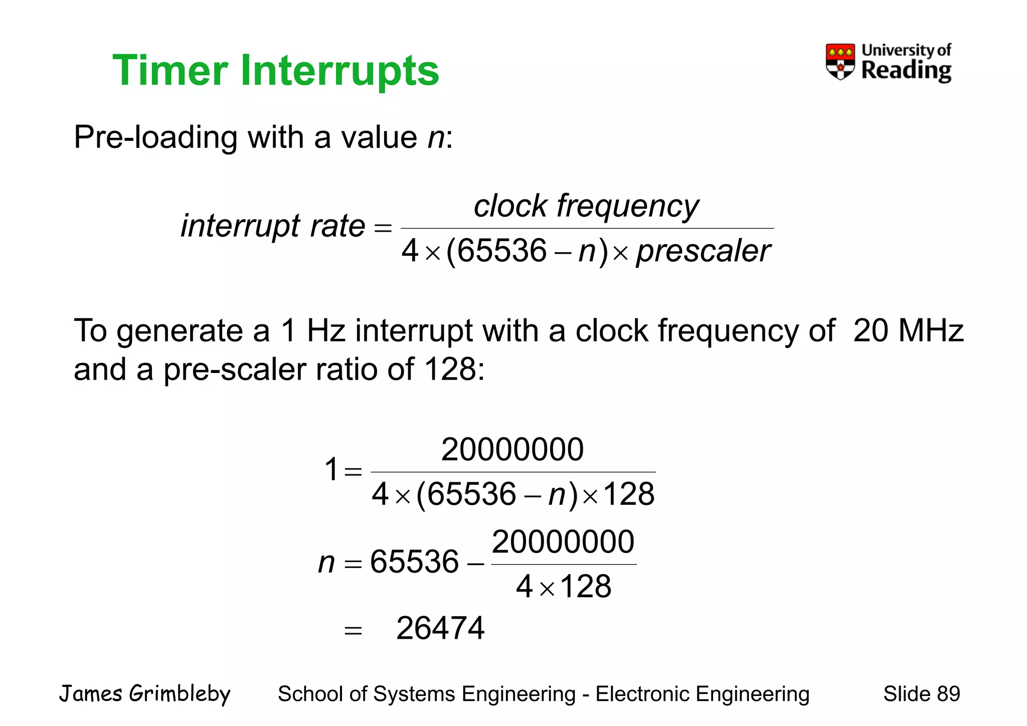
    Timer Interrupts Pre-loading witha value n: Timer Interrupts l uencyclock freq rateinterrupt = )65536(4 T t 1 H i t t ith l k f f 20 MH prescalern p ×−× )65536(4 To generate a 1 Hz interrupt with a clock frequency of 20 MHz and a pre-scaler ratio of 128: 128)65536(4 20000000 1= 20000000 65536 128)65536(4 −= ×−× n n 26474 1284 65536 = × −=n School of Systems Engineering - Electronic Engineering Slide 89James Grimbleby
  • 90.
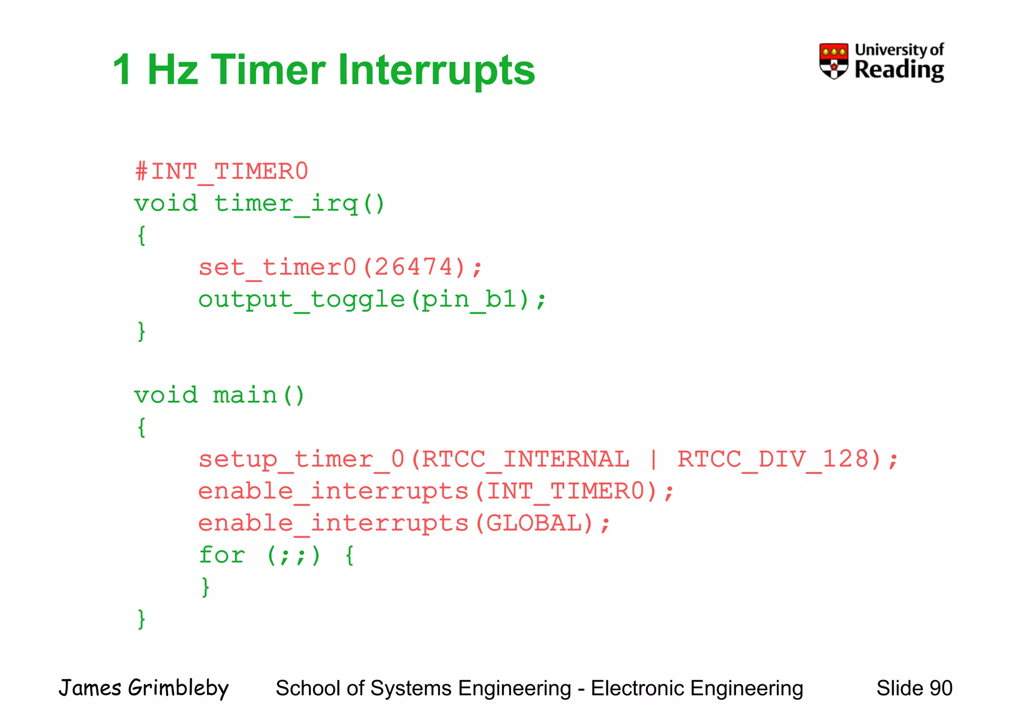
    1 Hz TimerInterrupts # 0 1 Hz Timer Interrupts #INT_TIMER0 void timer_irq() {{ set_timer0(26474); output_toggle(pin_b1); }} void main()void main() { setup_timer_0(RTCC_INTERNAL | RTCC_DIV_128); bl i ( 0)enable_interrupts(INT_TIMER0); enable_interrupts(GLOBAL); for (;;) {for (;;) { } } School of Systems Engineering - Electronic Engineering Slide 90James Grimbleby
  • 91.
    Pulse-Width Modulation Pulse-width modulation(PWM) can be used to create an n-bit Pulse Width Modulation digital-to-analogue converter (DAC) A t l ith i k ti (d t l ) iA rectangular wave with a given mark-space ratio (duty cycle) is generated and this is applied to a 1-bit DAC DACs of this type have only a limited bandwidth because of the need to filter out the rectangular waveneed to filter out the rectangular wave. Typical applications are in dc motor control brightness controlTypical applications are in dc motor control, brightness control of lights and in dc-dc converters The PIC18F452 has a PWM generator that make use of counter/timer 2 School of Systems Engineering - Electronic Engineering Slide 91James Grimbleby counter/timer 2
  • 92.
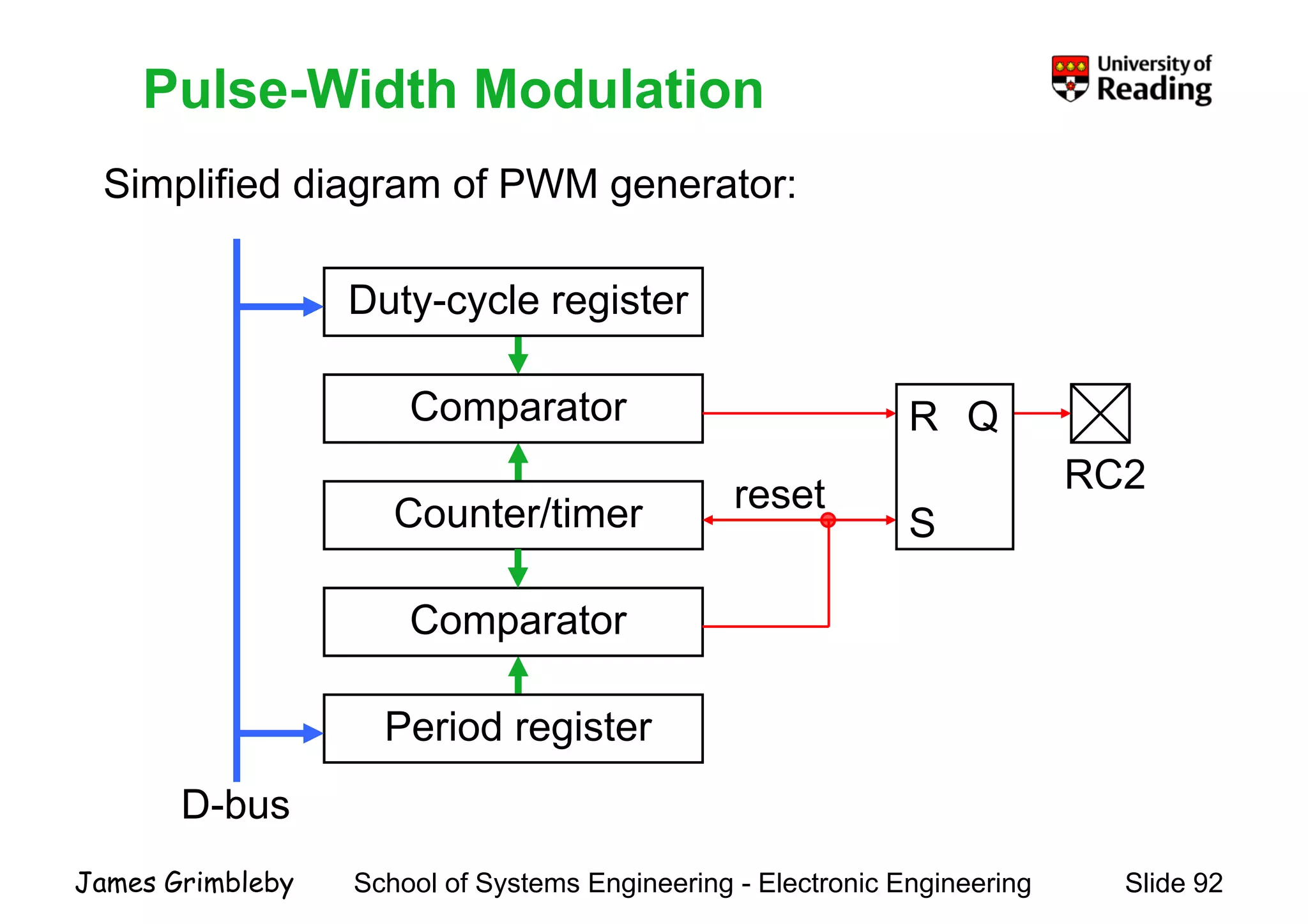
    Pulse-Width Modulation Simplified diagramof PWM generator: Pulse Width Modulation Duty-cycle register p g g Comparator Duty cycle register R Q RC2 Comparator Counter/timer reset S R Q Counter/timer Comparator S Comparator P i d i t D-bus Period register School of Systems Engineering - Electronic Engineering Slide 92James Grimbleby
  • 93.
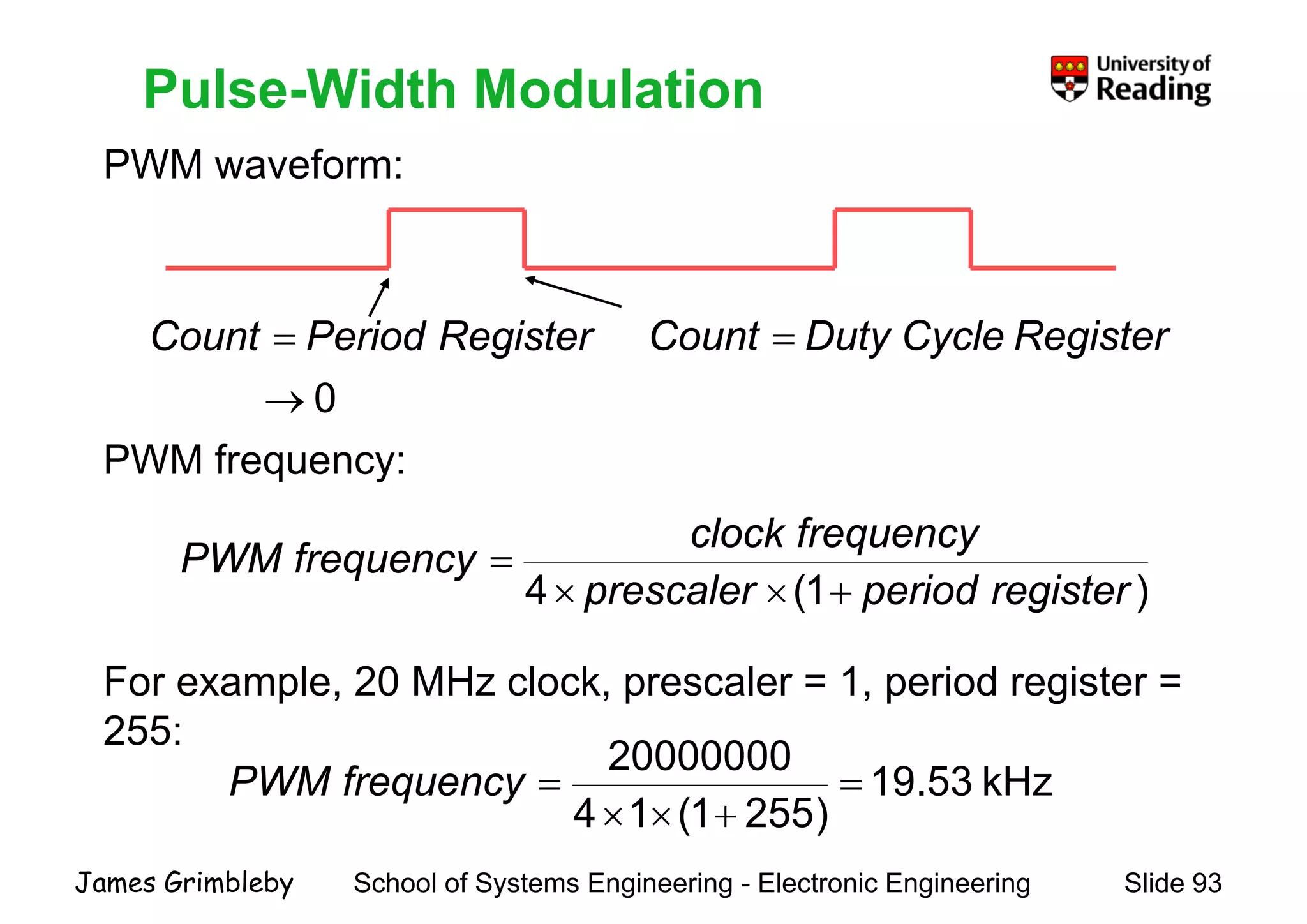
    Pulse-Width Modulation PWM waveform: PulseWidth Modulation RegisterCycleDutyCount = 0→ = RegisterPeriodCount PWM frequency: 0→ )1(4 registerperiodprescaler frequencyclock frequencyPWM +×× = For example, 20 MHz clock, prescaler = 1, period register = 255255: kHz53.19 )2551(14 20000000 = +×× =frequencyPWM School of Systems Engineering - Electronic Engineering Slide 93James Grimbleby )2551(14 +××
  • 94.
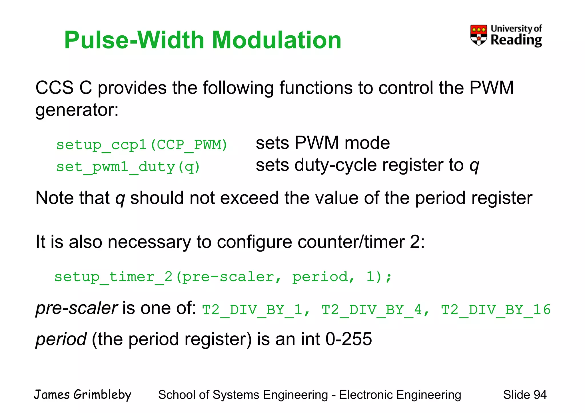
    Pulse-Width Modulation CCS Cprovides the following functions to control the PWM Pulse Width Modulation CCS C provides the following functions to control the PWM generator: ( ) t PWM dsetup_ccp1(CCP_PWM) sets PWM mode set_pwm1_duty(q) sets duty-cycle register to q Note that q should not exceed the value of the period register It is also necessary to configure counter/timer 2: setup timer 2(pre scaler period 1);setup_timer_2(pre-scaler, period, 1); pre-scaler is one of: T2_DIV_BY_1, T2_DIV_BY_4, T2_DIV_BY_16 period (the period register) is an int 0-255 School of Systems Engineering - Electronic Engineering Slide 94James Grimbleby
  • 95.
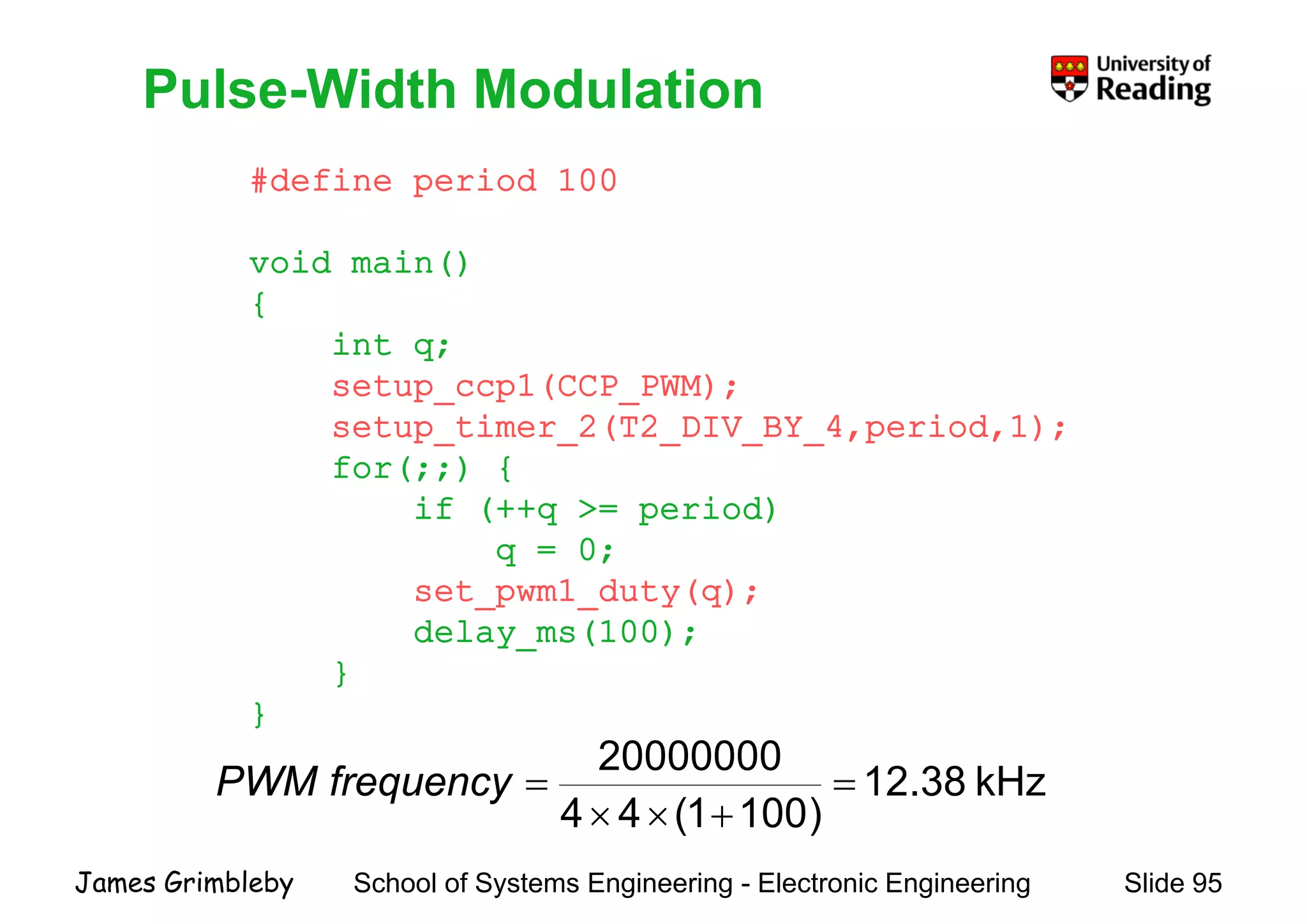
    Pulse-Width Modulation #define period100 Pulse Width Modulation void main() {{ int q; setup_ccp1(CCP_PWM); setup_timer_2(T2_DIV_BY_4,period,1); for(;;) { if (++q >= period)if (++q >= period) q = 0; set_pwm1_duty(q); delay_ms(100); } }} kHz38.12 )1001(44 20000000 = +×× =frequencyPWM School of Systems Engineering - Electronic Engineering Slide 95James Grimbleby )1001(44 +××
  • 96.
    Programming PIC MicrocontrollersProgrammingPIC Microcontrollers Lecture 5Lecture 5 LCD, RS232, ADC,, , , I2C, EEPROMI C, EEPROM School of Systems Engineering - Electronic Engineering Slide 96James Grimbleby
  • 97.
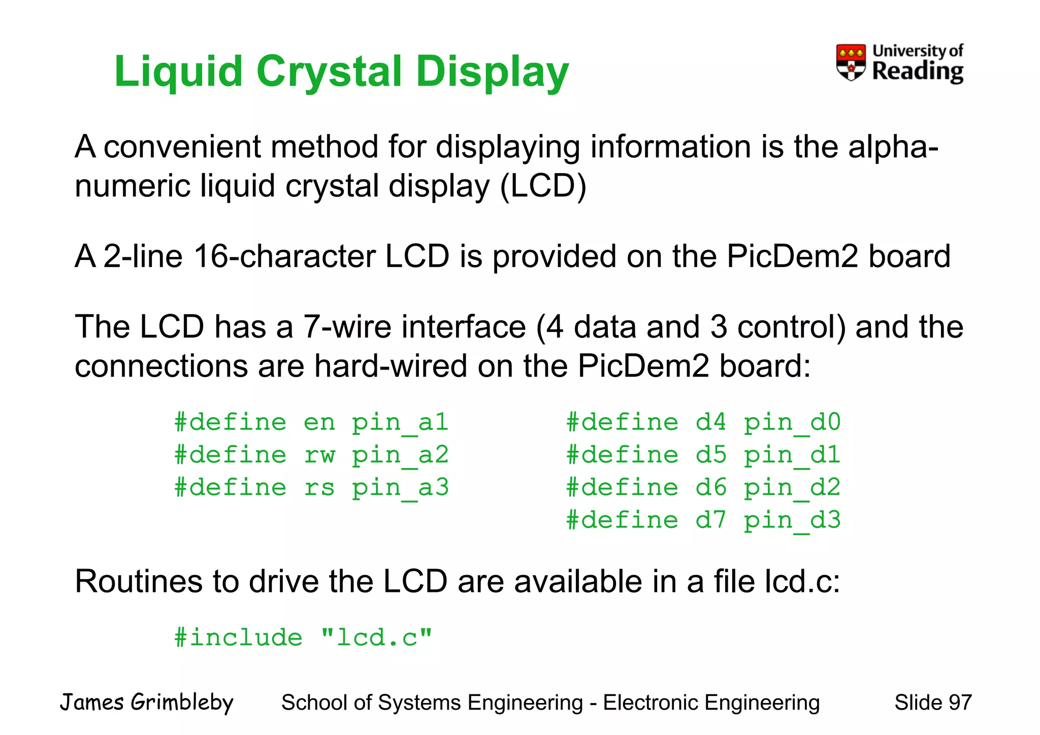
    Liquid Crystal Display Aconvenient method for displaying information is the alpha- Liquid Crystal Display p y g p numeric liquid crystal display (LCD) A 2 li 16 h t LCD i id d th Pi D 2 b dA 2-line 16-character LCD is provided on the PicDem2 board The LCD has a 7 wire interface (4 data and 3 control) and theThe LCD has a 7-wire interface (4 data and 3 control) and the connections are hard-wired on the PicDem2 board: #define en pin_a1 #define d4 pin_d0 #define rw pin_a2 #define d5 pin_d1 #define rs pin a3 #define d6 pin d2#define rs pin_a3 #define d6 pin_d2 #define d7 pin_d3 R ti t d i th LCD il bl i fil l dRoutines to drive the LCD are available in a file lcd.c: #include "lcd.c" School of Systems Engineering - Electronic Engineering Slide 97James Grimbleby
  • 98.
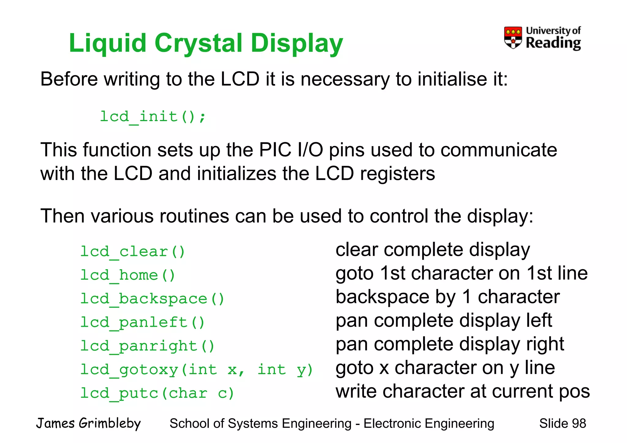
    Liquid Crystal Display Beforewriting to the LCD it is necessary to initialise it: Liquid Crystal Display lcd_init(); This function sets up the PIC I/O pins used to communicateThis function sets up the PIC I/O pins used to communicate with the LCD and initializes the LCD registers Then various routines can be used to control the display: l d l () clear complete displaylcd_clear() clear complete display lcd_home() goto 1st character on 1st line lcd backspace() backspace by 1 characterlcd_backspace() backspace by 1 character lcd_panleft() pan complete display left lcd panright() pan complete display rightlcd_panright() pan complete display right lcd_gotoxy(int x, int y) goto x character on y line lcd putc(char c) write character at current pos School of Systems Engineering - Electronic Engineering Slide 98James Grimbleby lcd_putc(char c) write character at current pos
  • 99.
    Liquid Crystal Display Inmost cases it is convenient to use the printf() (print Liquid Crystal Display formatted) function for all output to the LCD, for example: printf(lcd_putc, "fTime = %d s", t);p ( p , , ); printf() can print characters, text, integers and floating-point numbers The first parameter determines the output channel in this caseThe first parameter determines the output channel, in this case the LCD The second parameter is the formatting string which determines how the following parameters ae displayeddetermines how the following parameters ae displayed Any further parameters are variables or constants to be printed School of Systems Engineering - Electronic Engineering Slide 99James Grimbleby
  • 100.
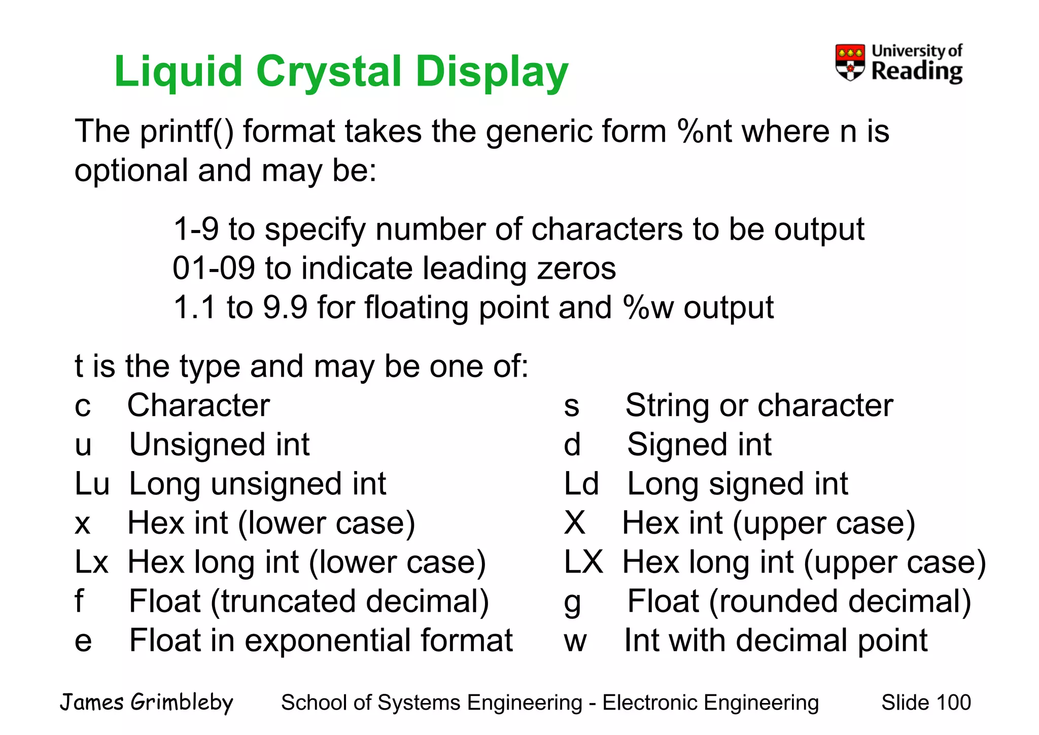
    Liquid Crystal Display Theprintf() format takes the generic form %nt where n is ti l d b Liquid Crystal Display optional and may be: 1-9 to specify number of characters to be outputp y p 01-09 to indicate leading zeros 1.1 to 9.9 for floating point and %w output t is the type and may be one of: c Character s String or characterc Character s String or character u Unsigned int d Signed int Lu Long unsigned int Ld Long signed intLu Long unsigned int Ld Long signed int x Hex int (lower case) X Hex int (upper case) Lx Hex long int (lower case) LX Hex long int (upper case)Lx Hex long int (lower case) LX Hex long int (upper case) f Float (truncated decimal) g Float (rounded decimal) e Float in exponential format w Int with decimal point School of Systems Engineering - Electronic Engineering Slide 100James Grimbleby p p
  • 101.
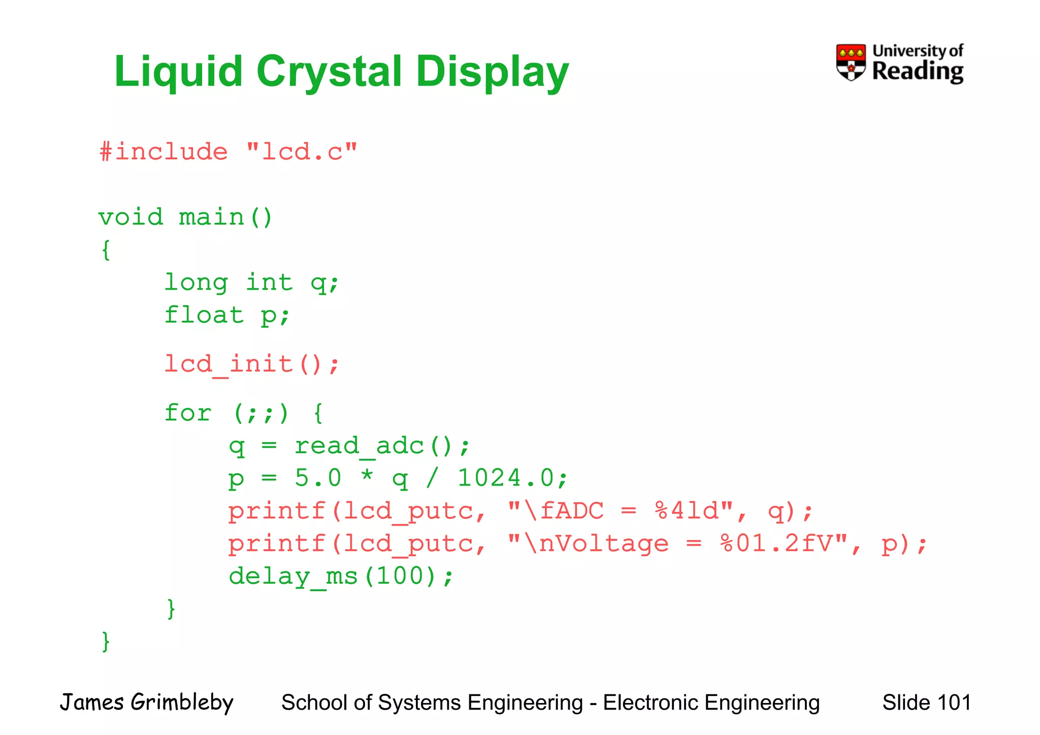
    Liquid Crystal Display #include"lcd.c" Liquid Crystal Display void main() {{ long int q; float p;p; lcd_init(); for (;;) {for (;;) { q = read_adc(); p = 5.0 * q / 1024.0;p q / ; printf(lcd_putc, "fADC = %4ld", q); printf(lcd_putc, "nVoltage = %01.2fV", p); delay ms(100);delay_ms(100); } } School of Systems Engineering - Electronic Engineering Slide 101James Grimbleby }
  • 102.
    RS232 The PIC18F452 hasa built-in Universal Synchronous RS232 The PIC18F452 has a built-in Universal Synchronous Asynchronous Receiver Transmitter (USART) This allows it to communicate using the RS232, RS422 and RS485 protocolsRS485 protocols The 5 V logic-level receive and transmit signals of the PIC aree 5 og c e e ece e a d t a s t s g a s o t e C a e converted to RS232 levels by a MAX232 device Baud rates are generated by dividing down the system clock The USART receive and transmit pins are c7 and c6 respectively School of Systems Engineering - Electronic Engineering Slide 102James Grimbleby
  • 103.
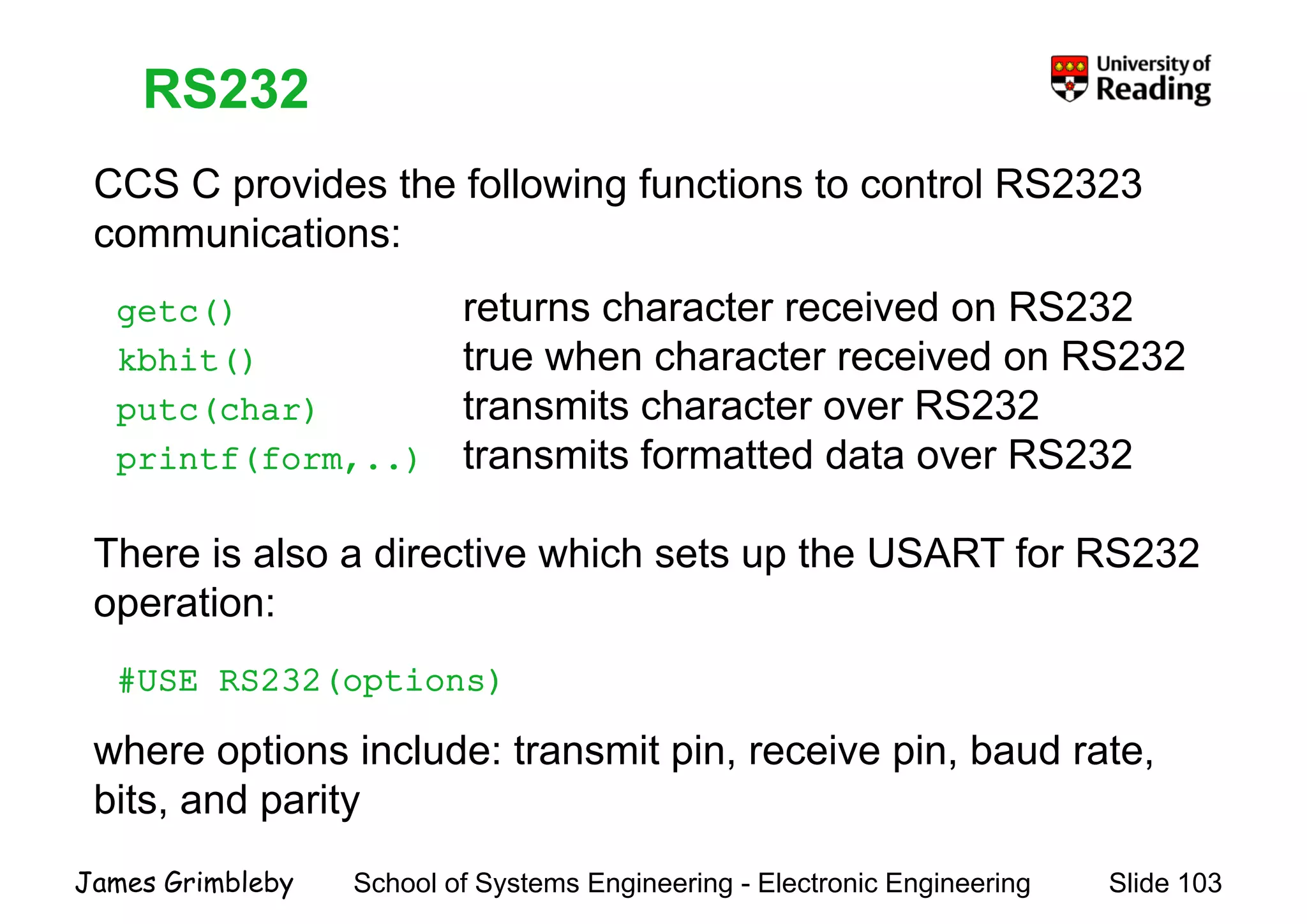
    RS232 CCS C providesthe following functions to control RS2323 RS232 p g communications: getc() returns character received on RS232getc() returns character received on RS232 kbhit() true when character received on RS232 putc(char) transmits character over RS232putc(char) transmits character over RS232 printf(form,..) transmits formatted data over RS232 There is also a directive which sets up the USART for RS232 operation:operation: #USE RS232(options) where options include: transmit pin, receive pin, baud rate, bits, and parity School of Systems Engineering - Electronic Engineering Slide 103James Grimbleby p y
  • 104.
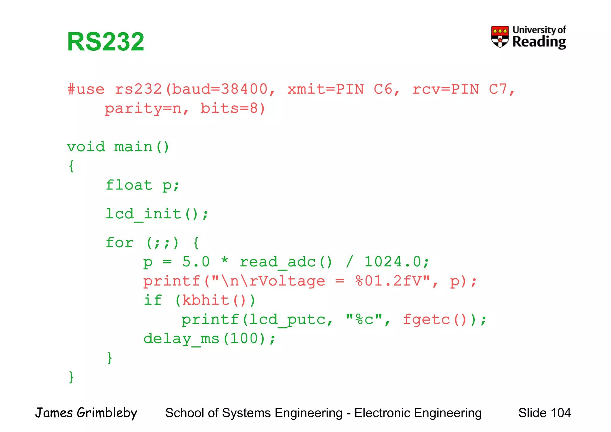
    RS232 #use rs232(baud=38400, xmit=PIN_C6,rcv=PIN_C7, RS232 , , , parity=n, bits=8) void main()void main() { float p;p; lcd_init(); for (;;) {for (;;) { p = 5.0 * read_adc() / 1024.0; printf("nrVoltage = %01.2fV", p);p ( g , p); if (kbhit()) printf(lcd_putc, "%c", fgetc()); delay ms(100);delay_ms(100); } } School of Systems Engineering - Electronic Engineering Slide 104James Grimbleby }
  • 105.
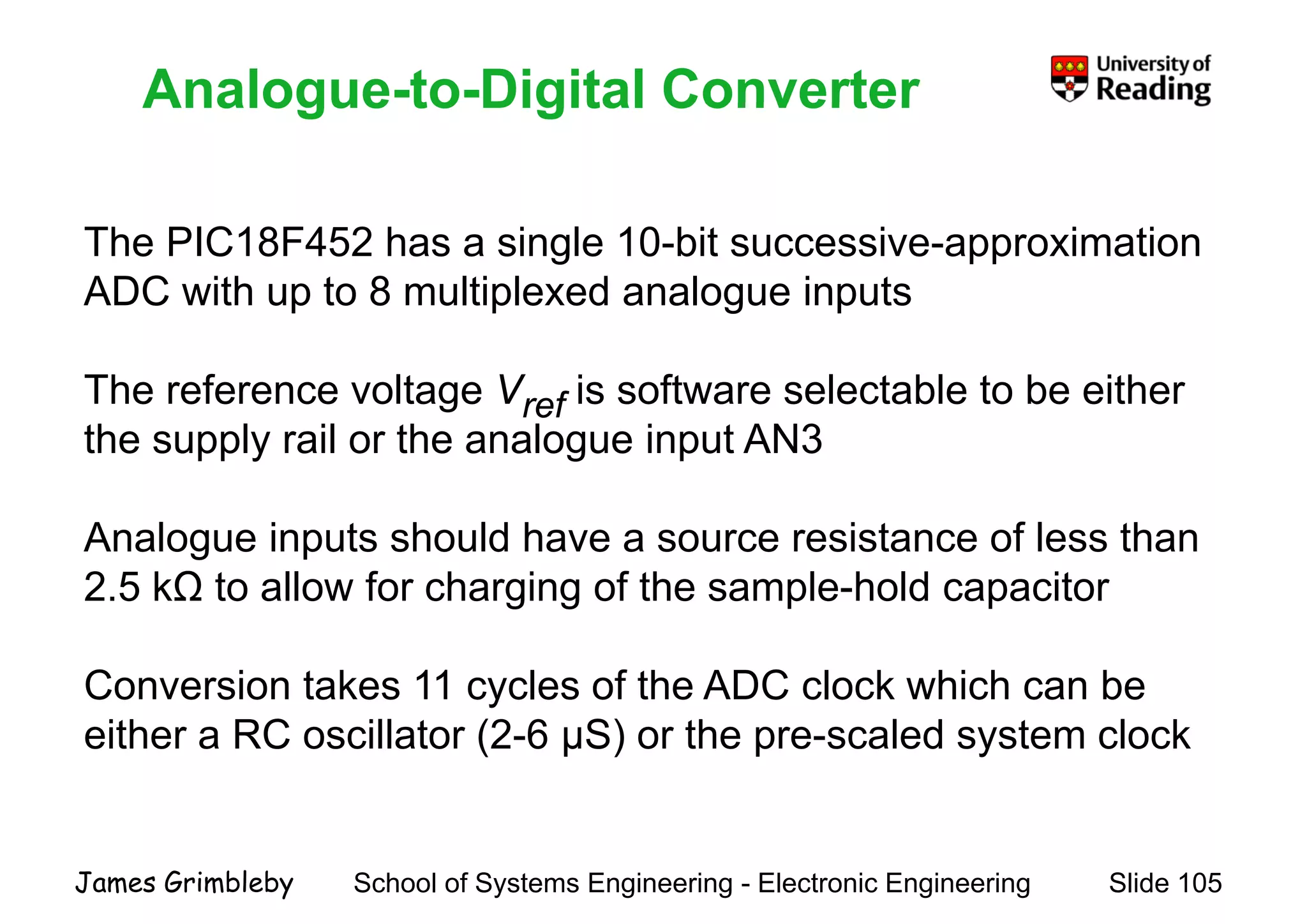
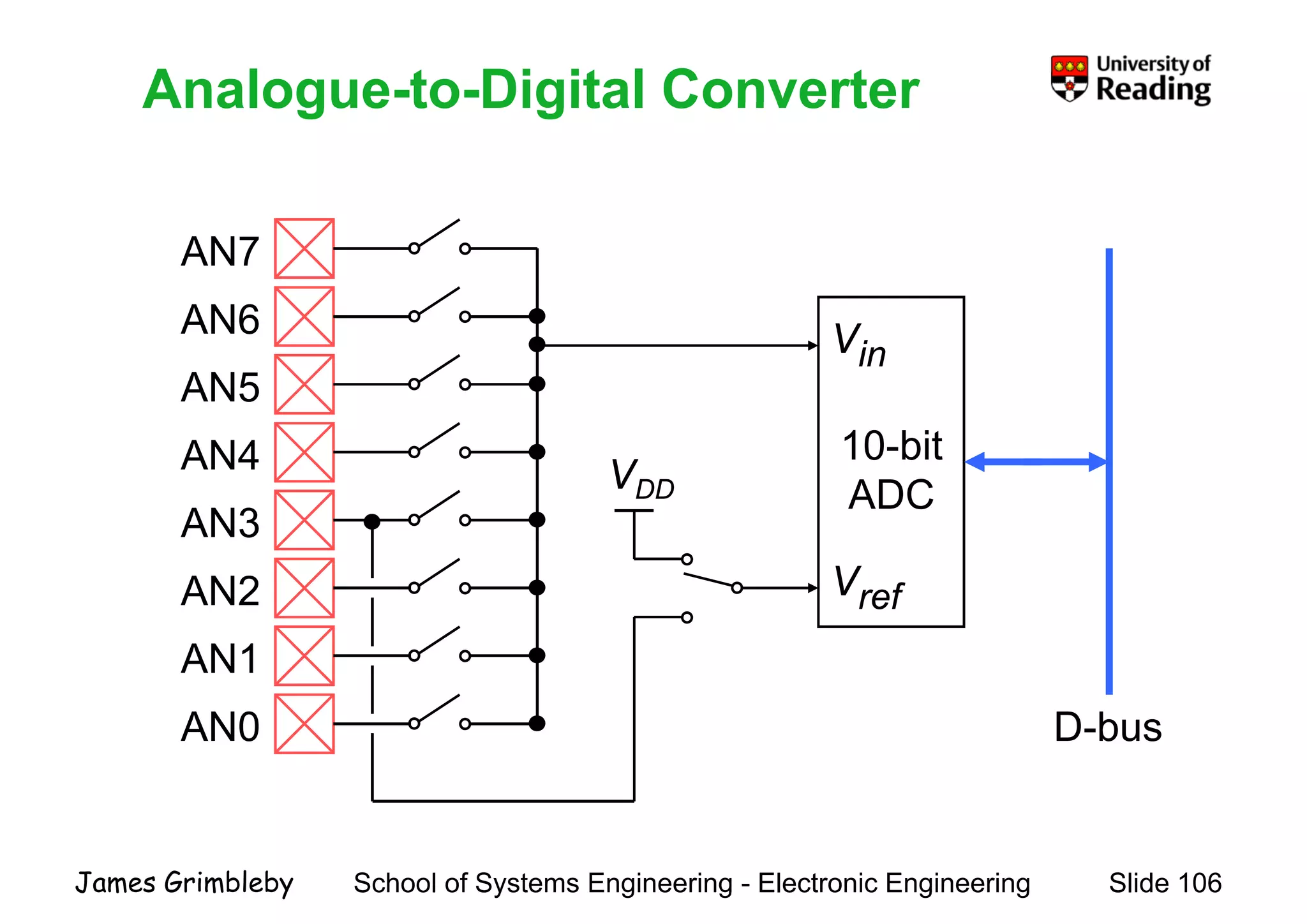
    Analogue-to-Digital ConverterAnalogue toDigital Converter The PIC18F452 has a single 10-bit successive-approximation ADC with up to 8 multiplexed analogue inputsp p g p The reference voltage Vref is software selectable to be eitherg ref the supply rail or the analogue input AN3 Analogue inputs should have a source resistance of less than 2.5 kΩ to allow for charging of the sample-hold capacitor Conversion takes 11 cycles of the ADC clock which can be either a RC oscillator (2-6 μS) or the pre-scaled system clock School of Systems Engineering - Electronic Engineering Slide 105James Grimbleby
  • 106.
    Analogue-to-Digital ConverterAnalogue toDigital Converter AN7 AN6AN6 AN5 Vin AN4 AN3 10-bit ADCVDD AN3 AN2 Vref AN1 AN0 D bAN0 D-bus School of Systems Engineering - Electronic Engineering Slide 106James Grimbleby
  • 107.
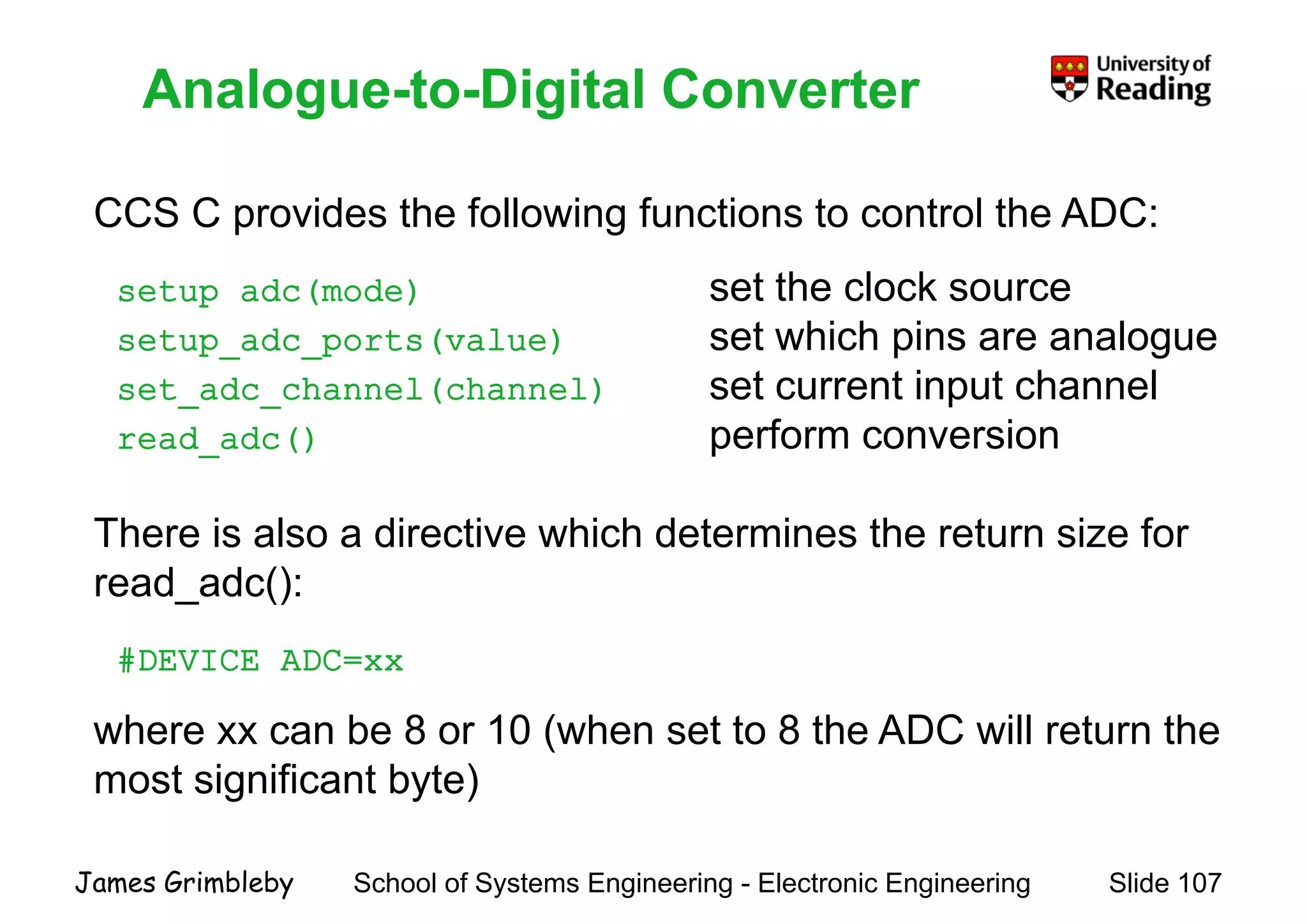
    Analogue-to-Digital Converter CCS Cid th f ll i f ti t t l th ADC Analogue to Digital Converter CCS C provides the following functions to control the ADC: setup_adc(mode) set the clock source setup_adc_ports(value) set which pins are analogue set_adc_channel(channel) set current input channel read_adc() perform conversion There is also a directive which determines the return size for read_adc(): #DEVICE ADC=xx h b 8 10 ( h t t 8 th ADC ill t thwhere xx can be 8 or 10 (when set to 8 the ADC will return the most significant byte) School of Systems Engineering - Electronic Engineering Slide 107James Grimbleby
  • 108.
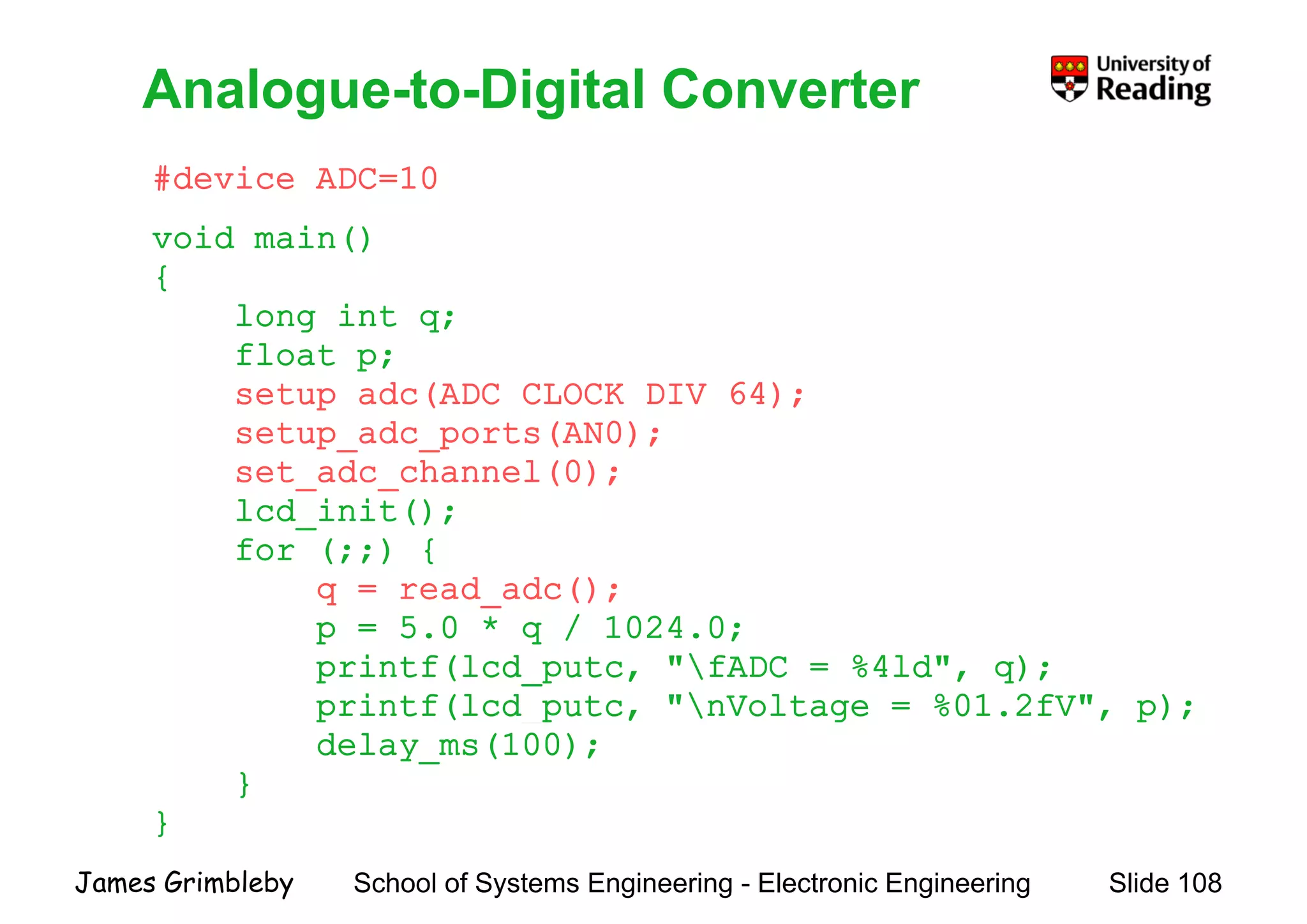
    Analogue-to-Digital Converter #device ADC=10 Analogueto Digital Converter void main() { long int q;long int q; float p; setup_adc(ADC_CLOCK_DIV_64);p setup_adc_ports(AN0); set_adc_channel(0); lcd init();lcd_init(); for (;;) { q = read_adc(); 5 0 * / 1024 0p = 5.0 * q / 1024.0; printf(lcd_putc, "fADC = %4ld", q); printf(lcd_putc, "nVoltage = %01.2fV", p);p ( _p , g , p); delay_ms(100); } } School of Systems Engineering - Electronic Engineering Slide 108James Grimbleby }
  • 109.
    EEPROM The PIC18F452 has256 byte of internal data eeprom EEPROM The PIC18F452 has 256 byte of internal data eeprom EEPROM is not directly mapped to the data space but isEEPROM is not directly mapped to the data space but is accessed indirectly through the SFR: EEADR This memory is non-volatile and can be used to store, for example, setup parameterse a p e, setup pa a ete s CCS C provides the following functions to read and write top g the EEPROM: read eeprom(address) read data from addressread_eeprom(address) read data from address write_eeprom(address, value) write data to address School of Systems Engineering - Electronic Engineering Slide 109James Grimbleby
  • 110.
    Inter-Integrated Circuit (I2C)Bus The PIC18F452 has a Master Synchronous Serial Port (MSSP) Inter Integrated Circuit (I C) Bus which can operate in either SPI or I2C mode SPI i h i l t l th t 3 i SDOSPI is a synchronous serial protocol that uses 3 wires: SDO, SDI and SCK I2C is a synchronous serial protocol that uses 2 wires: SDA and SCLSCL The PicDem2 board used in the PIC laboratory has 2 devicesThe PicDem2 board used in the PIC laboratory has 2 devices connected to the I2C bus: - a TC74 digital thermometer with I2C address 0x9A - a 24LC256 EEPROM (32 kbytes) with I2C address 0xA0 School of Systems Engineering - Electronic Engineering Slide 110James Grimbleby a 24LC256 EEPROM (32 kbytes) with I C address 0xA0
  • 111.
    Inter-Integrated Circuit (I2C)Bus CCS C provides the following functions to control I2C Inter Integrated Circuit (I C) Bus communications: i2c_start() Issues a start command on the I2C_ () i2c_write(data) Sends a single byte over the I2C i2c_read() Reads a byte over the I2Cy i2c_stop() Issues a stop command on the I2C There is also a pre-processor directive which configures the device as a Master or a Slave: #use i2c This directive also assigns the SDA and SCL pins used for the I2C interface School of Systems Engineering - Electronic Engineering Slide 111James Grimbleby
  • 112.
    24LC256 EEPROM The MicrochipTechnology 24LC256/ is a 32K x 8 (256 Kbit) 24LC256 EEPROM serial EEPROM It h b d l d f d d l li tiIt has been developed for advanced, low-power applications such as personal communications or data acquisition This device is capable of operation across a broad voltage range (1 8V to 5 5V)range (1.8V to 5.5V) Functional address lines allow up to eight devices onFunctional address lines allow up to eight devices on the same bus, for up to 2 Mbit address space It is available in the standard 8-pin plastic DIP,SOIC, TSSOP, MSOP and DFN packages School of Systems Engineering - Electronic Engineering Slide 112James Grimbleby MSOP and DFN packages.
  • 113.
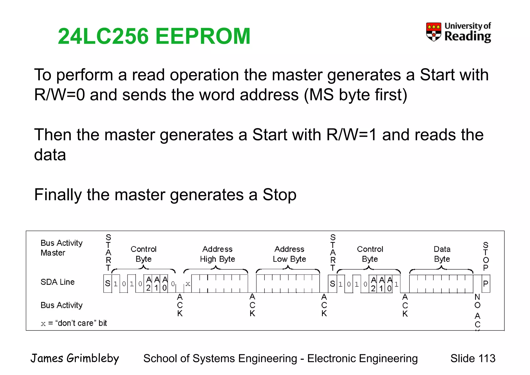
    24LC256 EEPROM To performa read operation the master generates a Start with 24LC256 EEPROM p p g R/W=0 and sends the word address (MS byte first) Then the master generates a Start with R/W=1 and reads the data Finally the master generates a Stop School of Systems Engineering - Electronic Engineering Slide 113James Grimbleby
  • 114.
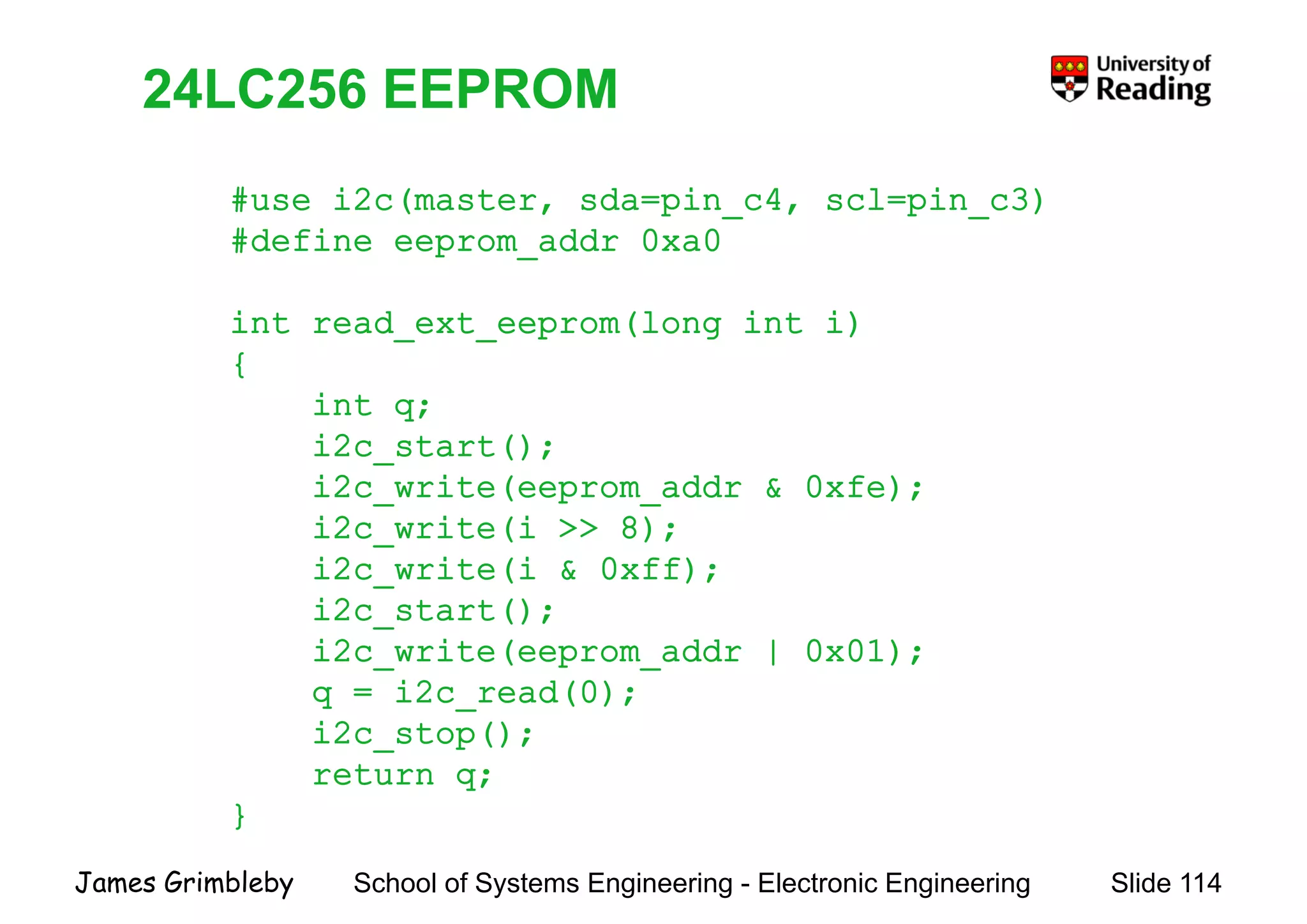
    24LC256 EEPROM #use i2c(master,sda=pin c4, scl=pin c3) 24LC256 EEPROM #use i2c(master, sda pin_c4, scl pin_c3) #define eeprom_addr 0xa0 i d (l i i)int read_ext_eeprom(long int i) { int q;int q; i2c_start(); i2c_write(eeprom_addr & 0xfe); i2 i (i 8)i2c_write(i >> 8); i2c_write(i & 0xff); i2c start();i2c_start(); i2c_write(eeprom_addr | 0x01); q = i2c_read(0); i2 ()i2c_stop(); return q; } School of Systems Engineering - Electronic Engineering Slide 114James Grimbleby }
  • 115.
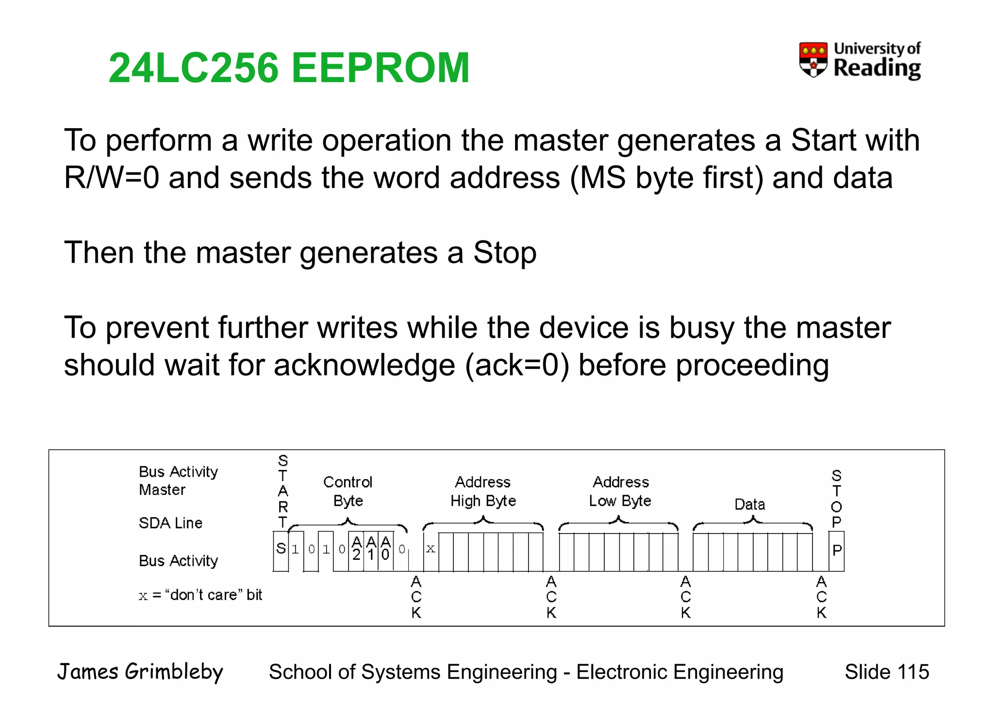
    24LC256 EEPROM To performa write operation the master generates a Start with 24LC256 EEPROM p p g R/W=0 and sends the word address (MS byte first) and data Then the master generates a Stop To prevent further writes while the device is busy the master should wait for acknowledge (ack=0) before proceeding School of Systems Engineering - Electronic Engineering Slide 115James Grimbleby
  • 116.
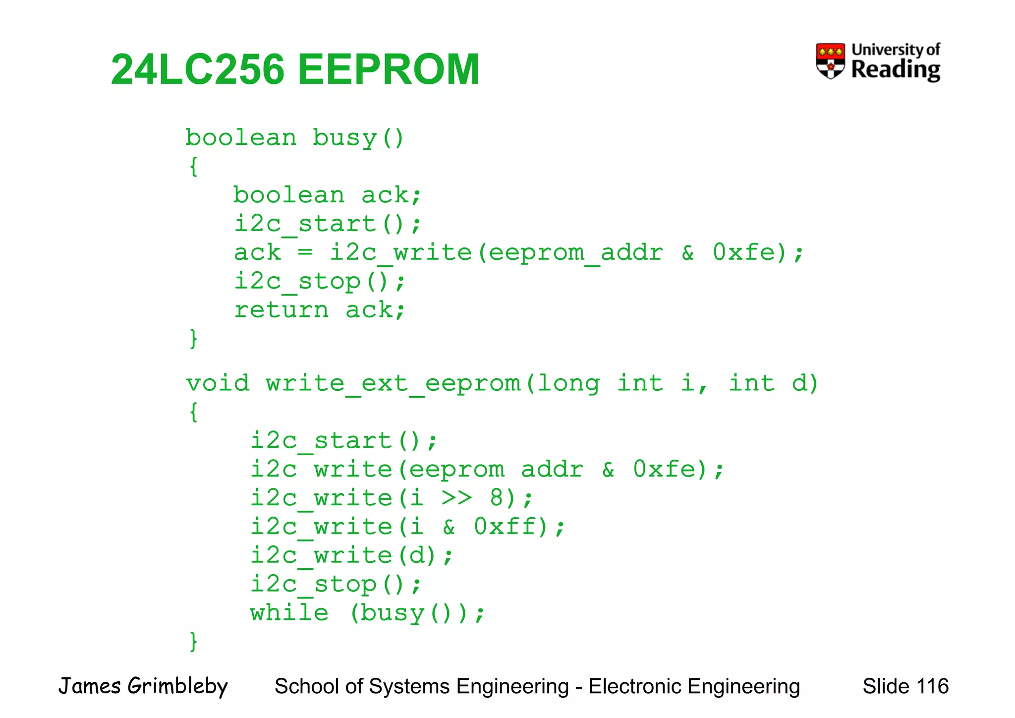
    24LC256 EEPROM boolean busy() { 24LC256EEPROM { boolean ack; i2c_start(); k i i ( dd f )ack = i2c_write(eeprom_addr & 0xfe); i2c_stop(); return ack;; } void write_ext_eeprom(long int i, int d) { i2c_start(); i2c_write(eeprom_addr & 0xfe);_ ( p _ ); i2c_write(i >> 8); i2c_write(i & 0xff); i2c write(d);i2c_write(d); i2c_stop(); while (busy()); } School of Systems Engineering - Electronic Engineering Slide 116James Grimbleby }
  • 117.
    Programming PIC MicrocontrollersProgrammingPIC Microcontrollers © J. B. Grimbleby, 21 October 2008 School of Systems Engineering - Electronic Engineering Slide 117James Grimbleby