Download to read offline
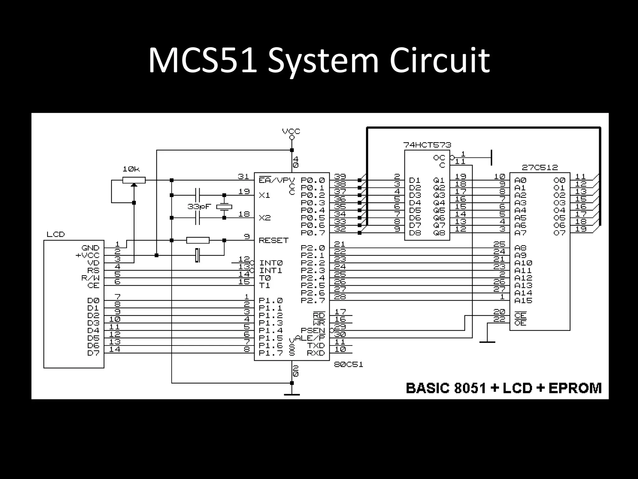
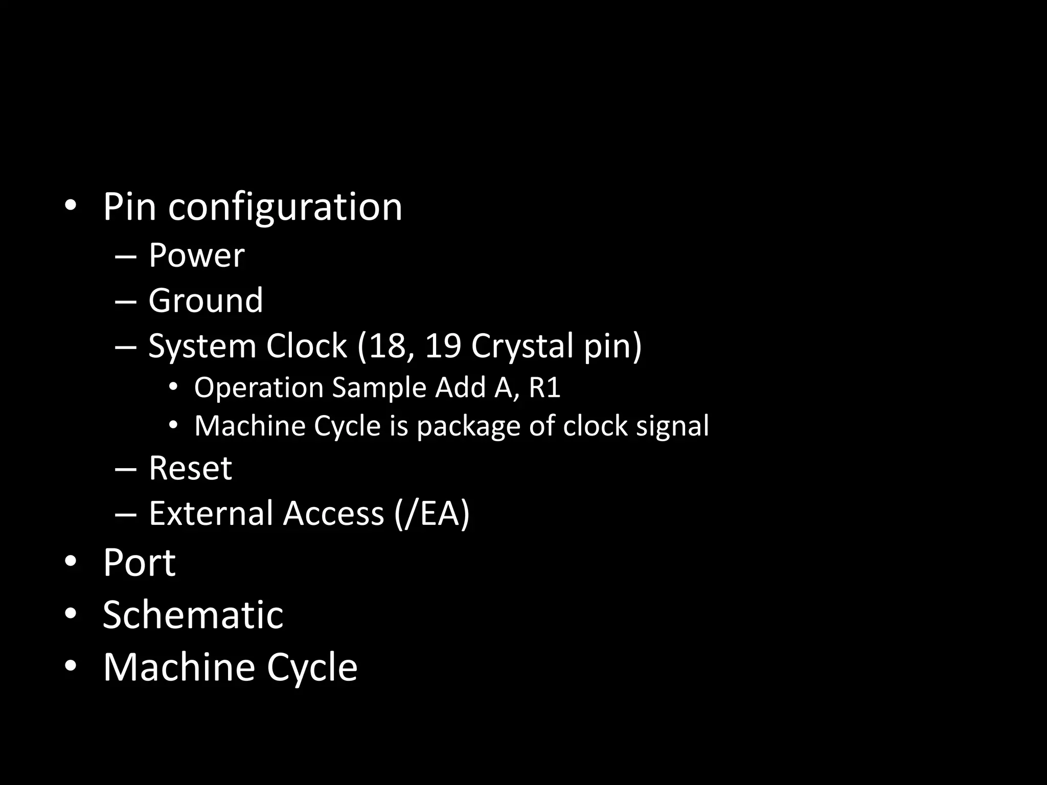


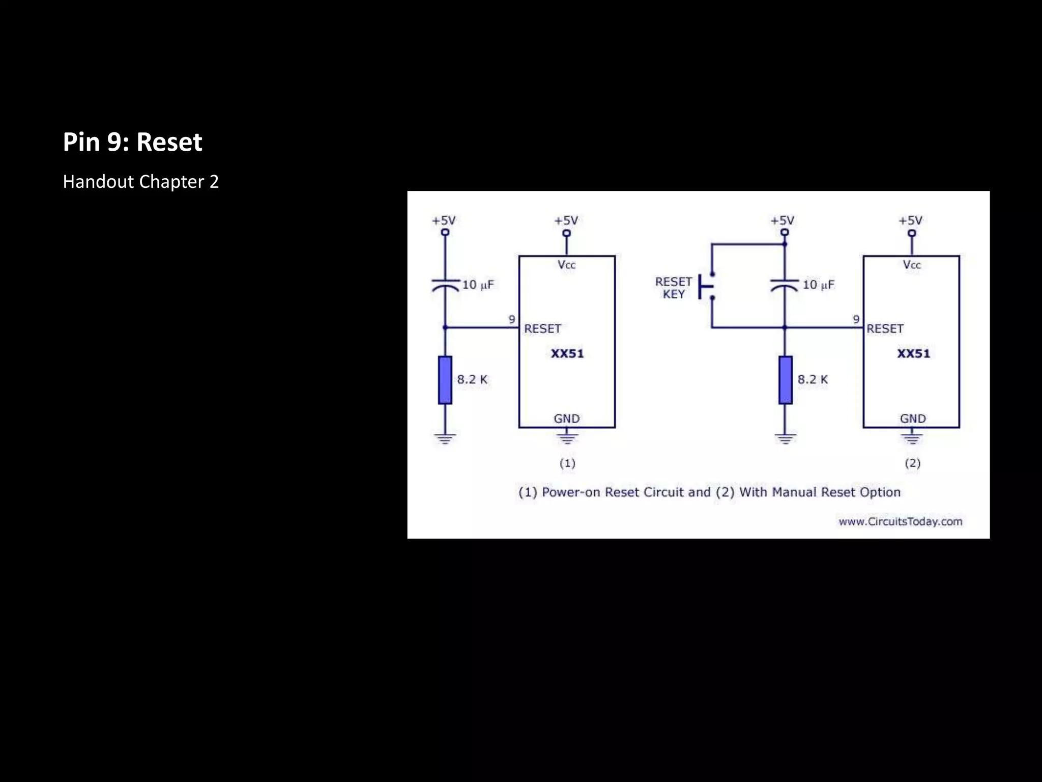


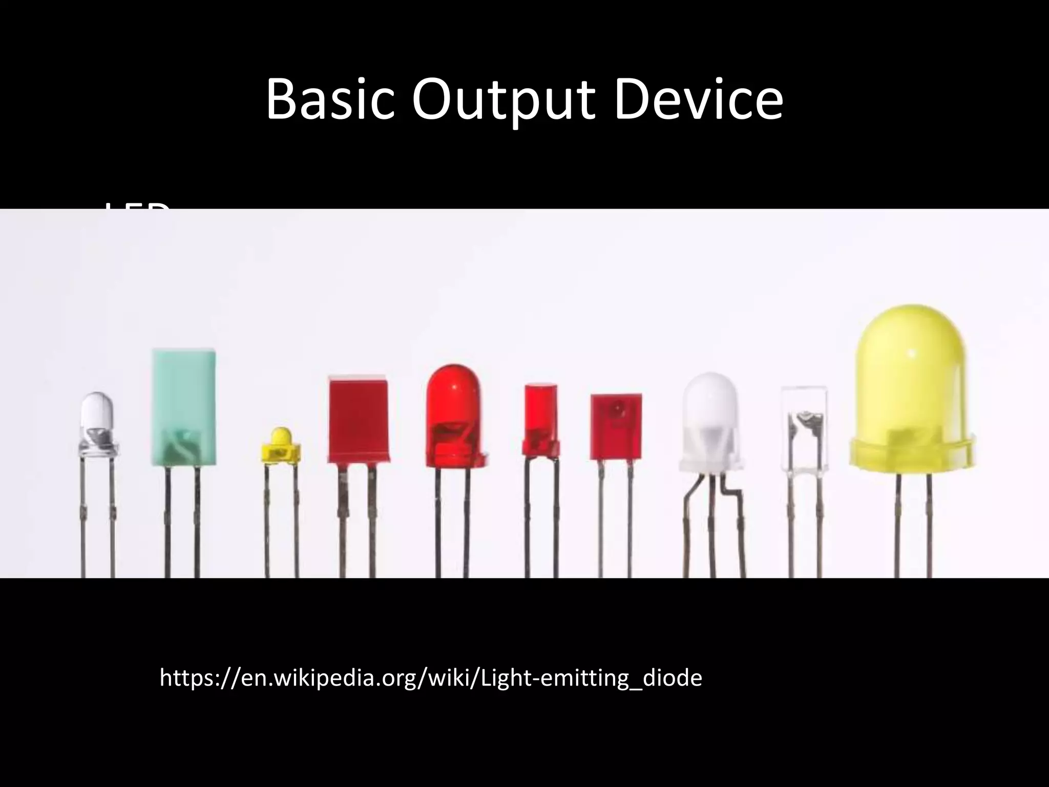
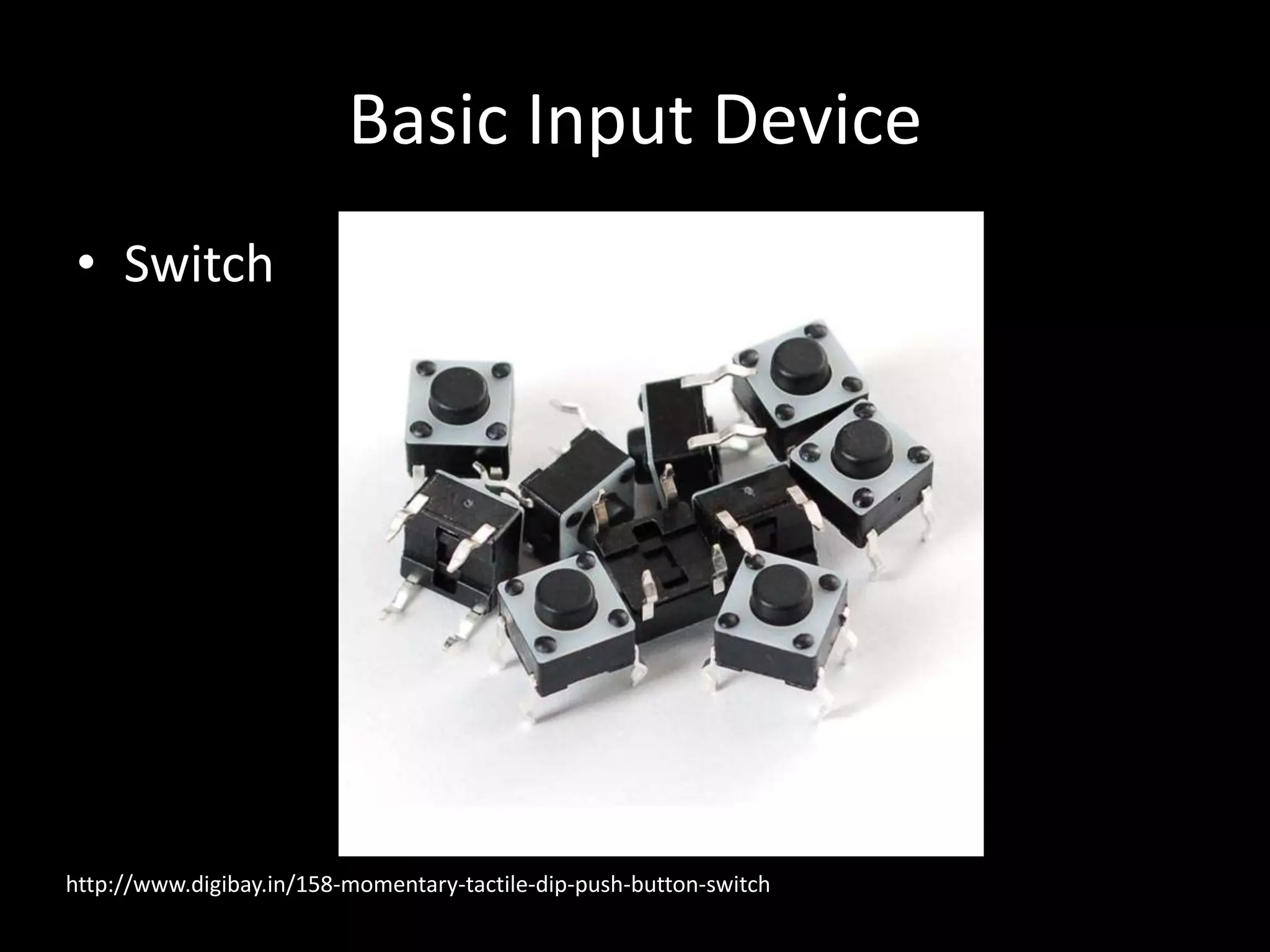


This document discusses the circuit and operation of the MCS51 microcontroller system. It describes the pin configuration including power, ground, crystal oscillator, reset and external access pins. It also covers the machine cycle, ports, input and output devices like LEDs and switches. Finally, it provides the homework assignment to draw a schematic of an MCS51 system circuit with a reset switch, 8 LED display and 4 push button switches identifying all component IDs, pin numbers, names and values.