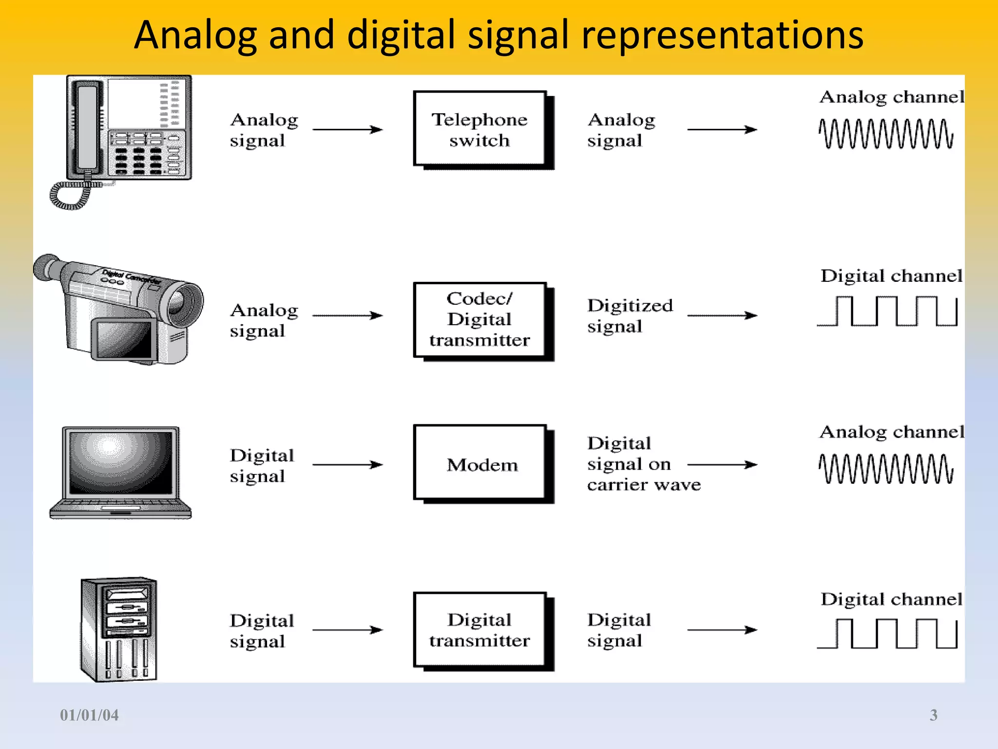
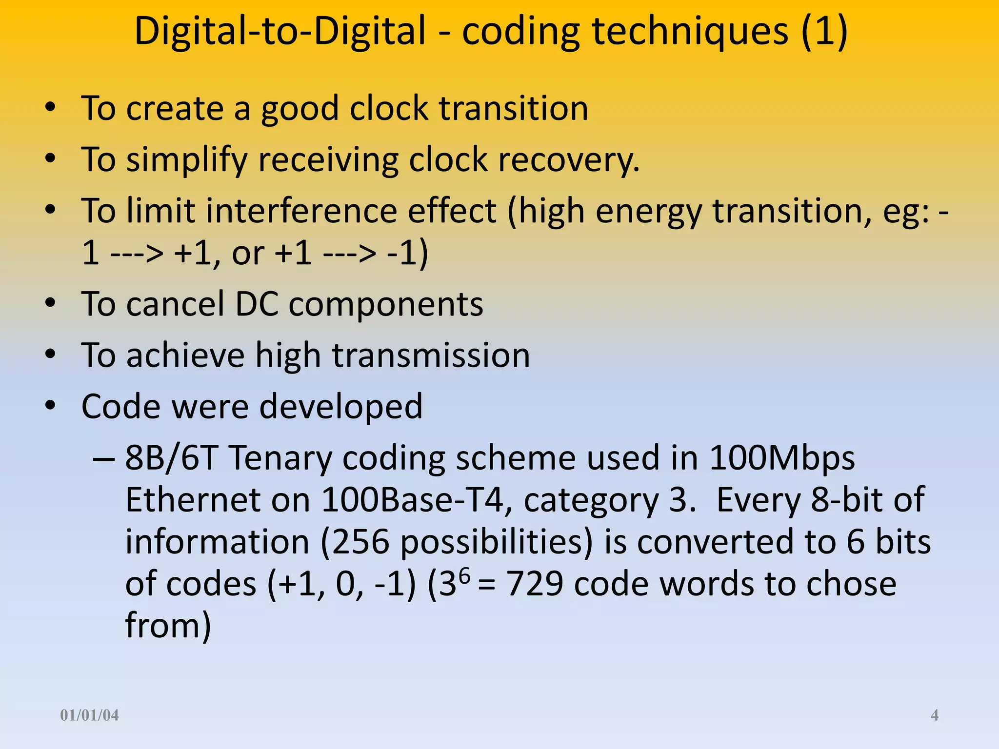
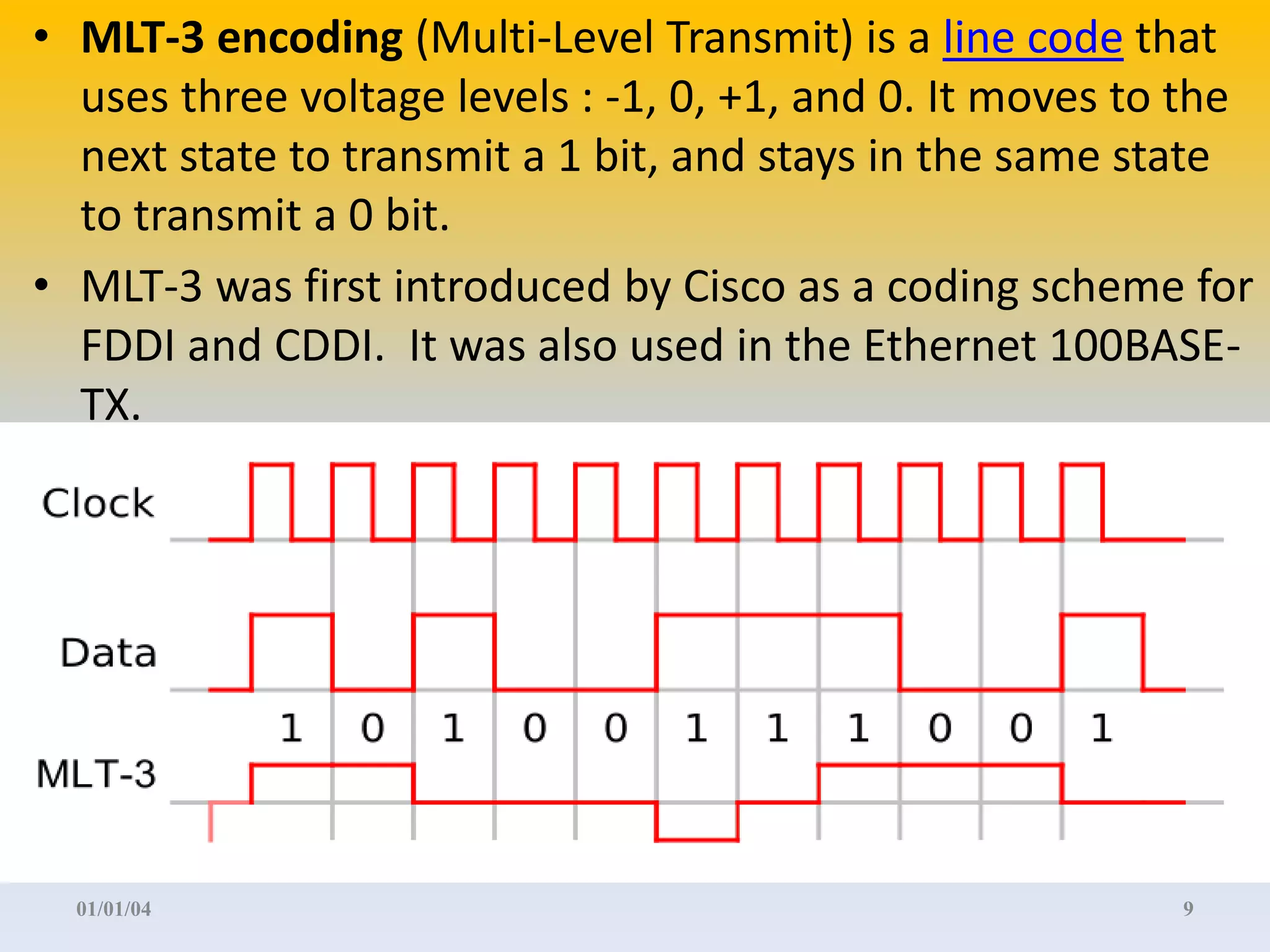
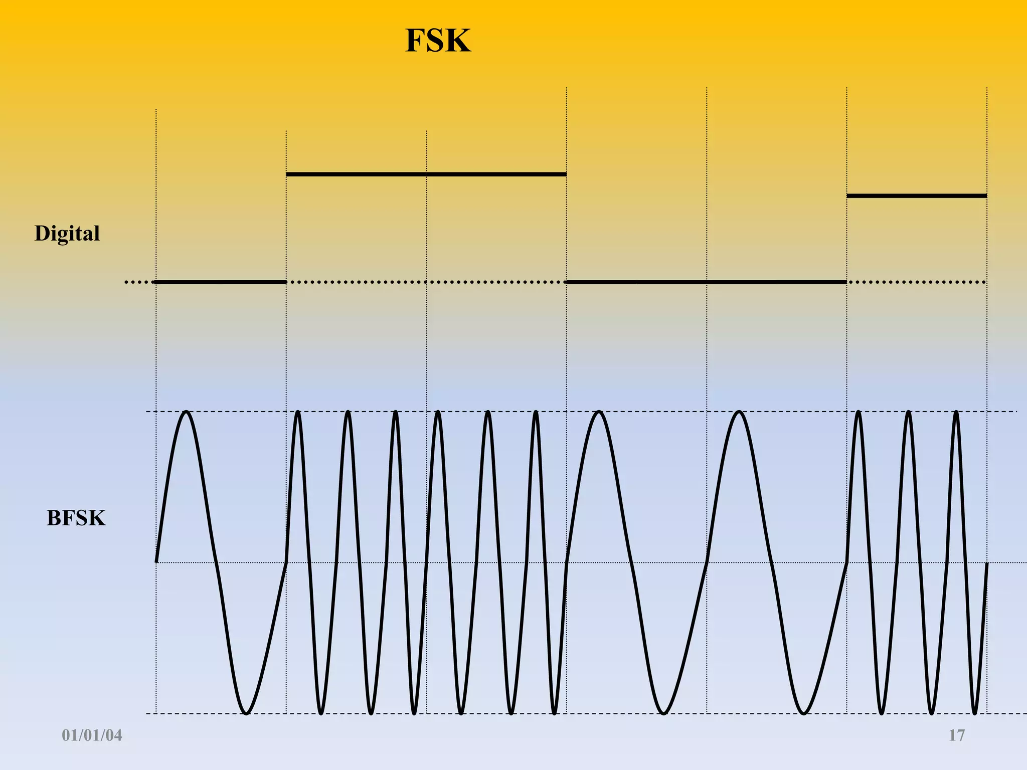
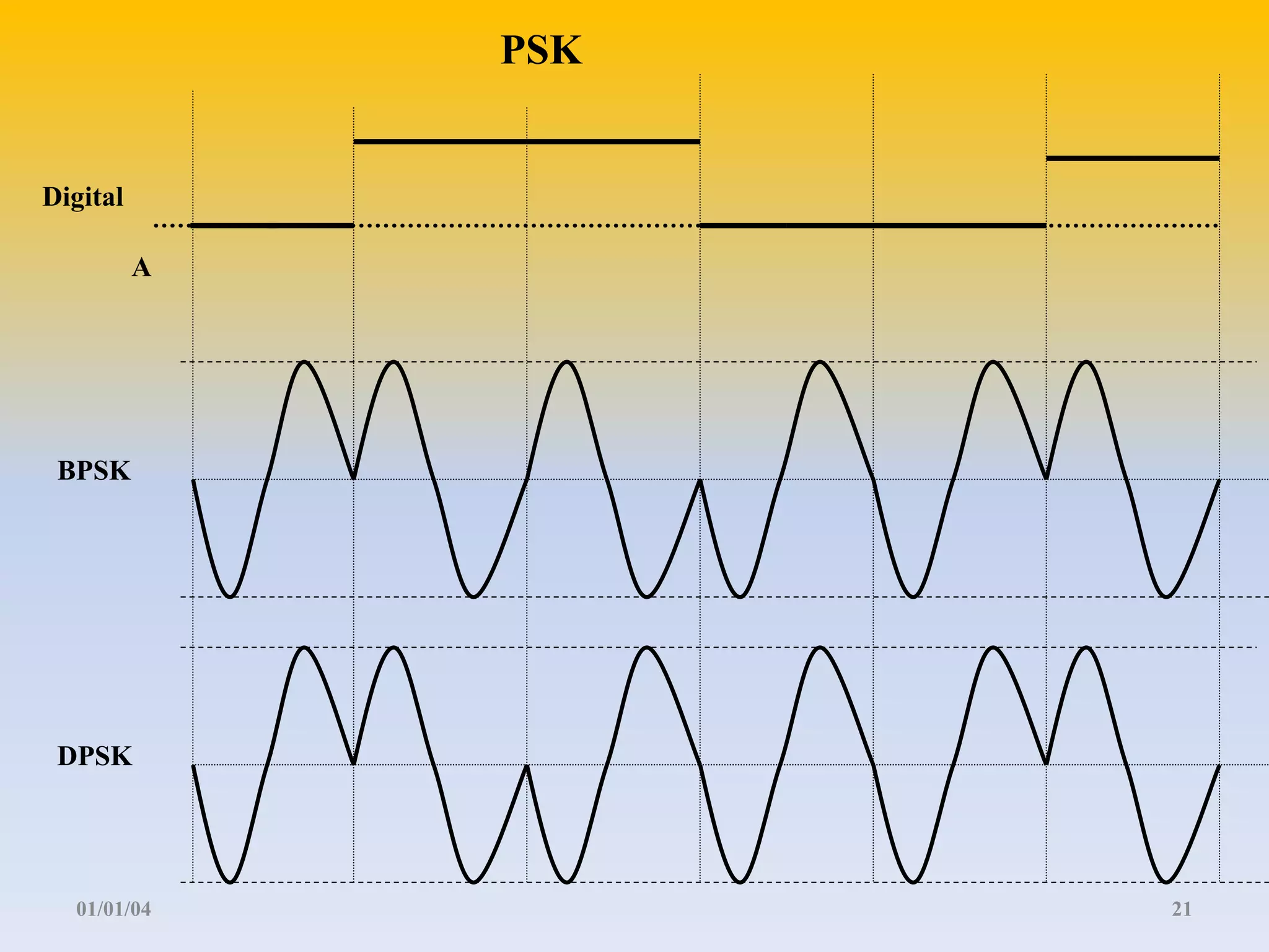
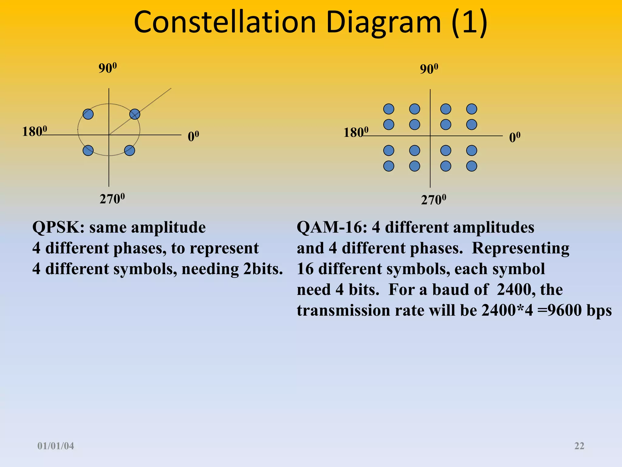
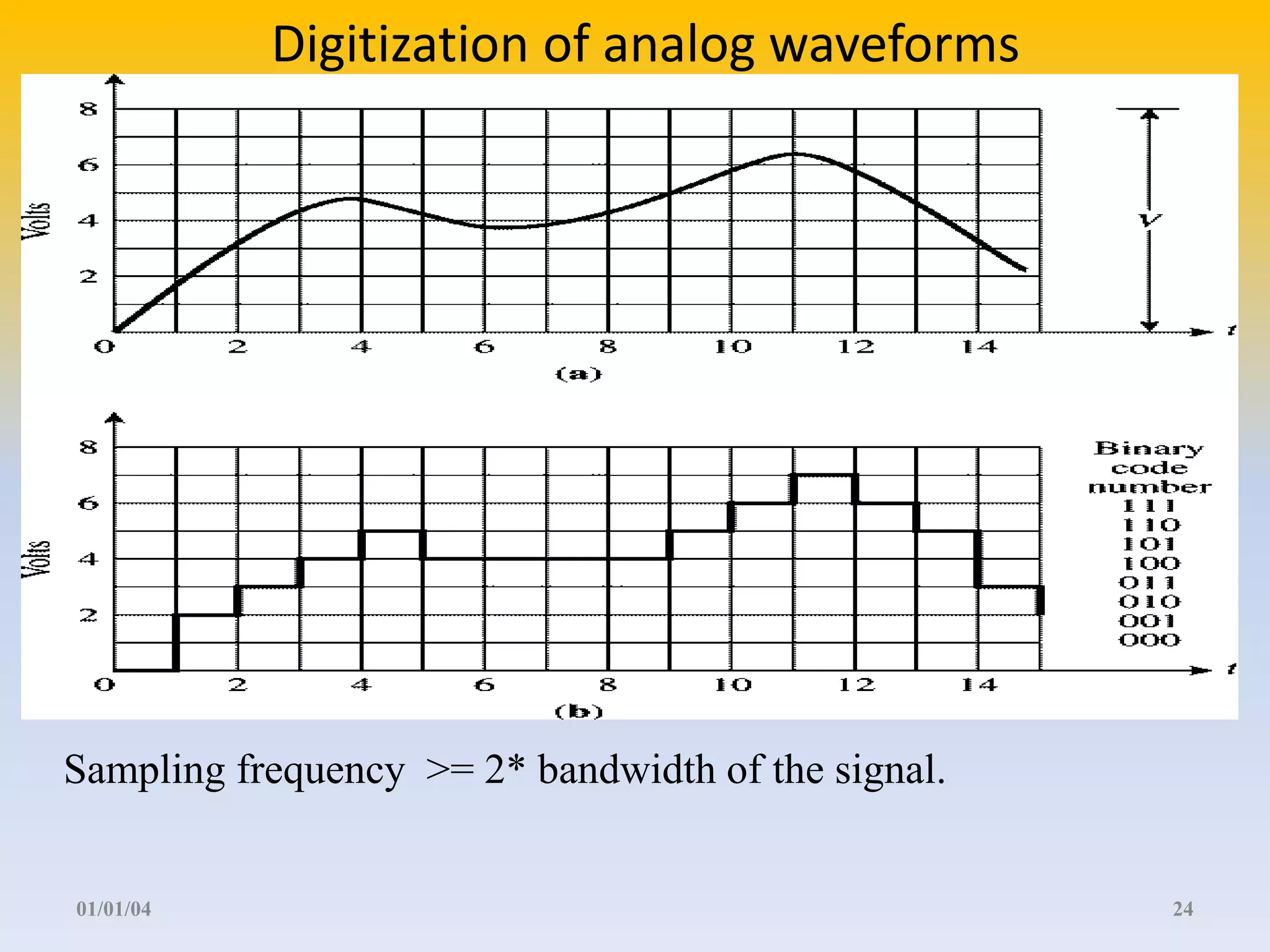
Lecture 2 Communication basics. (2 hours) 01/09/2012 1
Contents Further readings: Behrouz, Chapters 3, 4, 5, 7 (section 7.1), 10 • Modulation and encoding Techniques – Digital-to-Digital – Digital-to-Analog ( for wireless) – Analog-to-Digital 01/01/04 2
Analog and digital signal representations 01/01/04 3
Digital-to-Digital - coding techniques (1) • To create a good clock transition • To simplify receiving clock recovery. • To limit interference effect (high energy transition, eg: - 1 ---> +1, or +1 ---> -1) • To cancel DC components • To achieve high transmission • Code were developed – 8B/6T Tenary coding scheme used in 100Mbps Ethernet on 100Base-T4, category 3. Every 8-bit of information (256 possibilities) is converted to 6 bits of codes (+1, 0, -1) (36 = 729 code words to chose from) 01/01/04 4
Digital-to-Digital - Non-return to zero • NRZ-L used for terminals and other devices. • If the digital input is level 0, produce an output of positive voltage (level +v), for the duration of the bit. • If the digital input is level 1, produce an output of negative voltage (level -v), for the duration of the bit. • NRZI (also called differential encoding)used for magnetic recording. • If the next level digital input is 0, stay on the same level (no transition). • If the next level is 1, make a change to the opposite ( +/-) of the the current level • Simple/ low frequency response, but has dc component, lack of synchronization (long zeros), no good for transmission. 01/01/04 5
Digital input, base NRZ-L NRZI 01/01/04 6
Digital-to-Digital - Multilevel Binary • Solves the NRZ problems: No dc components (alternating 1 and 0 pulses), Low bandwidth compare to NRZ. But require more power to differentiate between 3 - levels, and the bit rate > NRZ. Used for ISDN for low data rate transmission. • Alternate Mark Inversion (AMI): • If the level of the digital input is 0, the output line is zero. • If the level of the digital input is 1, the output signal alternates between levels (+v) and (-v). There is no loss of synchronization for strings of 1’s. • Pseudo-Tenary: It is the opposite of AMI. • If the level of the digital input is 1, the output line is zero. • If the level of the digital input is 0, the output signal alternates between levels (+v) and (-v). There is no loss of synchronization for strings of 0’s. 01/01/04 7
Digital input, base AMI Pseudo-Tenary 01/01/04 8
• MLT-3 encoding (Multi-Level Transmit) is a line code that uses three voltage levels : -1, 0, +1, and 0. It moves to the next state to transmit a 1 bit, and stays in the same state to transmit a 0 bit. • MLT-3 was first introduced by Cisco as a coding scheme for FDDI and CDDI. It was also used in the Ethernet 100BASE-TX. 01/01/04 9
Digital-to-Digital - Bi-Phase • No dc component. Less interference. Easy to detect error, many transitions. However, the modulation rate is twice the bit rate. The signal is self-clocked. • Used in LAN CSMA/CD (802.3), Token ring (802.5) with STP, up to 10Mbps. Not used in WAN require high signaling rate. • Manchester Encoding: • In the middle of any bit for the input digital signal, there is a transition – • For 0, the transition is from level high to low. (or vise versa, keep consistency) • For 1, the transition is from level low to high. (or vise versa, keep consistency) • The changes at the beginning of the bits match the changes of the next middle. • Differential Manchester Encoding: If the next level in the input digital signal is 0 there is a transition – the output signal goes to the opposite level. If the next level in the input signal is 1 there is no transition at the beginning of a bit. There is always a transition – to the opposite level- in the middle of the bit for self-clocking.) 01/01/04 10
Digital input, base Manchester Differential Manchester 01/01/04 11
Digital-to-Digital - coding techniques (2) • For instance – 00000000 ----> 0 +1 0 -1 +1 0 – 00000001 ----> 0 -1 +1 0 -1 0 – 00000010 -----> 0 -1 0 1 -1 0 • 4B/5B code for full duplex 100Base-Tx category 5 and 100Base-Fx Ethernet. Every 4 bits are converted into a 5 bits binary code. The remaining 16 codes are used for frames boundaries • 8B/10B code (Fiber Channel Code) developed by IBM and licensed to 1Gbps Ethernet, for full duplex. The rules for choosing a code word amount 1024, no code word should have more than 4 identical bits in a row, no code may have more than 6 (0’s) or 6 (1’s) . 01/01/04 12
Digital-To-Analog - modulation • Uses public telephone line, transmitting voice frequency in the range 300 to 3400 HZ. Utilize modems. • Amplitude-shift keying (ASK) modulation • Frequency-shift Keying (FSK) modulation – Binary FSK (BFSK) – Multiple FSK (MFSK) • Phase-shift Keying (PSK) modulation – Binary PSK – Differential PSK (DPSK) – Multiple Level PSK • Quadratic AM and PSK: combination of ASK and ASK 01/01/04 13
ASK • Used on voice-grade lines < 1200bps. • Used in some optical fiber. • Used in Infrared wireless LAN, intensity modulation. • Inefficient. • ASK ( Amplitude Shift Keying) works as : – Binary 1 is transmitted by a sine wave of amplitude A1 cos(2 f t). – Binary 0 is transmitted by a sine wave of amplitude A2 cos(2 f t), Most implementations uses A2 as 0. 01/01/04 14
ASK Digital ASK A -A 01/01/04 15
FSK • Sender / Receiver may use different frequencies to allow full-duplex transmission on the same channel, Modems 1070, 1270, 2025, 2225 Hz. • Less susceptible to errors than ASK. • Can be used for higher frequencies (3-30MHz), radio transmission and LANs. • Can support Multiple levels MFSK. • BFSK: ( Binary Frequency Shift Keying) – Binary 1 is transmitted as A cos(2 f1 t). – Binary 0 is transmitted as A cos(2 f2 t). 01/01/04 16
FSK Digital BFSK 01/01/04 17
MFSK • MFSK: S t A f t i M i i ( )  cos(2 ) 1  – Can support Multiple levels MFSK. – Where – fi = fc +(2i-1-M)fd – fc is the carrier frequency – fd is the difference frequency between two consecutive ones – M the number of different signals M = 2L, L is the number of bits in a symbol. – The total bandwidth is wd = 2(M-1)fd – The bit rate is 1/T and the signal element is held for a period of Ts = LT 01/01/04 18
Example MFSK • M=4 that each different signal represent two bits (n=2). • With fc = 250KHz and fd = 25KHz we have the following frequencies: • f1 = 175KHz, f2 = 225KHz, f3 = 275KHz, f4 = 325KHz • The bandwidth is Wd = 2*(4-1)*25 = 150KHz, the bit rate is 50Kbps. 01 11 00 11 11 01 10 00 00 11 T Ts 325 275 225 175 Wd 01/01/04 19
PSK • BPSK: ( Binary Phase Shift keying) – for the binary 1, produce the sine wave A cos(2 f t). – for the binary 0, produce a sine wave A cos(2 f t + 180) = - A cos(2 f t). • DPSK: ( Differential PSK) – Avoid using accurate local oscillator at the receiver. – 0 -> send a signal similar to the previous one. – 1->send a signal with phase shift to the previous one. • MPSK: – QPSK Quadratic PSK uses phase shift of multiples of /4, for more details see reading list. 01/01/04 20
PSK Digital A BPSK DPSK 01/01/04 21
Constellation Diagram (1) 900 180 00 0 2700 900 180 00 0 2700 QPSK: same amplitude 4 different phases, to represent 4 different symbols, needing 2bits. QAM-16: 4 different amplitudes and 4 different phases. Representing 16 different symbols, each symbol need 4 bits. For a baud of 2400, the transmission rate will be 2400*4 =9600 bps 01/01/04 22
Analog-to-Digital • Voice sent with digital transmission. • CODEC - Digitization. • Pulse Code Modulation PCM: signal is sampled into discrete levels and coded in binary them transmitted. • Delta modulation DM: improve on the complexity of PCM but modulating the differences in the signal. 01/01/04 23
Digitization of analog waveforms Sampling frequency >= 2* bandwidth of the signal. 01/01/04 24
Quiz 1. What is the difference between Digital to Analog and digital to digital modulations? 2. What is a DC component? 3. Where do we use analog to digital modulation? 4. Give an example for 4B/5B code. 5. What information does the constellation diagram give? 6. How does MFSK improve the bit rate over FSK? 01/01/04 25

Lecture 2 encoding

  • 1.
    Lecture 2 Communicationbasics. (2 hours) 01/09/2012 1
  • 2.
    Contents Further readings:Behrouz, Chapters 3, 4, 5, 7 (section 7.1), 10 • Modulation and encoding Techniques – Digital-to-Digital – Digital-to-Analog ( for wireless) – Analog-to-Digital 01/01/04 2
  • 3.
    Analog and digitalsignal representations 01/01/04 3
  • 4.
    Digital-to-Digital - codingtechniques (1) • To create a good clock transition • To simplify receiving clock recovery. • To limit interference effect (high energy transition, eg: - 1 ---> +1, or +1 ---> -1) • To cancel DC components • To achieve high transmission • Code were developed – 8B/6T Tenary coding scheme used in 100Mbps Ethernet on 100Base-T4, category 3. Every 8-bit of information (256 possibilities) is converted to 6 bits of codes (+1, 0, -1) (36 = 729 code words to chose from) 01/01/04 4
  • 5.
    Digital-to-Digital - Non-returnto zero • NRZ-L used for terminals and other devices. • If the digital input is level 0, produce an output of positive voltage (level +v), for the duration of the bit. • If the digital input is level 1, produce an output of negative voltage (level -v), for the duration of the bit. • NRZI (also called differential encoding)used for magnetic recording. • If the next level digital input is 0, stay on the same level (no transition). • If the next level is 1, make a change to the opposite ( +/-) of the the current level • Simple/ low frequency response, but has dc component, lack of synchronization (long zeros), no good for transmission. 01/01/04 5
  • 6.
    Digital input, base NRZ-L NRZI 01/01/04 6
  • 7.
    Digital-to-Digital - MultilevelBinary • Solves the NRZ problems: No dc components (alternating 1 and 0 pulses), Low bandwidth compare to NRZ. But require more power to differentiate between 3 - levels, and the bit rate > NRZ. Used for ISDN for low data rate transmission. • Alternate Mark Inversion (AMI): • If the level of the digital input is 0, the output line is zero. • If the level of the digital input is 1, the output signal alternates between levels (+v) and (-v). There is no loss of synchronization for strings of 1’s. • Pseudo-Tenary: It is the opposite of AMI. • If the level of the digital input is 1, the output line is zero. • If the level of the digital input is 0, the output signal alternates between levels (+v) and (-v). There is no loss of synchronization for strings of 0’s. 01/01/04 7
  • 8.
    Digital input, base AMI Pseudo-Tenary 01/01/04 8
  • 9.
    • MLT-3 encoding(Multi-Level Transmit) is a line code that uses three voltage levels : -1, 0, +1, and 0. It moves to the next state to transmit a 1 bit, and stays in the same state to transmit a 0 bit. • MLT-3 was first introduced by Cisco as a coding scheme for FDDI and CDDI. It was also used in the Ethernet 100BASE-TX. 01/01/04 9
  • 10.
    Digital-to-Digital - Bi-Phase • No dc component. Less interference. Easy to detect error, many transitions. However, the modulation rate is twice the bit rate. The signal is self-clocked. • Used in LAN CSMA/CD (802.3), Token ring (802.5) with STP, up to 10Mbps. Not used in WAN require high signaling rate. • Manchester Encoding: • In the middle of any bit for the input digital signal, there is a transition – • For 0, the transition is from level high to low. (or vise versa, keep consistency) • For 1, the transition is from level low to high. (or vise versa, keep consistency) • The changes at the beginning of the bits match the changes of the next middle. • Differential Manchester Encoding: If the next level in the input digital signal is 0 there is a transition – the output signal goes to the opposite level. If the next level in the input signal is 1 there is no transition at the beginning of a bit. There is always a transition – to the opposite level- in the middle of the bit for self-clocking.) 01/01/04 10
  • 11.
    Digital input, base Manchester Differential Manchester 01/01/04 11
  • 12.
    Digital-to-Digital - codingtechniques (2) • For instance – 00000000 ----> 0 +1 0 -1 +1 0 – 00000001 ----> 0 -1 +1 0 -1 0 – 00000010 -----> 0 -1 0 1 -1 0 • 4B/5B code for full duplex 100Base-Tx category 5 and 100Base-Fx Ethernet. Every 4 bits are converted into a 5 bits binary code. The remaining 16 codes are used for frames boundaries • 8B/10B code (Fiber Channel Code) developed by IBM and licensed to 1Gbps Ethernet, for full duplex. The rules for choosing a code word amount 1024, no code word should have more than 4 identical bits in a row, no code may have more than 6 (0’s) or 6 (1’s) . 01/01/04 12
  • 13.
    Digital-To-Analog - modulation • Uses public telephone line, transmitting voice frequency in the range 300 to 3400 HZ. Utilize modems. • Amplitude-shift keying (ASK) modulation • Frequency-shift Keying (FSK) modulation – Binary FSK (BFSK) – Multiple FSK (MFSK) • Phase-shift Keying (PSK) modulation – Binary PSK – Differential PSK (DPSK) – Multiple Level PSK • Quadratic AM and PSK: combination of ASK and ASK 01/01/04 13
  • 14.
    ASK • Usedon voice-grade lines < 1200bps. • Used in some optical fiber. • Used in Infrared wireless LAN, intensity modulation. • Inefficient. • ASK ( Amplitude Shift Keying) works as : – Binary 1 is transmitted by a sine wave of amplitude A1 cos(2 f t). – Binary 0 is transmitted by a sine wave of amplitude A2 cos(2 f t), Most implementations uses A2 as 0. 01/01/04 14
  • 15.
    ASK Digital ASK A -A 01/01/04 15
  • 16.
    FSK • Sender/ Receiver may use different frequencies to allow full-duplex transmission on the same channel, Modems 1070, 1270, 2025, 2225 Hz. • Less susceptible to errors than ASK. • Can be used for higher frequencies (3-30MHz), radio transmission and LANs. • Can support Multiple levels MFSK. • BFSK: ( Binary Frequency Shift Keying) – Binary 1 is transmitted as A cos(2 f1 t). – Binary 0 is transmitted as A cos(2 f2 t). 01/01/04 16
  • 17.
    FSK Digital BFSK 01/01/04 17
  • 18.
    MFSK • MFSK: S t A f t i M i i ( )  cos(2 ) 1  – Can support Multiple levels MFSK. – Where – fi = fc +(2i-1-M)fd – fc is the carrier frequency – fd is the difference frequency between two consecutive ones – M the number of different signals M = 2L, L is the number of bits in a symbol. – The total bandwidth is wd = 2(M-1)fd – The bit rate is 1/T and the signal element is held for a period of Ts = LT 01/01/04 18
  • 19.
    Example MFSK •M=4 that each different signal represent two bits (n=2). • With fc = 250KHz and fd = 25KHz we have the following frequencies: • f1 = 175KHz, f2 = 225KHz, f3 = 275KHz, f4 = 325KHz • The bandwidth is Wd = 2*(4-1)*25 = 150KHz, the bit rate is 50Kbps. 01 11 00 11 11 01 10 00 00 11 T Ts 325 275 225 175 Wd 01/01/04 19
  • 20.
    PSK • BPSK:( Binary Phase Shift keying) – for the binary 1, produce the sine wave A cos(2 f t). – for the binary 0, produce a sine wave A cos(2 f t + 180) = - A cos(2 f t). • DPSK: ( Differential PSK) – Avoid using accurate local oscillator at the receiver. – 0 -> send a signal similar to the previous one. – 1->send a signal with phase shift to the previous one. • MPSK: – QPSK Quadratic PSK uses phase shift of multiples of /4, for more details see reading list. 01/01/04 20
  • 21.
    PSK Digital A BPSK DPSK 01/01/04 21
  • 22.
    Constellation Diagram (1) 900 180 00 0 2700 900 180 00 0 2700 QPSK: same amplitude 4 different phases, to represent 4 different symbols, needing 2bits. QAM-16: 4 different amplitudes and 4 different phases. Representing 16 different symbols, each symbol need 4 bits. For a baud of 2400, the transmission rate will be 2400*4 =9600 bps 01/01/04 22
  • 23.
    Analog-to-Digital • Voicesent with digital transmission. • CODEC - Digitization. • Pulse Code Modulation PCM: signal is sampled into discrete levels and coded in binary them transmitted. • Delta modulation DM: improve on the complexity of PCM but modulating the differences in the signal. 01/01/04 23
  • 24.
    Digitization of analogwaveforms Sampling frequency >= 2* bandwidth of the signal. 01/01/04 24
  • 25.
    Quiz 1. Whatis the difference between Digital to Analog and digital to digital modulations? 2. What is a DC component? 3. Where do we use analog to digital modulation? 4. Give an example for 4B/5B code. 5. What information does the constellation diagram give? 6. How does MFSK improve the bit rate over FSK? 01/01/04 25