Downloaded 130 times


This document discusses digital data transmission, line coding, and pulse shaping. It covers several key topics: - Digital data transmission involves converting analog signals like voice or images to binary digits for transmission and reconverting them at the receiving end. This allows for clearer, faster transmission using less bandwidth. - There are two main transmission modes: parallel transmits multiple bits at once for higher speed, while serial transmits one bit at a time to reduce costs. Conversion is needed between parallel and serial interfaces. - Line coding converts digital bits to voltage levels for transmission. Common schemes include NRZ, RZ, Manchester, AMI, and pseudoternary. - Pulse shaping filters transmitted pulses to limit
Introduction to digital data transmission, converting information into binary for clearer communication.
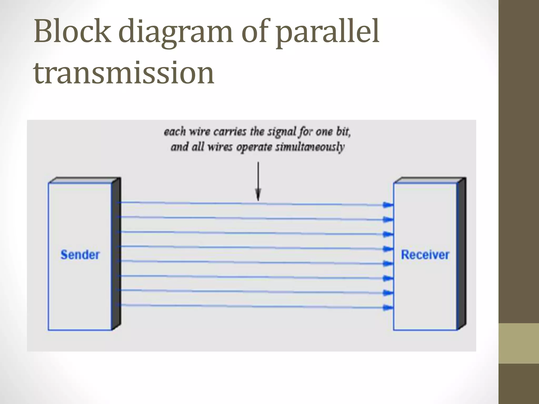
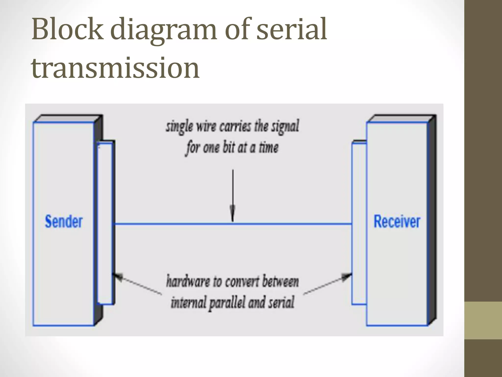
Explains parallel and serial transmission, highlighting their advantages, block diagrams showing data flow.
Describes asynchronous, synchronous, and isochronous transmissions, noting their operational differences.
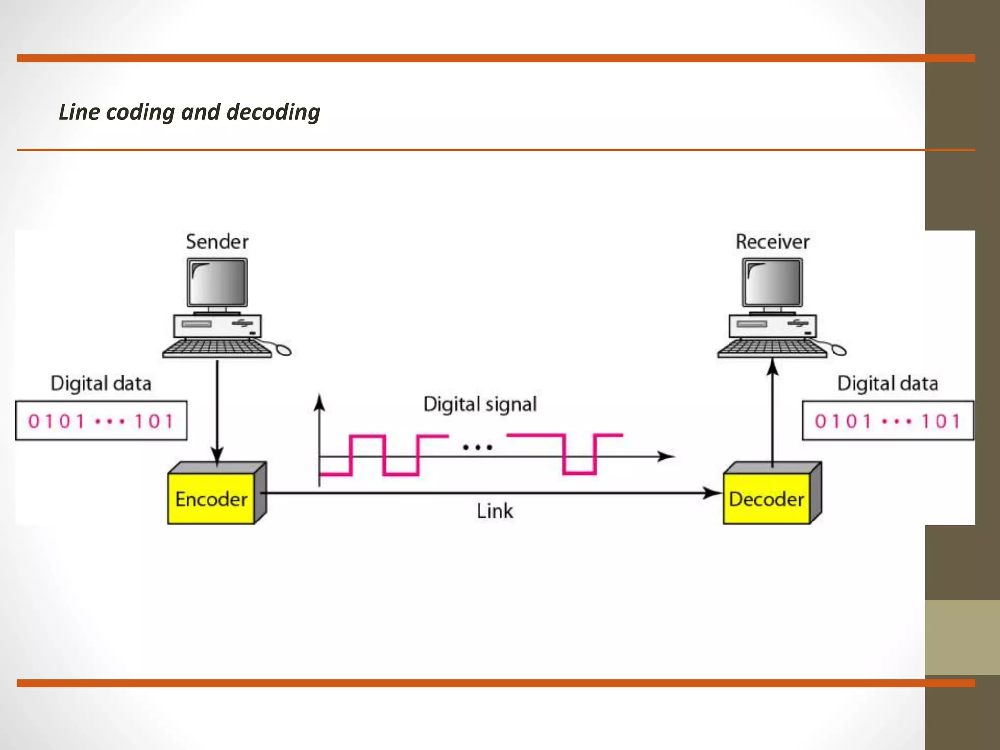
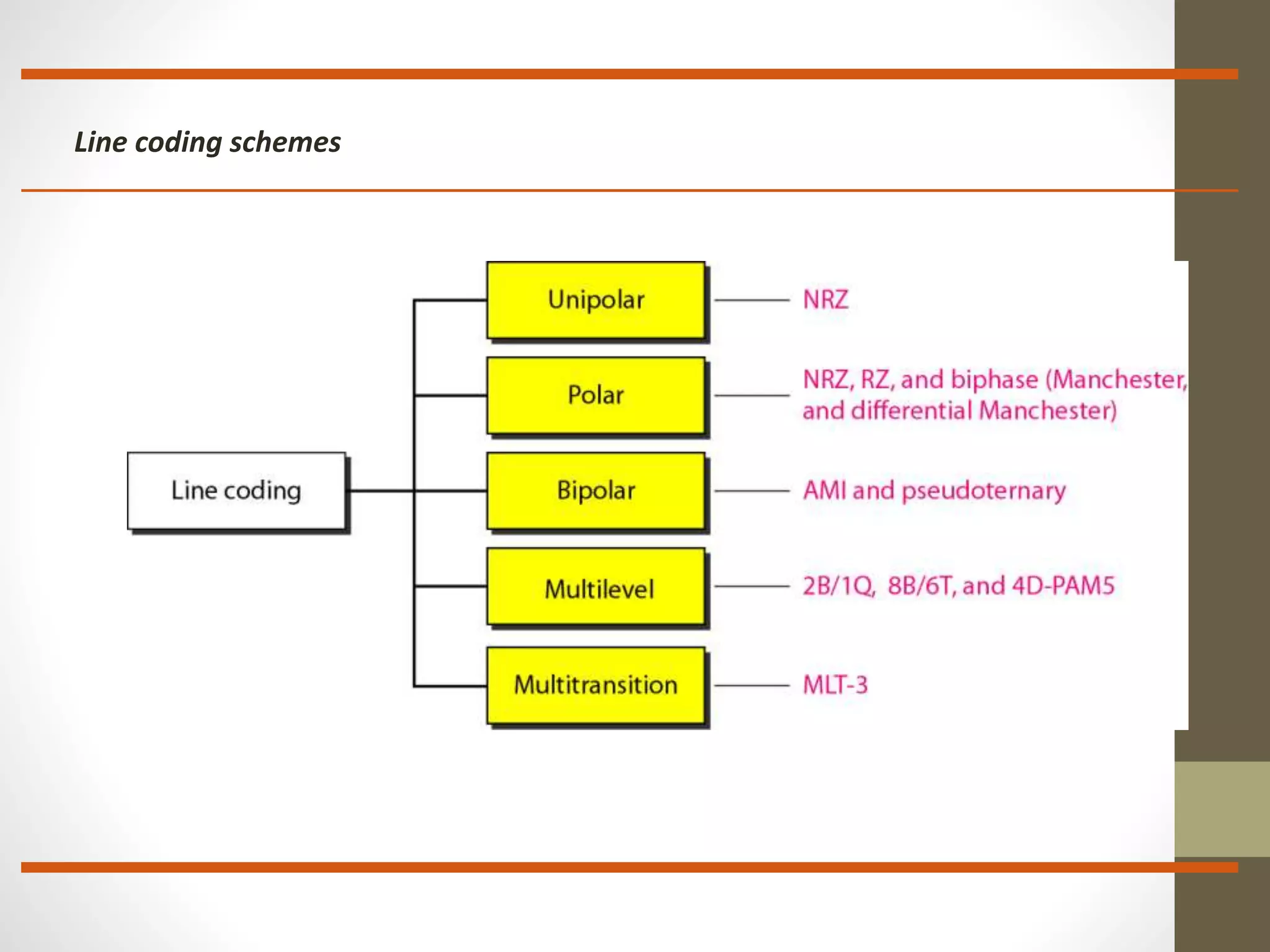
Introduction to line coding, converting digital data into signal sequences for transmission.
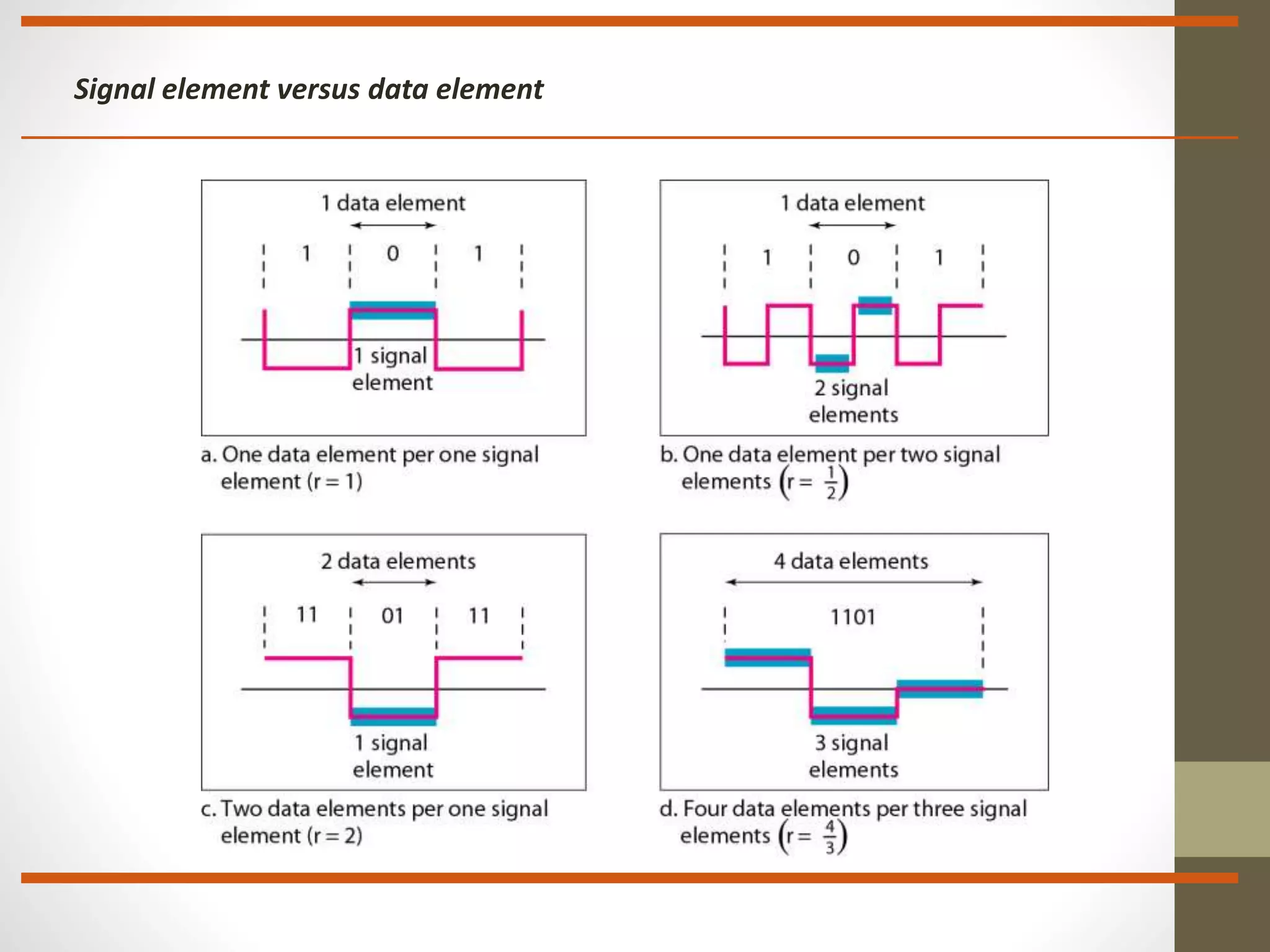
Discusses data rate vs signal rate and the goal of maximizing data transmission efficiency.
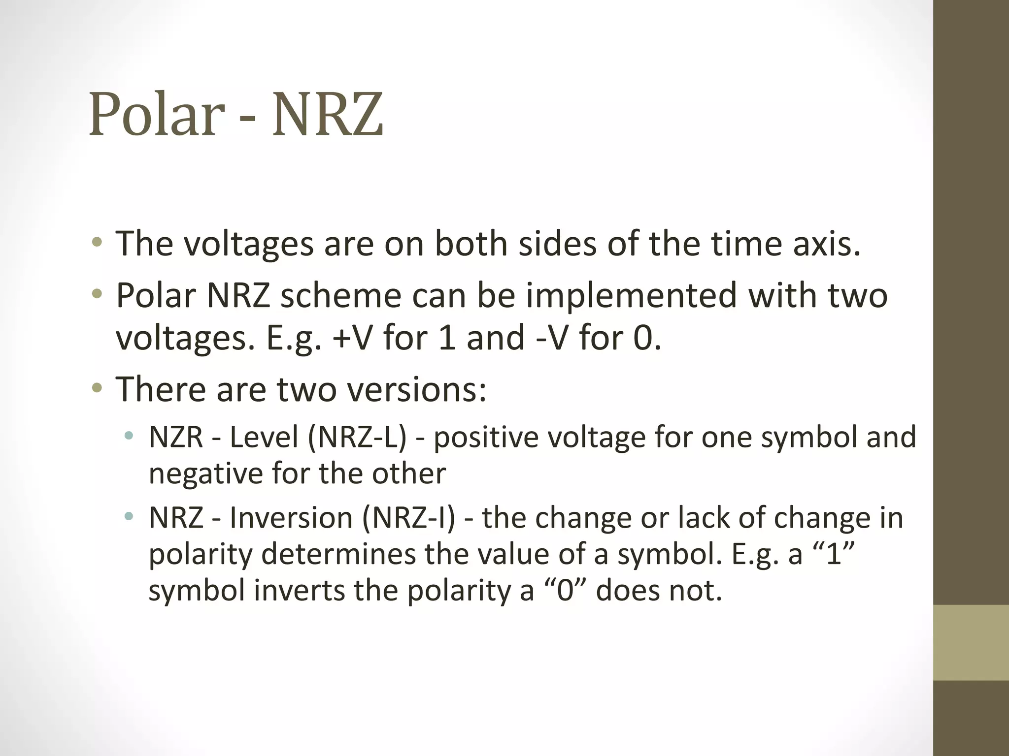
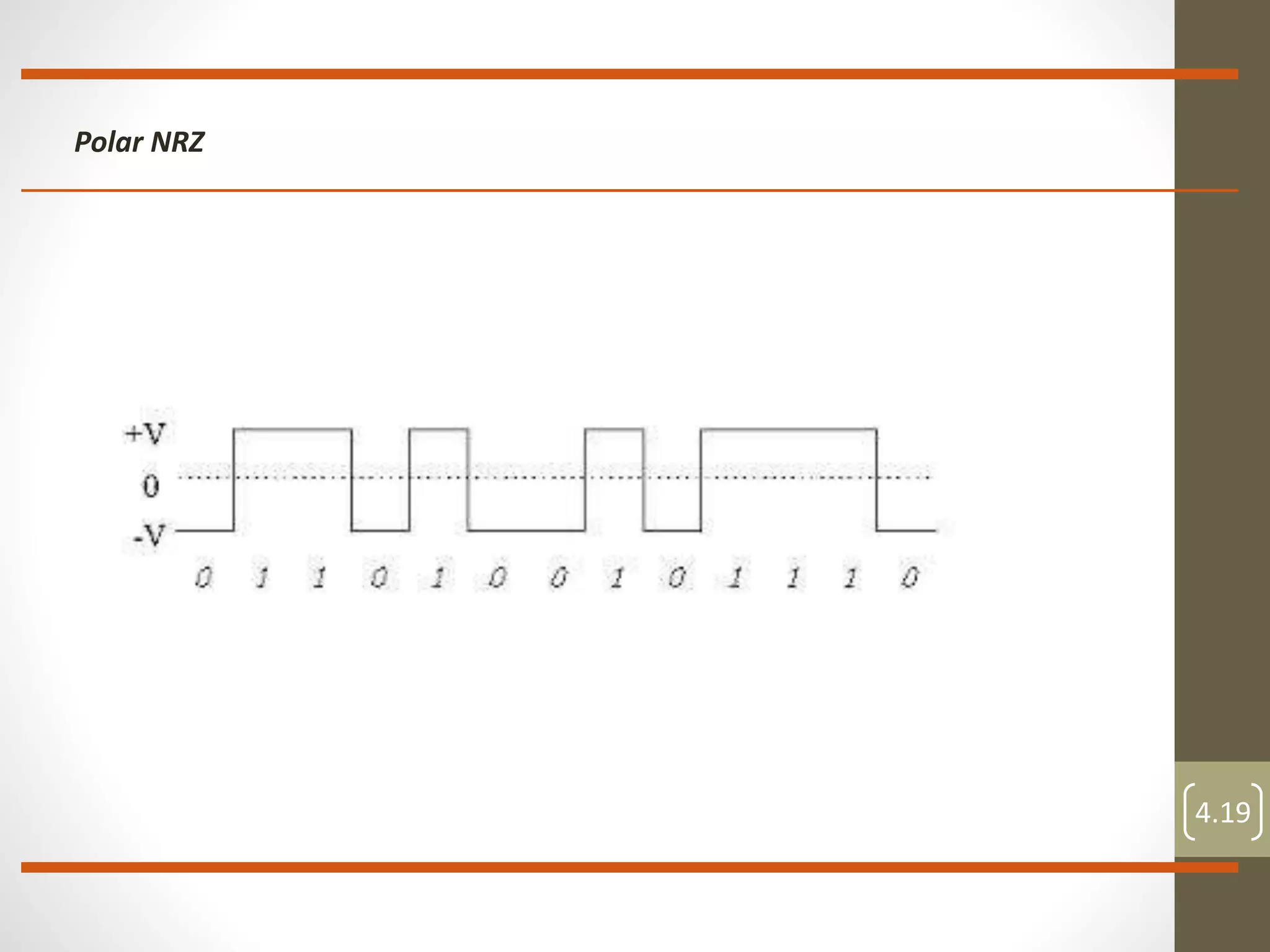
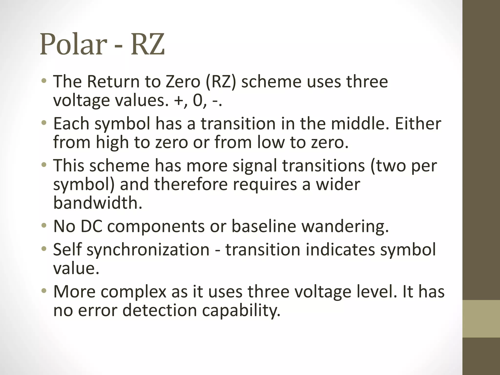
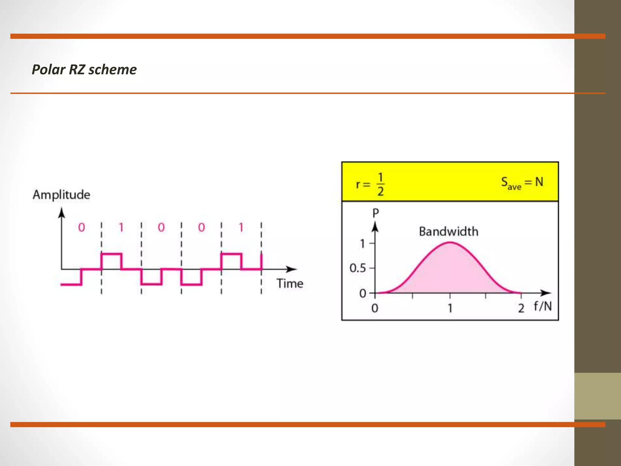
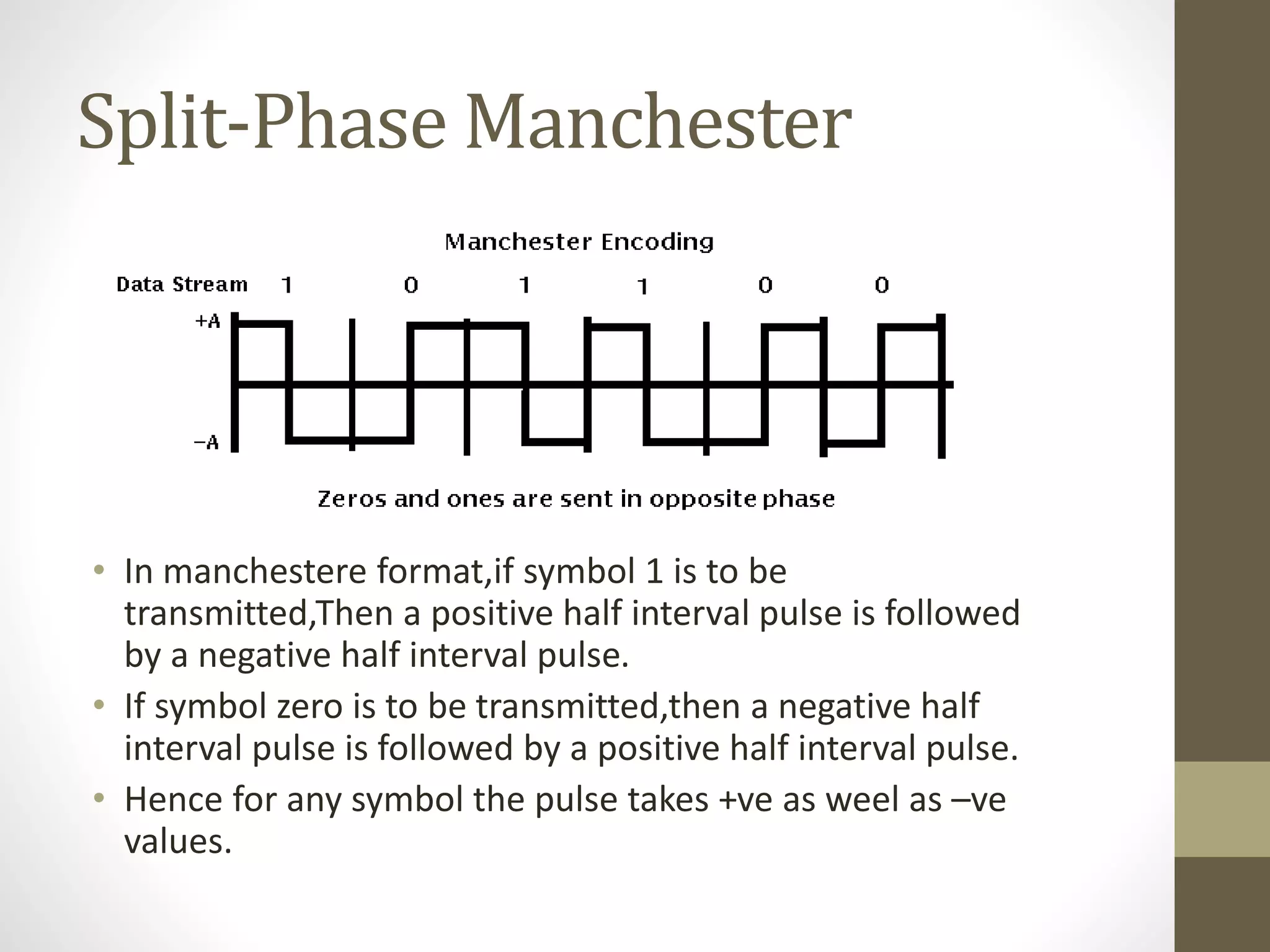
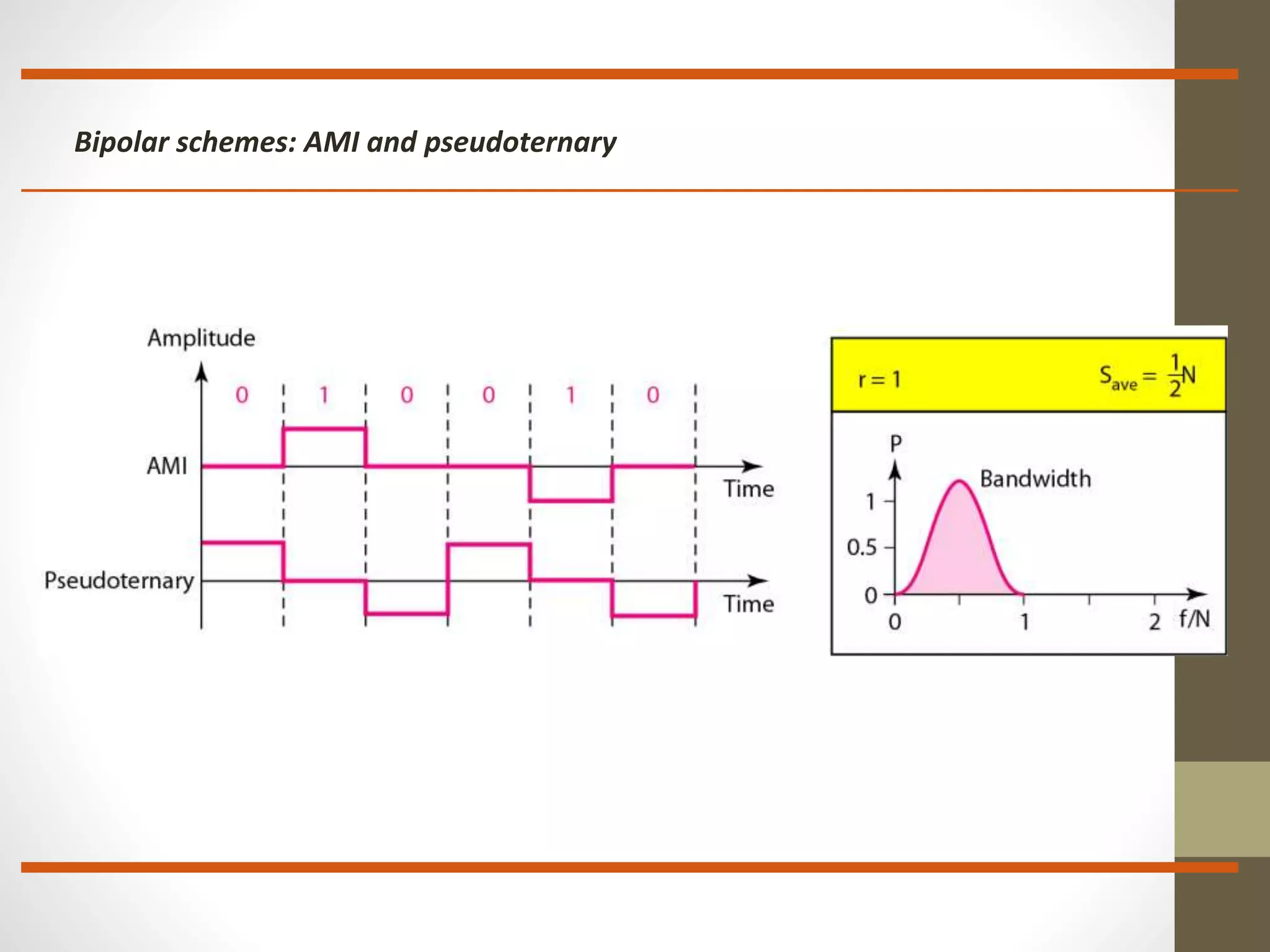
Various line coding schemes like Unipolar, Polar, and Bipolar, their characteristics, and implications.
Process of pulse shaping in telecommunications to improve bandwidth efficiency and reduce interference.
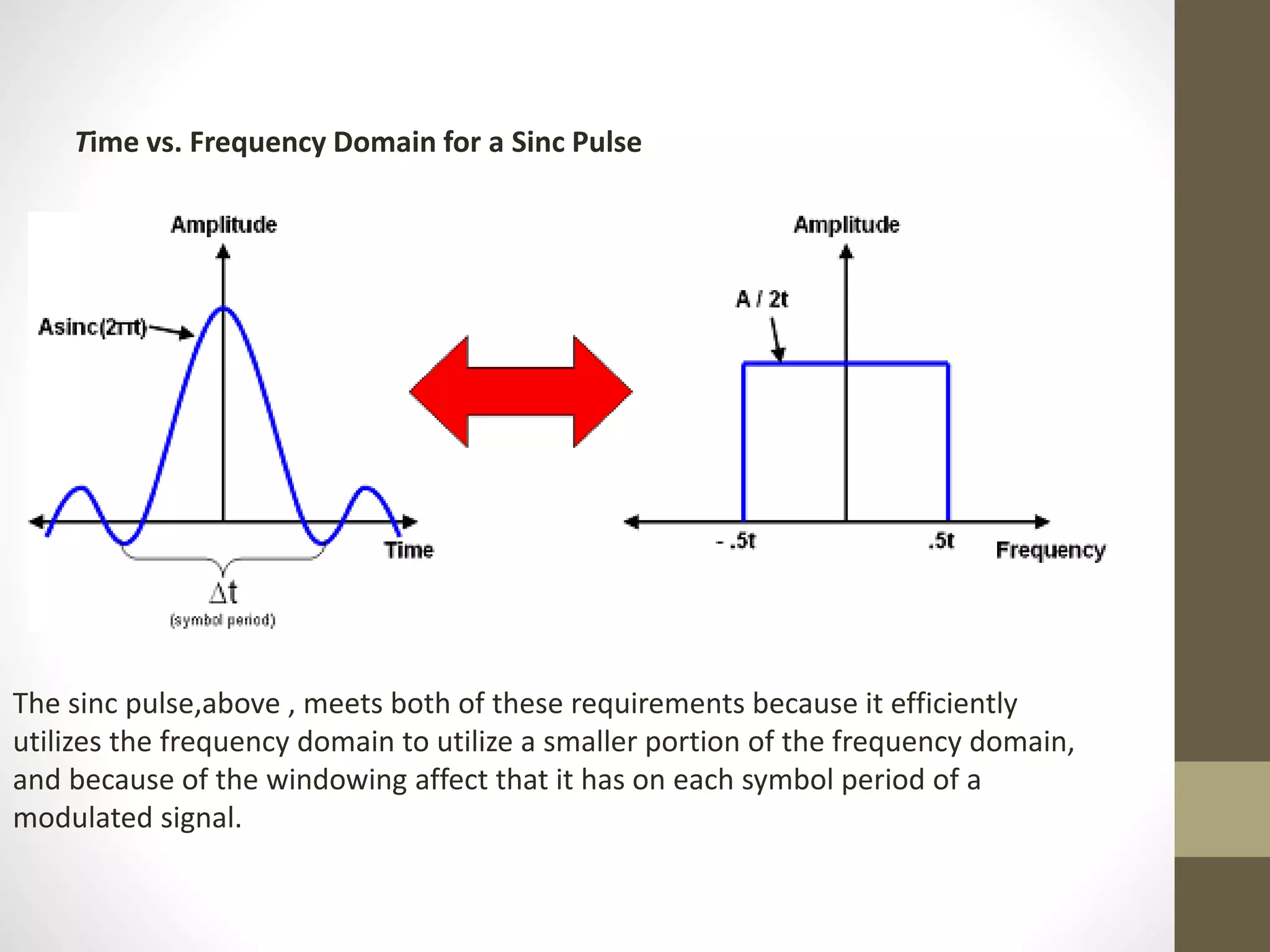
Sinc pulse utilization addressing frequency limitations and intersymbol interference in modulated signals.
Closing the presentation with an invitation for questions and expressing gratitude.