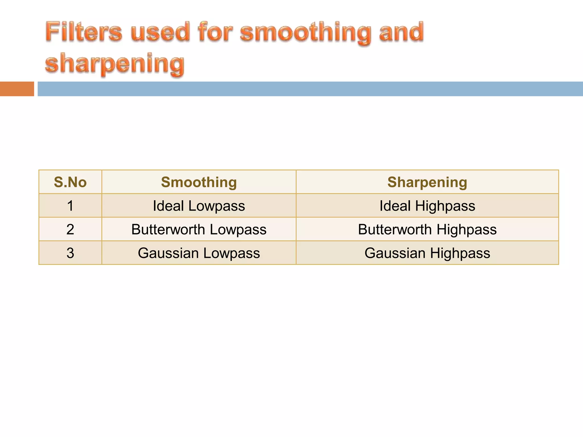
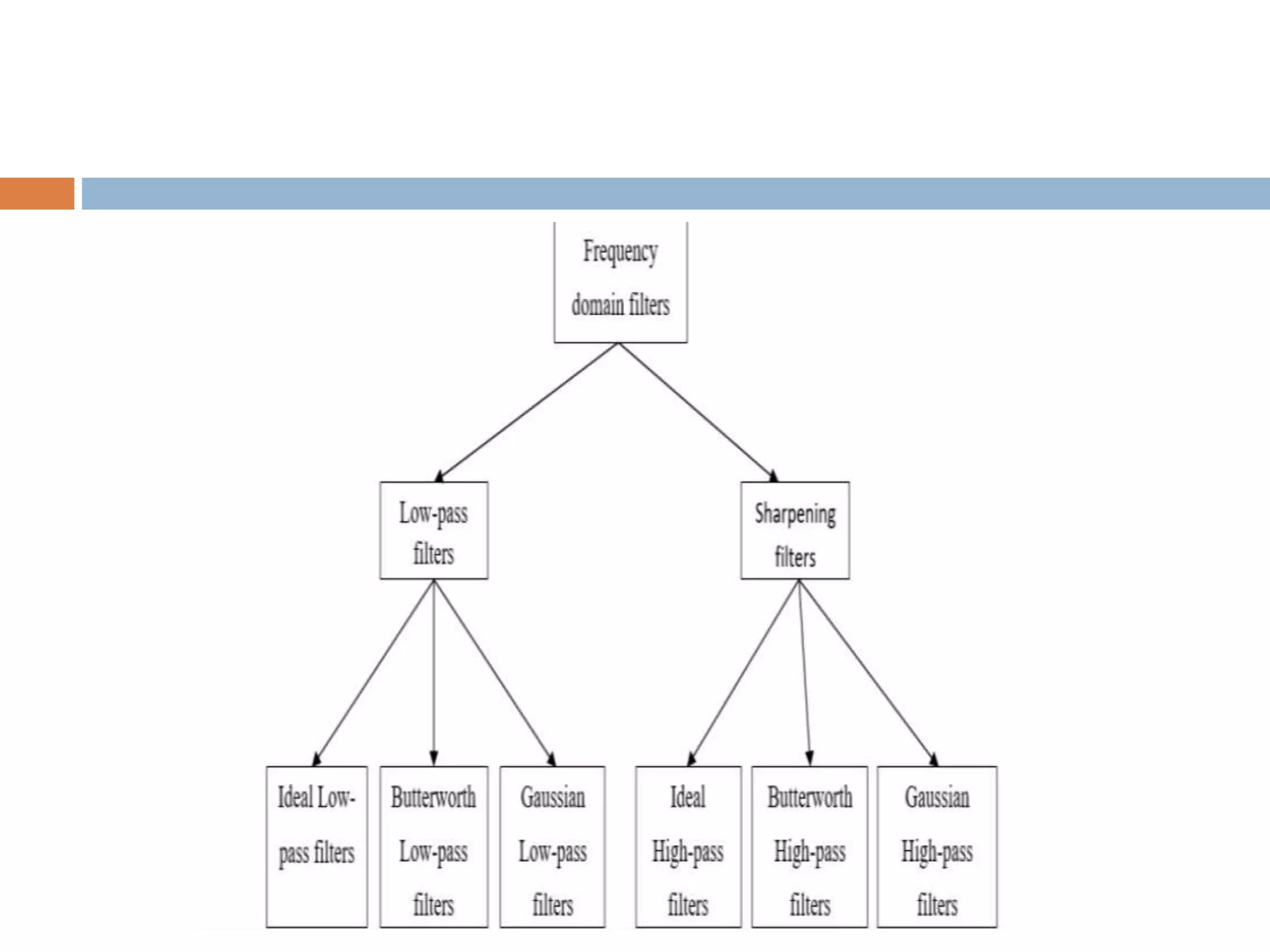
This document discusses various techniques for image enhancement in the frequency domain. It describes three types of low-pass filters for smoothing images: ideal low-pass filters, Butterworth low-pass filters, and Gaussian low-pass filters. It also discusses three corresponding types of high-pass filters for sharpening images: ideal high-pass filters, Butterworth high-pass filters, and Gaussian high-pass filters. The key steps in frequency domain filtering are also summarized.
Image Enhancement Spatial Domain & Frequency Domain Basic Steps in frequency domain Smoothing Sharpening
3.
Image enhancement isthe process of making images more useful The reasons for doing this include: – Highlighting interesting detail in images – Removing noise from images – Making images more visually appealing
5.
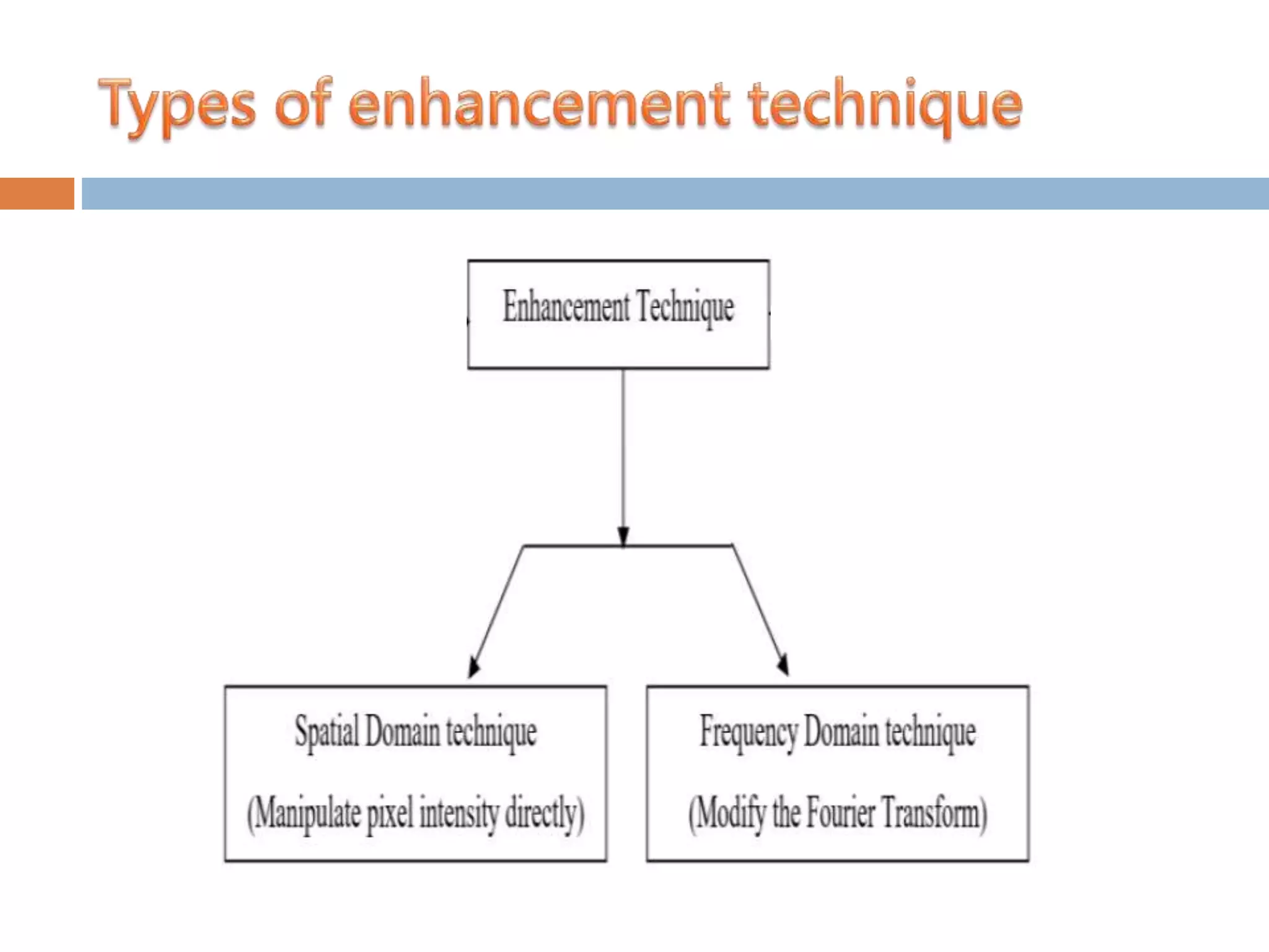
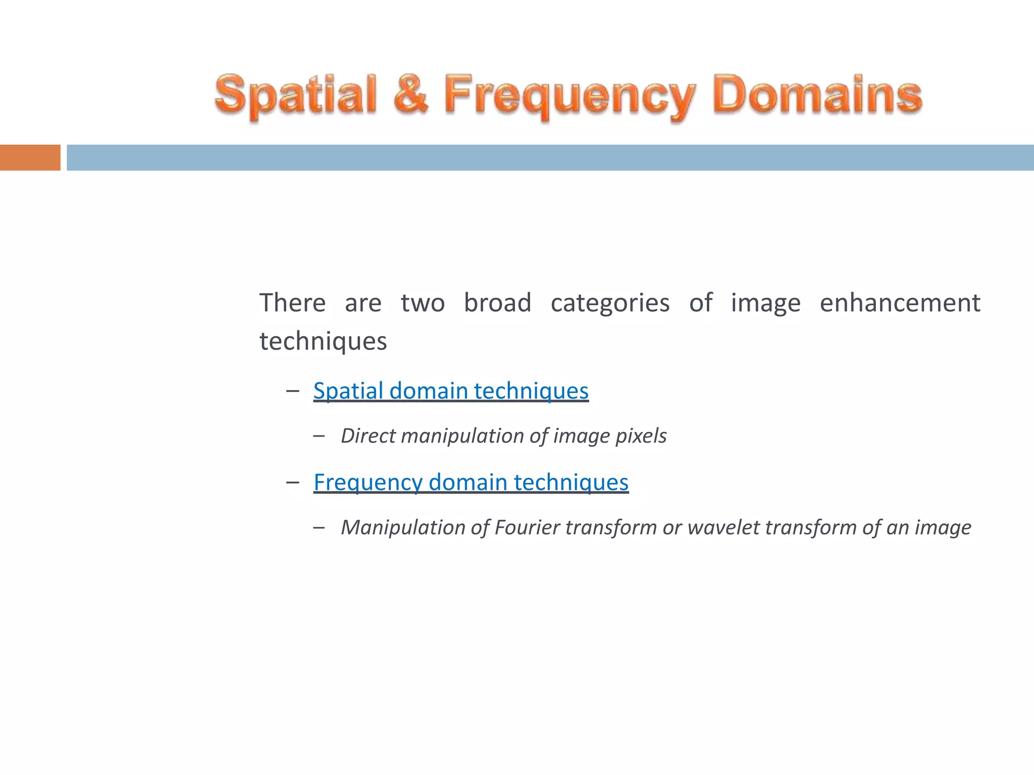
There are twobroad categories of image enhancement techniques – Spatial domain techniques – Direct manipulation of image pixels – Frequency domain techniques – Manipulation of Fourier transform or wavelet transform of an image
7.
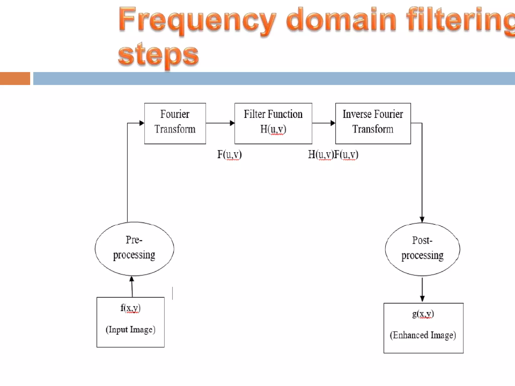
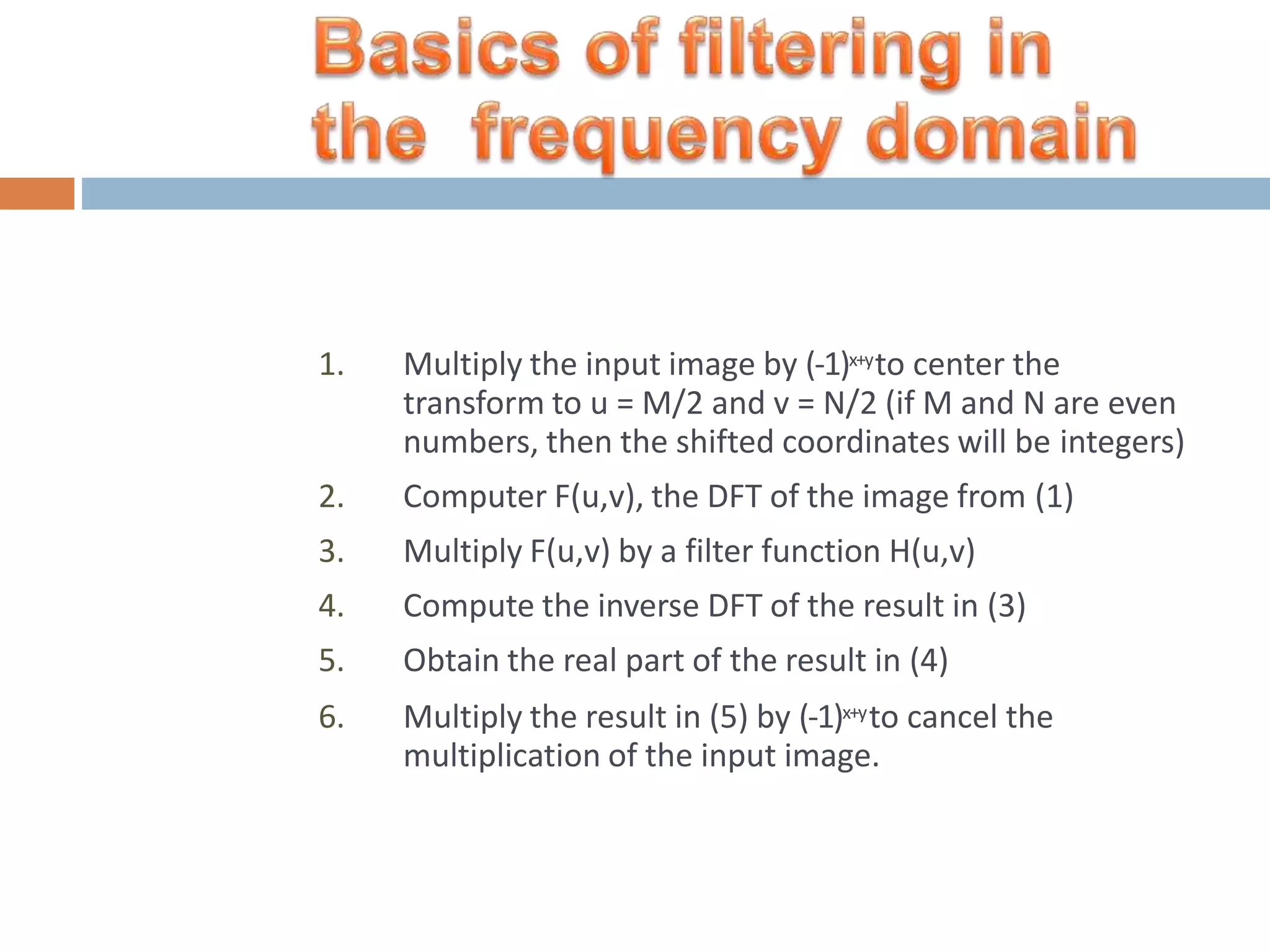
1. Multiply theinput image by (-1)x+yto center the transform to u = M/2 and v = N/2 (if M and N are even numbers, then the shifted coordinates will be integers) 2. Computer F(u,v), the DFT of the image from (1) 3. Multiply F(u,v) by a filter function H(u,v) 4. Compute the inverse DFT of the result in (3) 5. Obtain the real part of the result in (4) 6. Multiply the result in (5) by (-1)x+yto cancel the multiplication of the input image.
8.
The relationship betweenblurring mask and derivative mask with a high pass filter and low pass filter can be defined simply as. – Blurring masks are also called as low pass filter – Derivative masks are also called as high pass filter
9.
A blurring maskhas the following properties. – All the values in blurring masks are positive – The sum of all the values is equal to 1 – The edge content is reduced by using a blurring mask – As the size of the mask grow, more smoothing effect will take place
10.
A derivative maskhas the following properties. – A derivative mask have positive and as well as negative values – The sum of all the values in a derivative mask is equal to zero – The edge content is increased by a derivative mask – As the size of the mask grows , more edge content is increased
Smoothing(blurring) isachieved in the frequency domain by high- frequency attenuation; that is, by lowpass filtering. Here, we consider 3 types of lowpass filters: Ideal lowpassfilters Butterworth lowpassfilters Gaussian lowpassfilters These three categories cover the range from very sharp(ideal), to very smooth(Gaussian) filtering.
15.
The Butterworthfilter has a parameter called the filter order. For high order values, the Butterworth filter approaches the ideal filter. For low order values, Butterworth filter is more like a Gaussian filter. Thus, the Butterworth filter may be viewed as providing a transition between two “extremes”.
16.
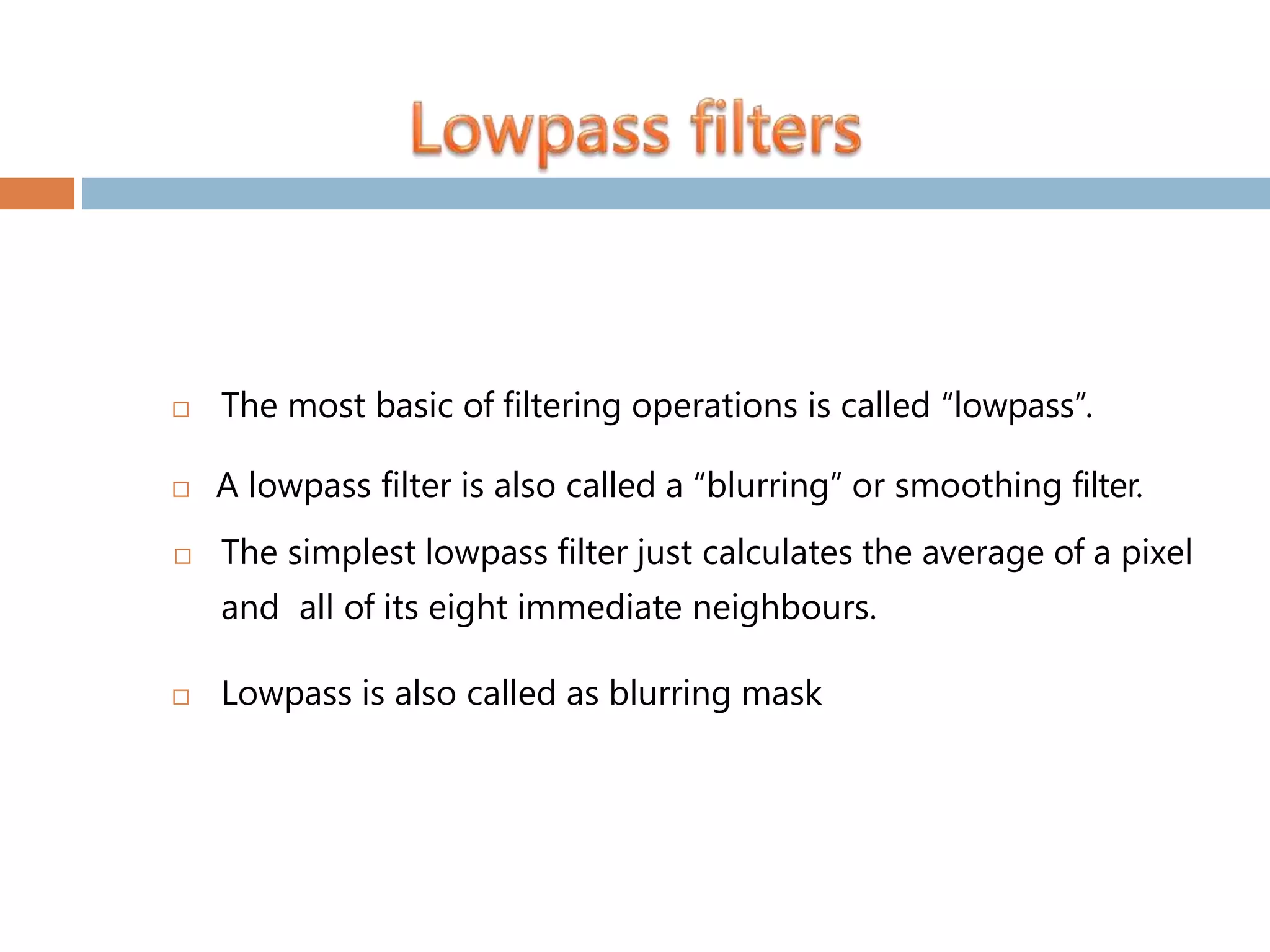
The mostbasic of filtering operations is called “lowpass”. A lowpass filter is also called a “blurring” or smoothing filter. The simplest lowpass filter just calculates the average of a pixel and all of its eight immediate neighbours. Lowpass is also called as blurring mask
17.
A 2-Dlow pass filter that passes without attenuation all frequencies within a circle of radius D0 from the origin and “cuts off” all frequencies outside this circle is called an ideal lowpass filter(ILPF); it is specified by the function. D0 is a positive constant and D(u,v) is the distance between a point (u,v) in the frequency domain and the center of the frequency rectangle; that is, D(u, v) [(u P / 2)2 (v Q / 2)2 ]1/ 2
18.
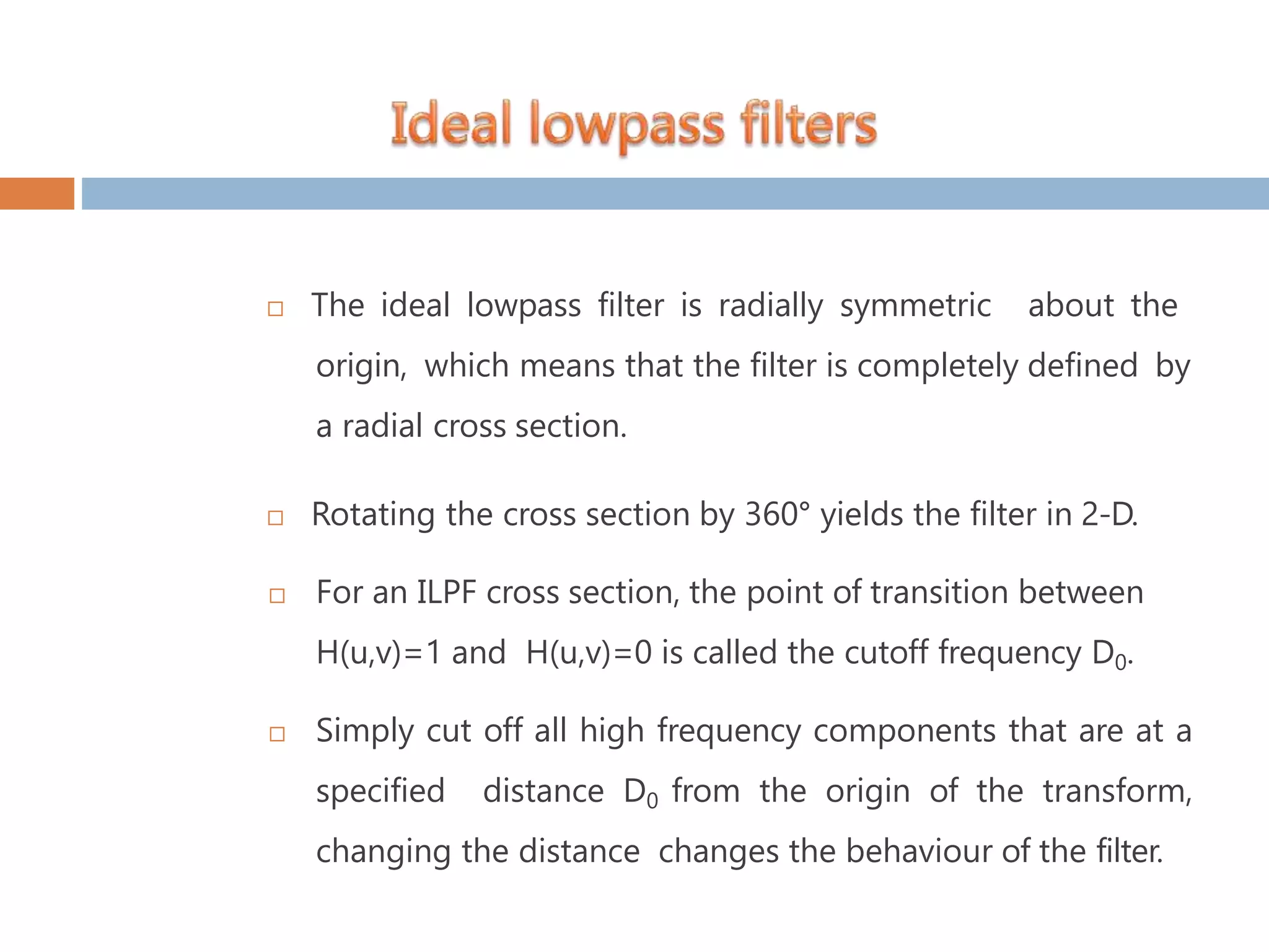
The ideallowpass filter is radially symmetric about the origin, which means that the filter is completely defined by a radial cross section. Rotating the cross section by 360° yields the filter in 2-D. For an ILPF cross section, the point of transition between H(u,v)=1 and H(u,v)=0 is called the cutoff frequency D0. Simply cut off all high frequency components that are at a specified distance D0 from the origin of the transform, changing the distance changes the behaviour of the filter.
19.
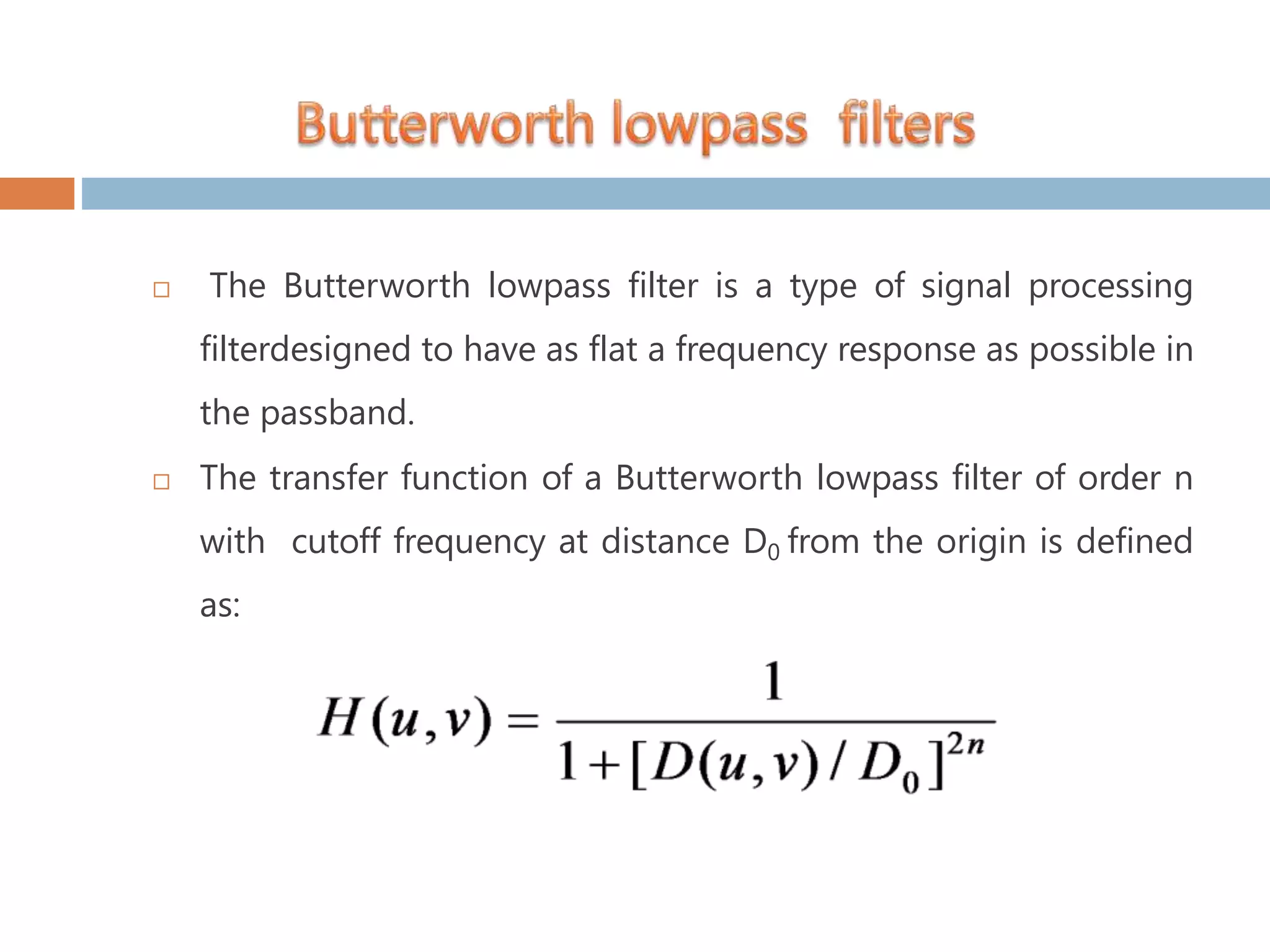
The Butterworthlowpass filter is a type of signal processing filterdesigned to have as flat a frequency response as possible in the passband. The transfer function of a Butterworth lowpass filter of order n with cutoff frequency at distance D0 from the origin is defined as:
20.
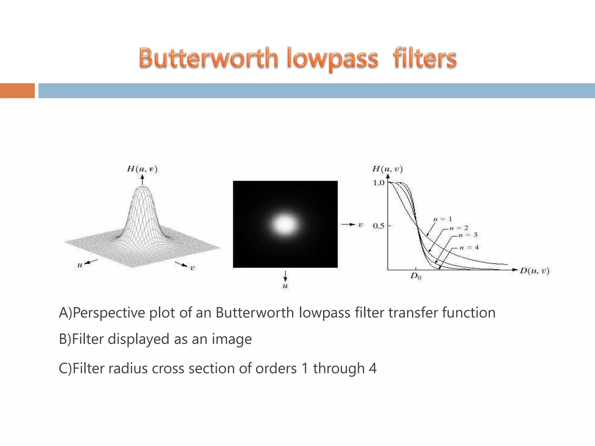
A)Perspective plot ofan Butterworth lowpass filter transfer function B)Filter displayed as an image C)Filter radius cross section of orders 1 through 4
21.
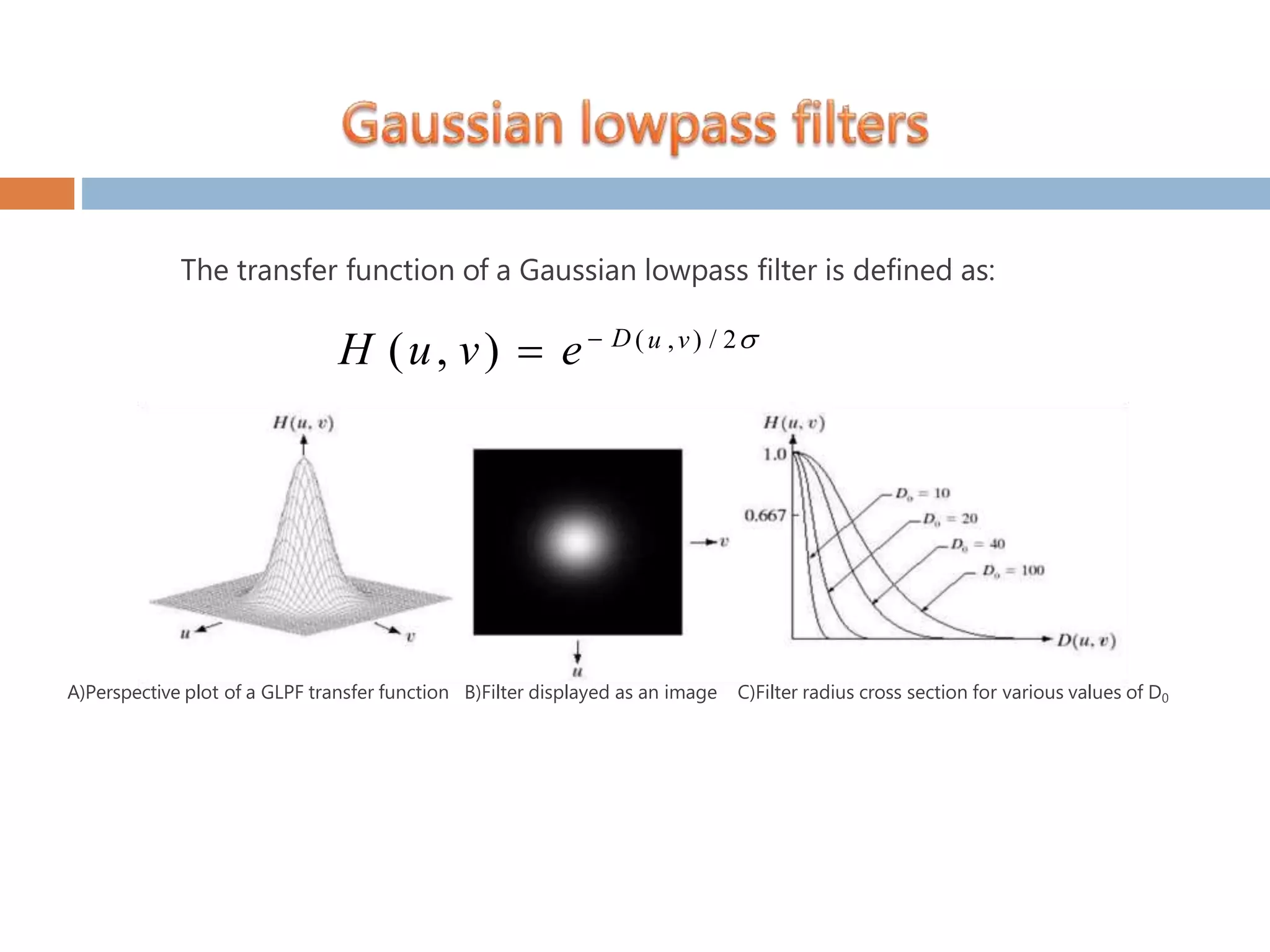
The transfer functionof a Gaussian lowpass filter is defined as: (u ,v) / 2 H (u, v) e D A)Perspective plot of a GLPF transfer function B)Filter displayed as an image C)Filter radius cross section for various values of D0
22.
Main advantageof a Gaussian LPF over a Butterworth LPF is that we are assured that there will be no ringing effects no matter what filter order we choose to work with.
23.
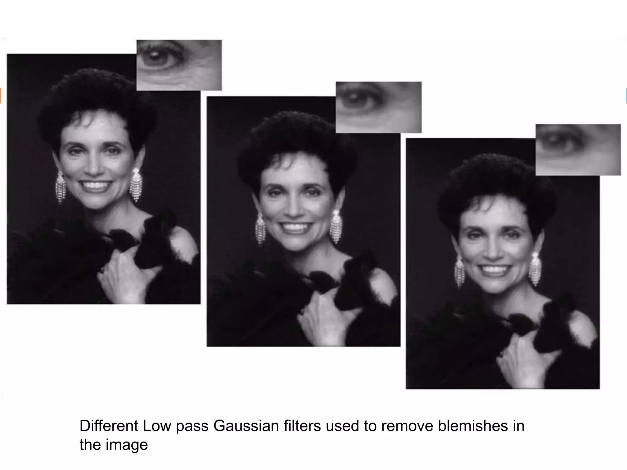
Different Low passGaussian filters used to remove blemishes in the image
24.
Edges and finedetail characterized by sharp transitions in image intensity Such transitions contribute significantly to high frequency components of Fourier transform Intuitively, attenuating certain low frequency components and preserving high frequency components result in sharpening
25.
– Intended goalis to do the reverse operation of low-pass filters – When low-pass filer attenuates frequencies, high-pass filter passes them Hhp (u,v) 1 Hlp (u,v) – When high-pass filter attenuates frequencies, low-pass filter passes them
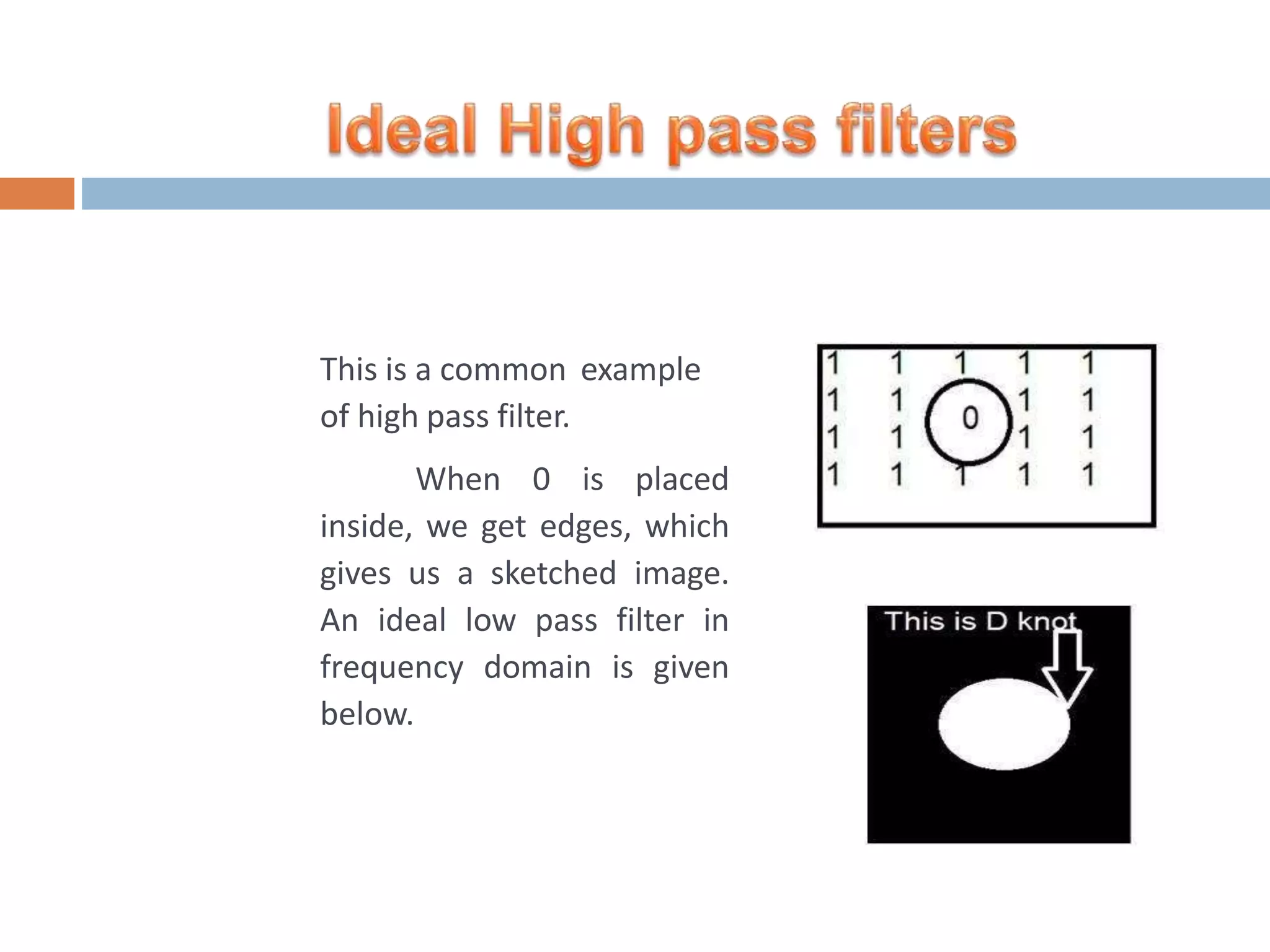
This is acommon example of high pass filter. When 0 is placed inside, we get edges, which gives us a sketched image. An ideal low pass filter in frequency domain is given below.
28.
The Butterworth highpass filter is given as: where n is the order and D0is the cut off distance as before 0 1 1[D / D(u,v)]2n H (u, v)
29.
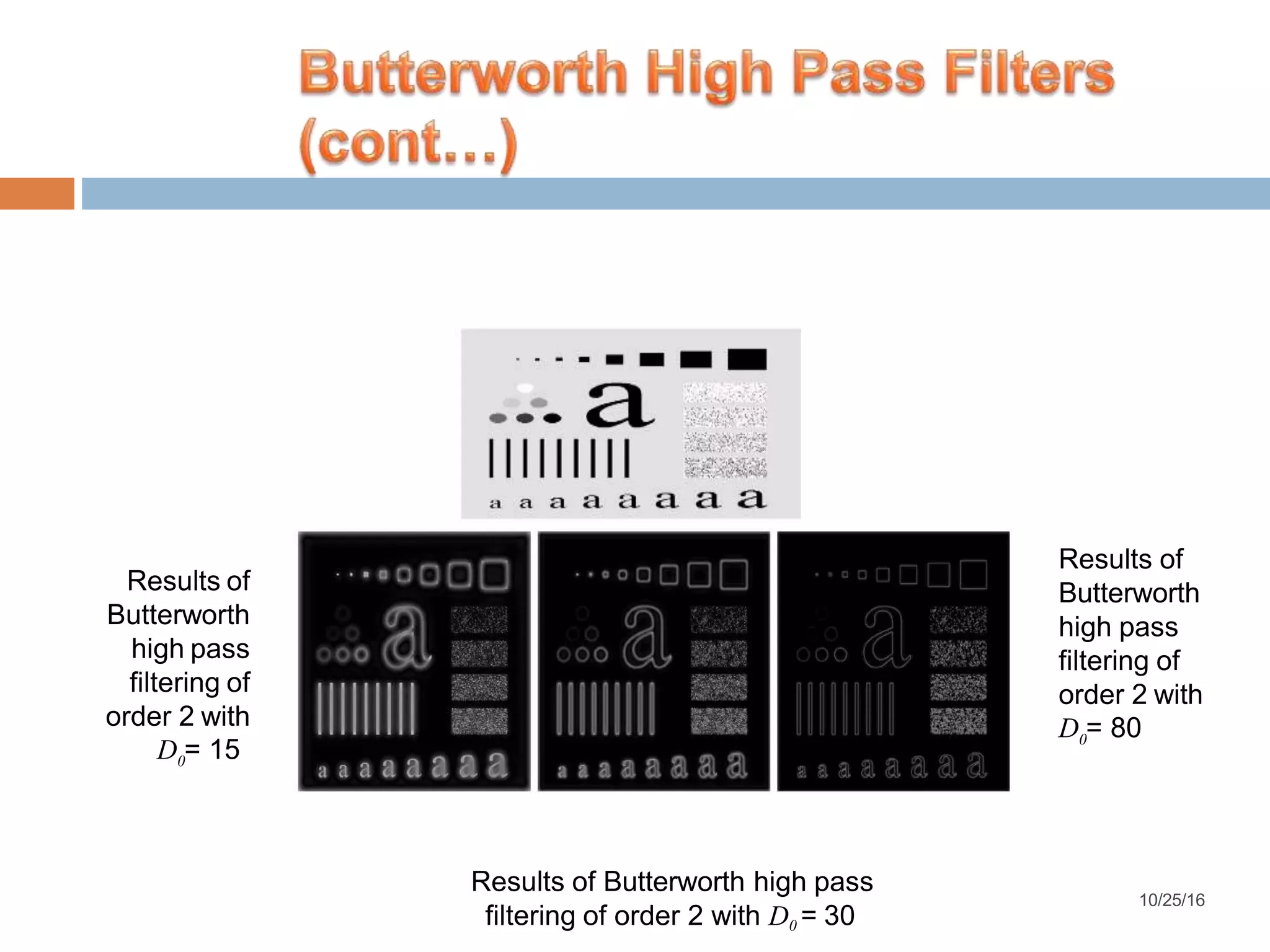
Results of Butterworth high pass filteringof order 2 with 0D = 15 Results of Butterworth high pass filtering of order 2 with filtering of order 2 with D0 = 30 0D = 80 Results of Butterworth high pass 10/25/16
30.
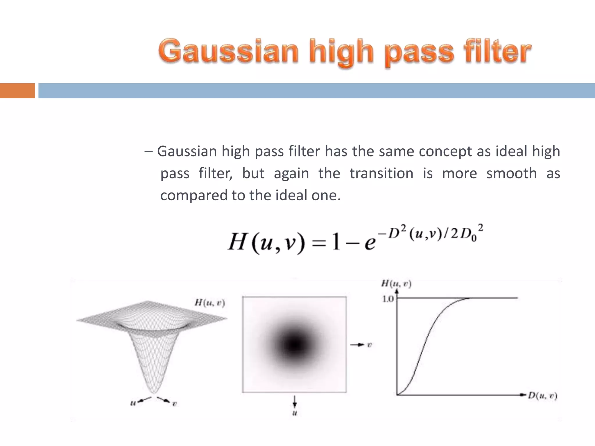
– Gaussian highpass filter has the same concept as ideal high pass filter, but again the transition is more smooth as compared to the ideal one.
31.
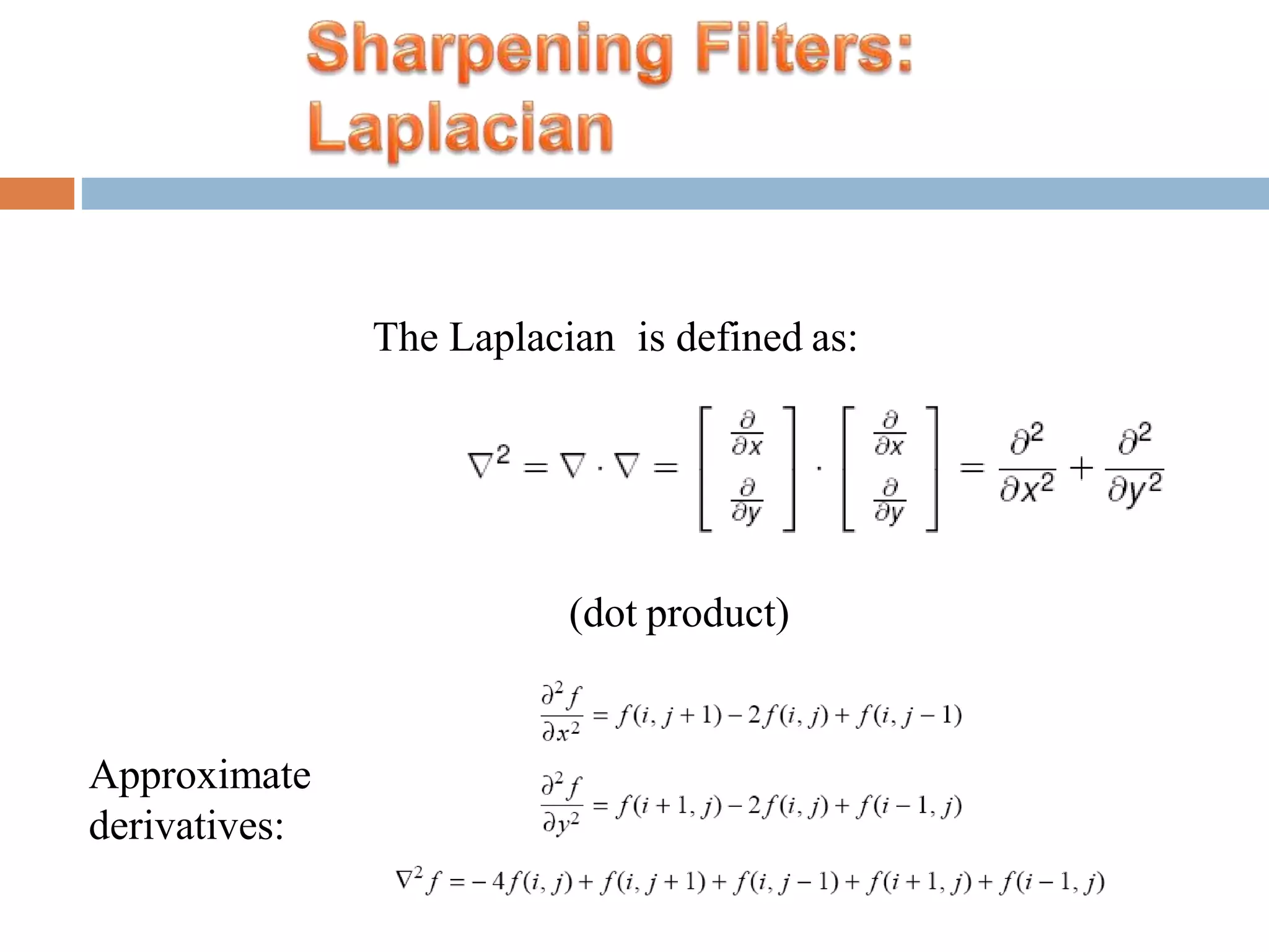
The Laplacian isdefined as: (dot product) Approximate derivatives:
The aimof image enhancement is to improve the information in images for human viewers, or to provide `better' input forother automated image processing techniques. There is no general theory for determining what is `good' image enhancement when it comes to human perception. If it looks good, it is good!
![ A 2-D low pass filter that passes without attenuation all frequencies within a circle of radius D0 from the origin and “cuts off” all frequencies outside this circle is called an ideal lowpass filter(ILPF); it is specified by the function. D0 is a positive constant and D(u,v) is the distance between a point (u,v) in the frequency domain and the center of the frequency rectangle; that is, D(u, v) [(u P / 2)2 (v Q / 2)2 ]1/ 2](https://image.slidesharecdn.com/finalkmsppt-1-180108082042/75/Image-Enhancement-using-Frequency-Domain-Filters-17-2048.jpg)
![The Butterworth high pass filter is given as: where n is the order and D0is the cut off distance as before 0 1 1[D / D(u,v)]2n H (u, v) ](https://image.slidesharecdn.com/finalkmsppt-1-180108082042/75/Image-Enhancement-using-Frequency-Domain-Filters-28-2048.jpg)