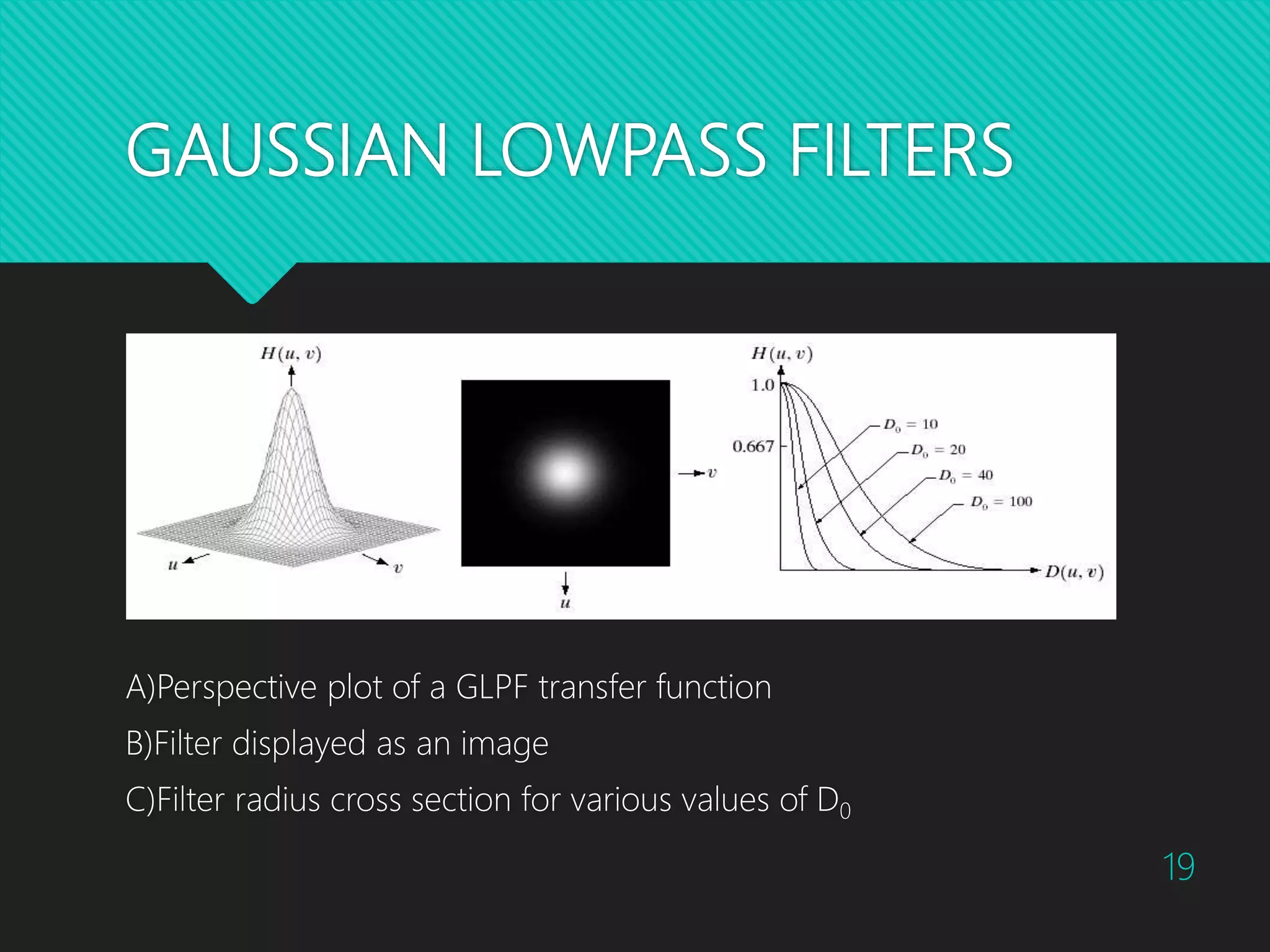
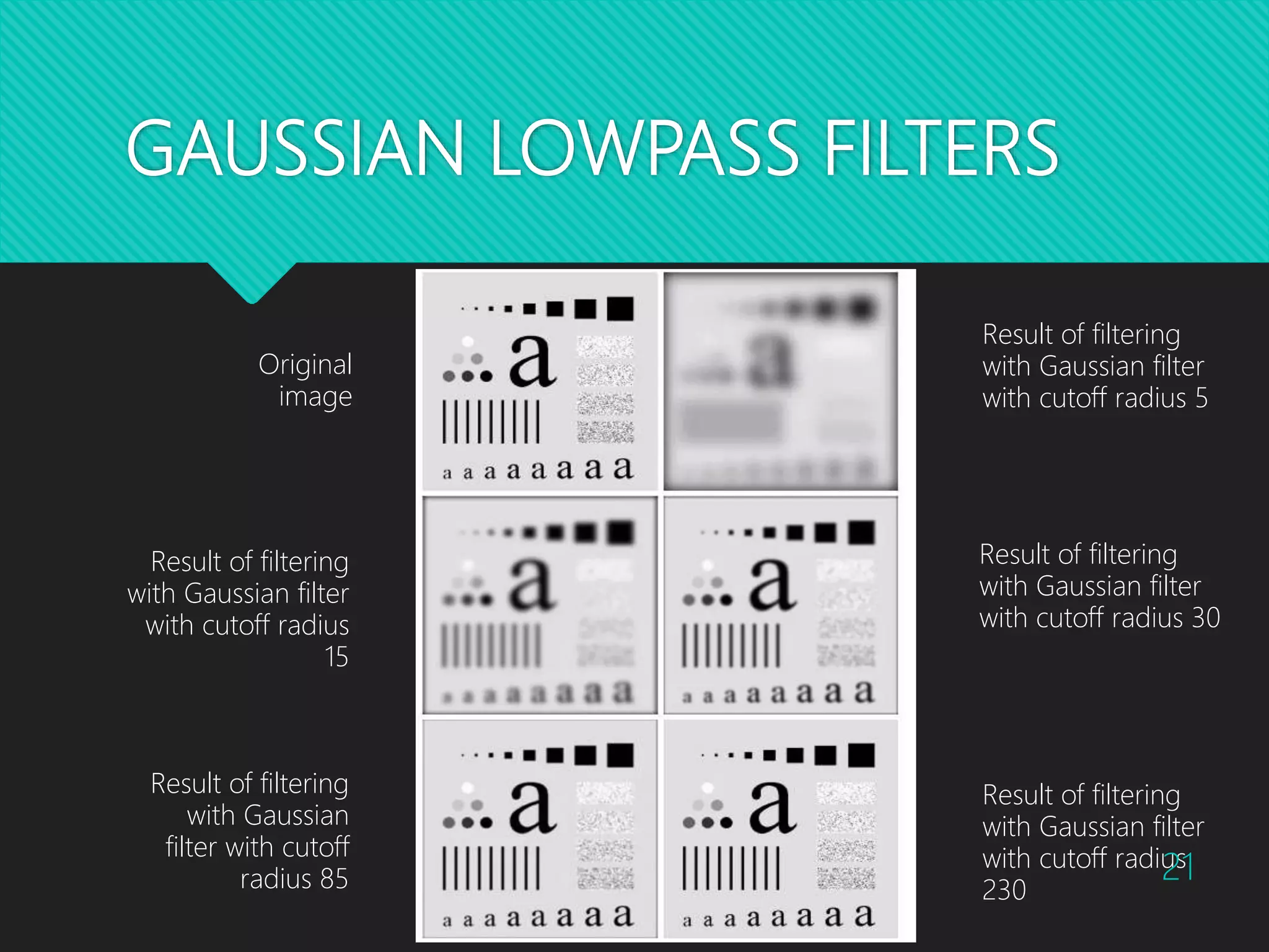
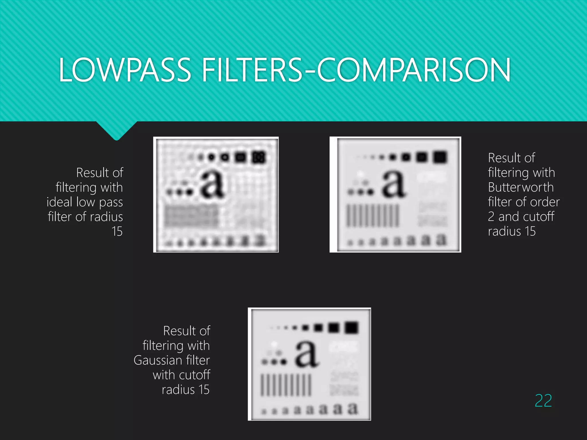
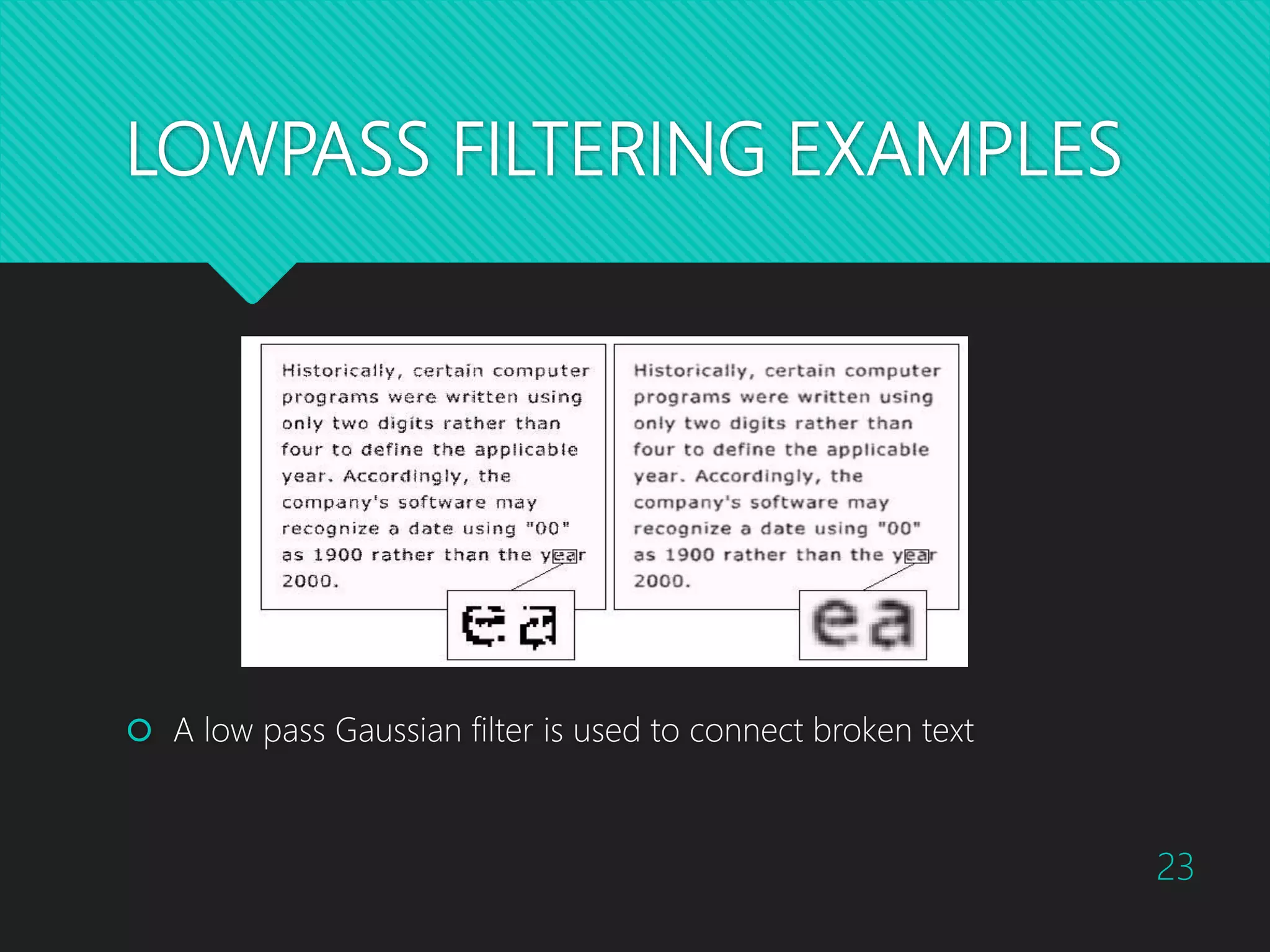
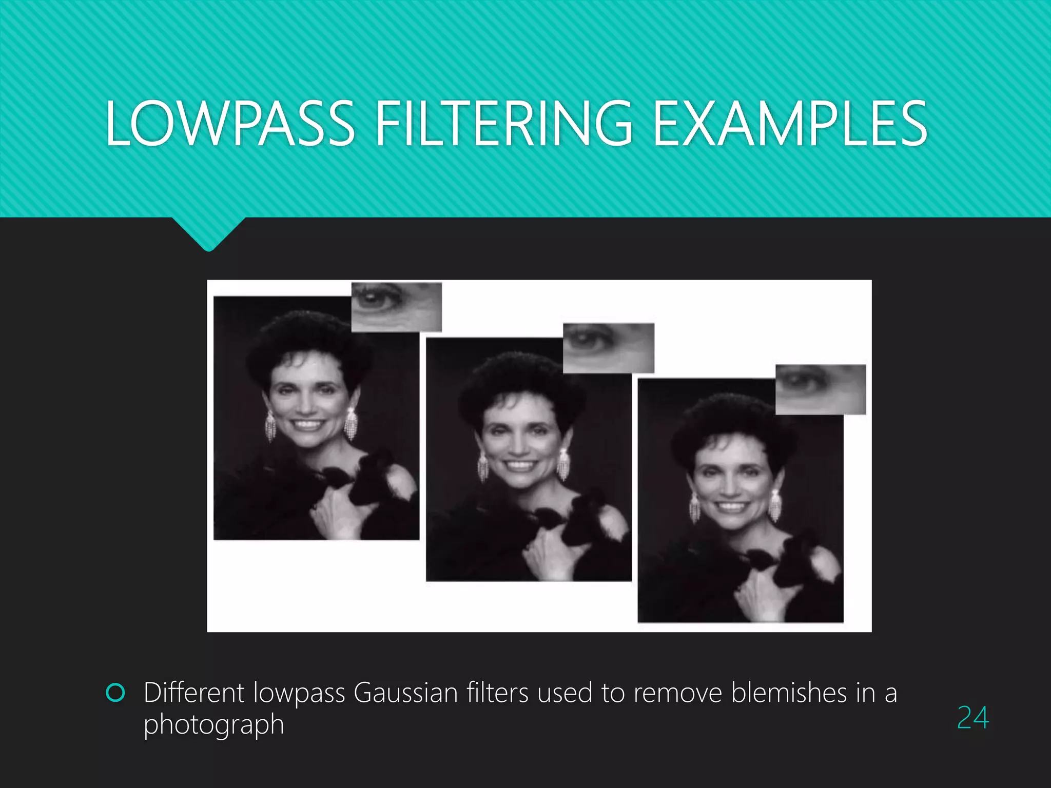
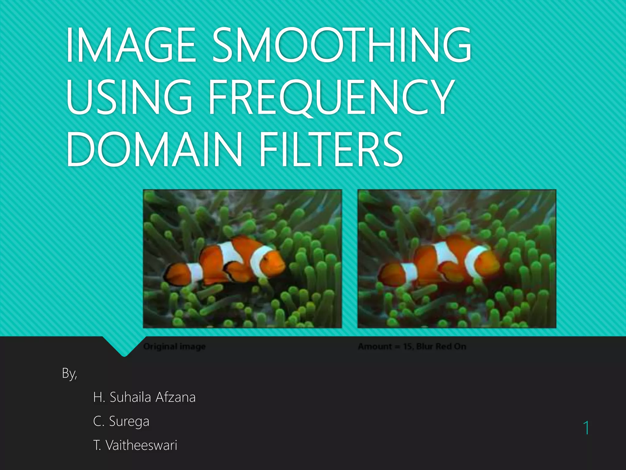
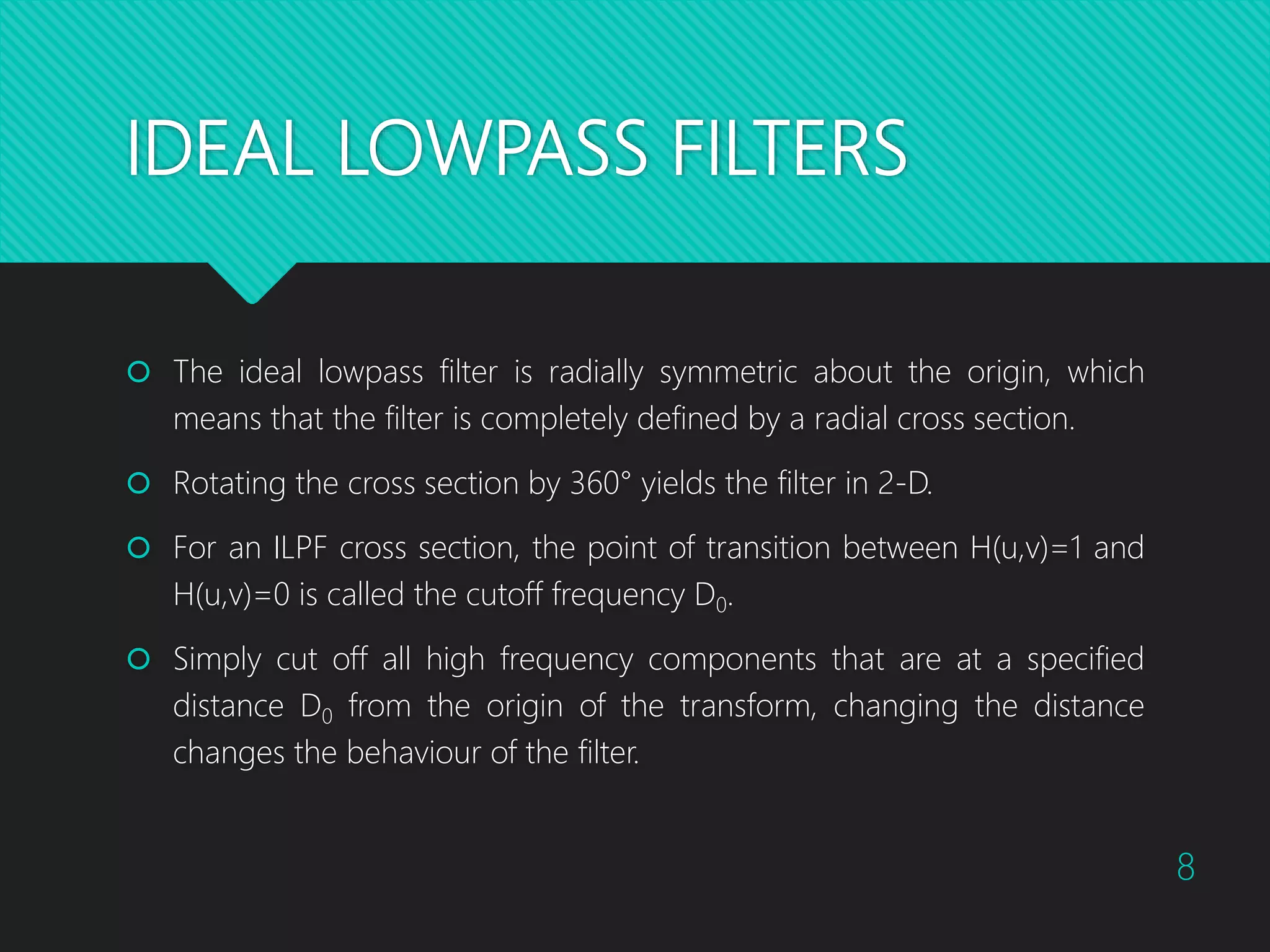
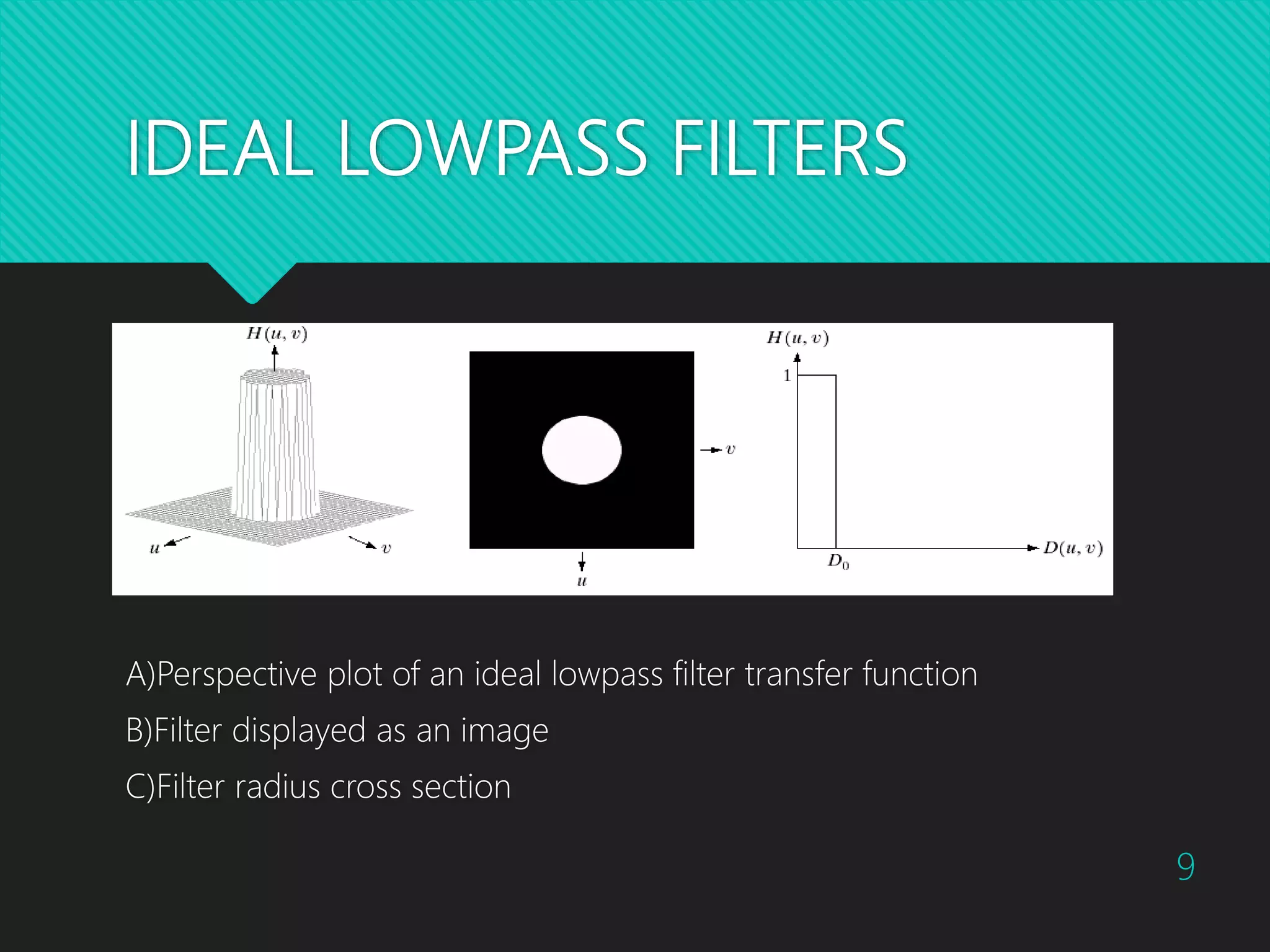
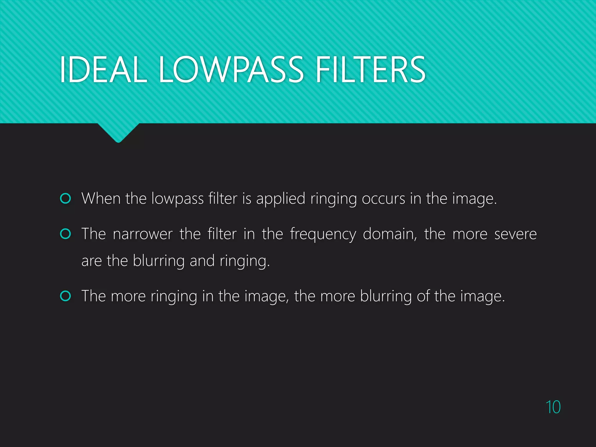
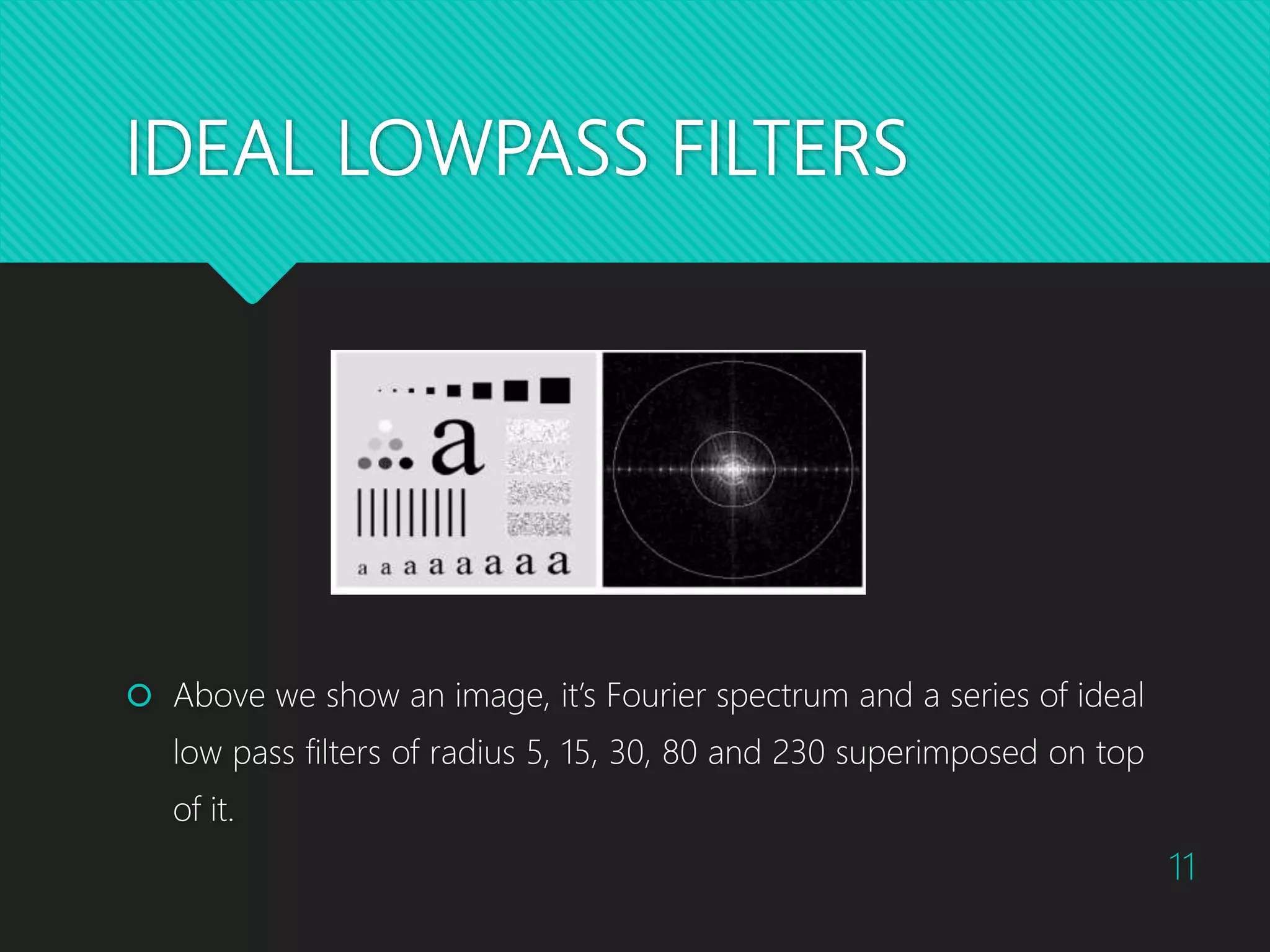
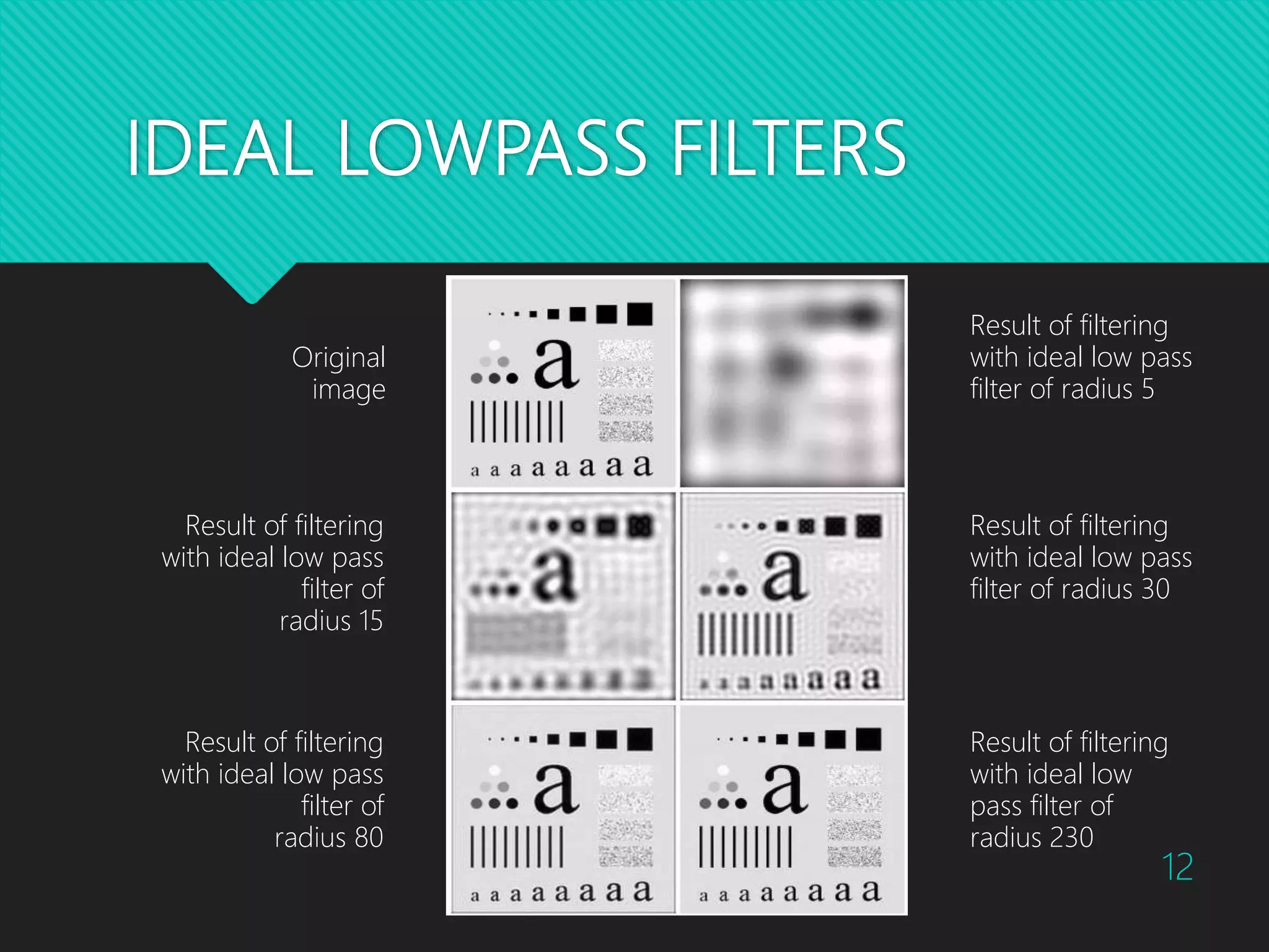
The document discusses image smoothing techniques using frequency domain filters, focusing on lowpass filters including ideal, Butterworth, and Gaussian filters. It explains how each filter operates, their characteristics, and how they compare in terms of sharpness and smoothness when used for blurring in images. Visual examples illustrate the effects of varying filter parameters on image quality.
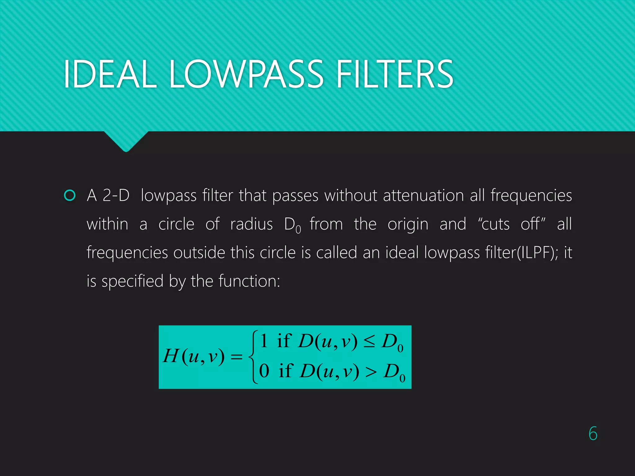
![IDEAL LOWPASS FILTERS D0 is a positive constant and D(u,v) is the distance between a point (u,v) in the frequency domain and the center of the frequency rectangle; that is, 2/122 ])2/()2/[(),( QvPuvuD 7](https://image.slidesharecdn.com/imagesmoothingusingfrequencydomainfilters-161024164202/75/Image-Smoothing-using-Frequency-Domain-Filters-7-2048.jpg)
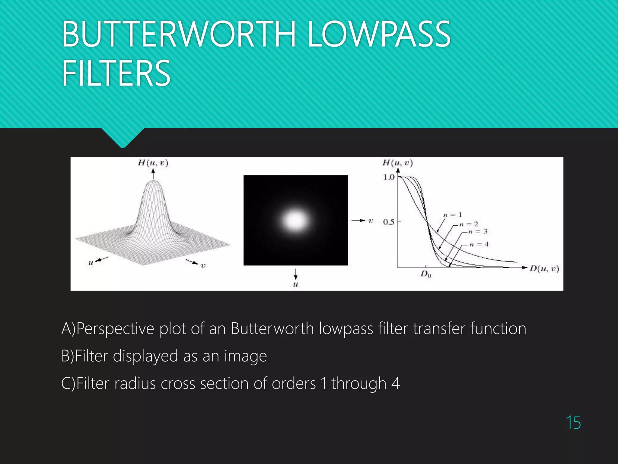
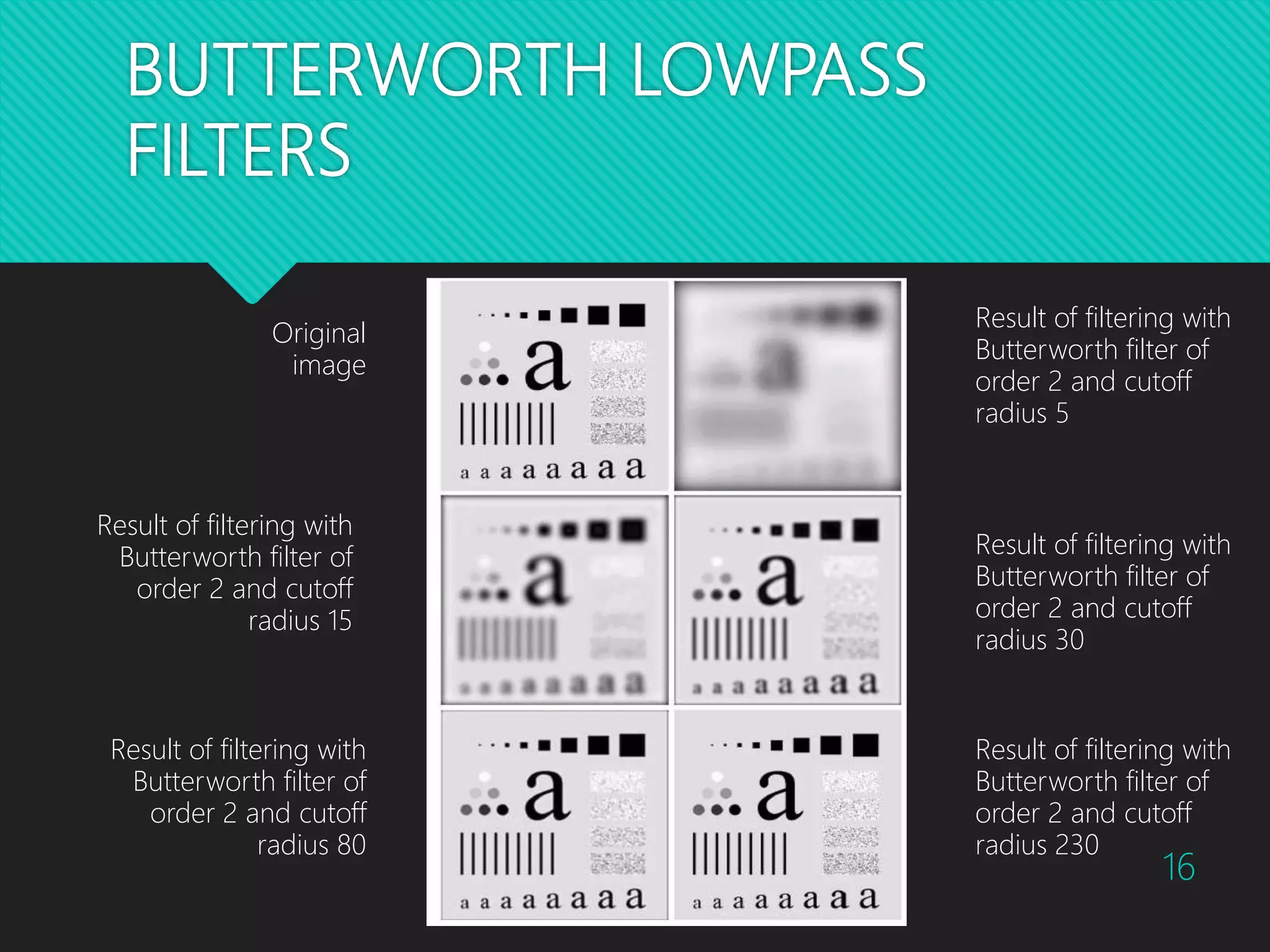
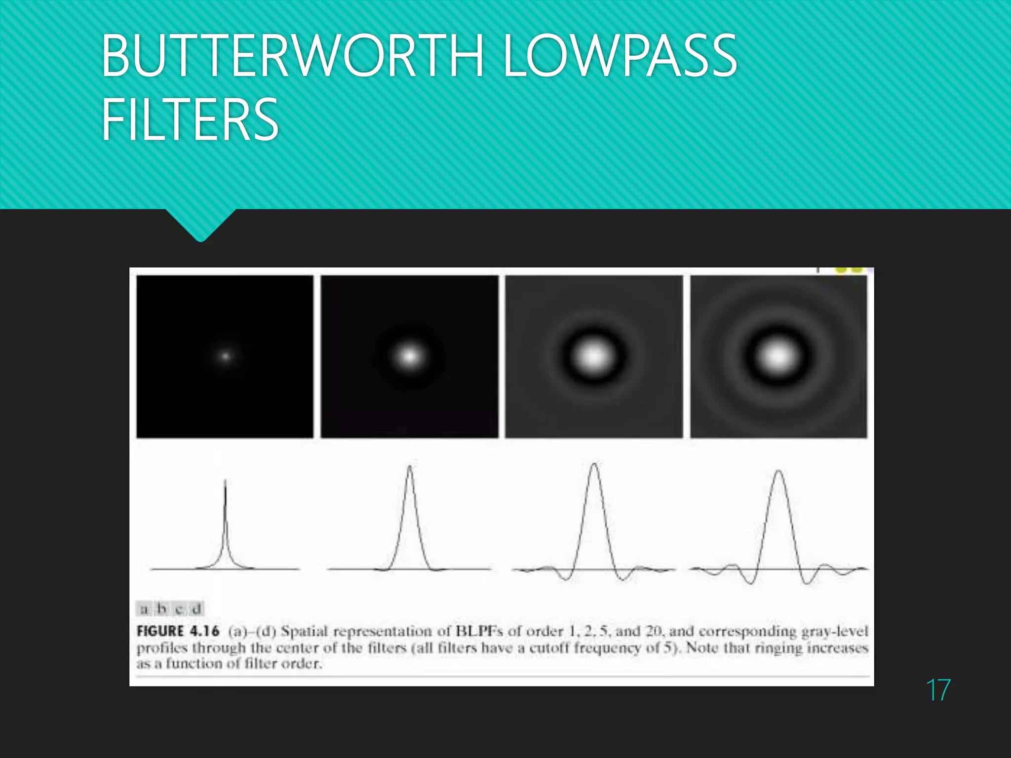
![BUTTERWORTH LOWPASS FILTERS The transfer function of a Butterworth lowpass filter of order n with cutoff frequency at distance D0 from the origin is defined as: n DvuD vuH 2 0 ]/),([1 1 ),( 14](https://image.slidesharecdn.com/imagesmoothingusingfrequencydomainfilters-161024164202/75/Image-Smoothing-using-Frequency-Domain-Filters-14-2048.jpg)