Download to read offline
![International Research Journal of Engineering and Technology (IRJET) e-ISSN: 2395-0056 Volume: 04 Issue: 06 | June -2017 www.irjet.net p-ISSN: 2395-0072 © 2017, IRJET | Impact Factor value: 5.181 | ISO 9001:2008 Certified Journal | Page 3165 Fuzzy Logic Based Path Navigation for Robot using Matlab Mrs. A. G. Andurkar1 , Ms. Rupali Tankar2, 1Professor, Dept. of Electronics & Telecommunication Engineering, Government College of Engineering, Jalgaon, maharashtra, india 2M.Tech Student, Dept. of Electronics & Telecommunication Engineering, Government College of Engineering, Jalgaon, maharashtra, india ---------------------------------------------------------------------***--------------------------------------------------------------------- Abstract: Robot navigation method is to drive a robot in the unknown environment to a designate position, the target, without collision. In this, we propose a robot navigation approach for dynamic environment with static and moving obstacles. The navigation method consists of staticnavigation method and dynamic path planning. The static navigation drives the robot to avoid the static obstacles by using fuzzy logic controller, which contains four input and two output variables. If the robot detects moving obstacles, the robot can recognize the velocity and moving direction of each obstacle and generatethecorrespondingTrajectoryPredictionTableto predict the obstacles future trajectory. If the tablerevealsthat the robot will collide with an obstacle, the dynamic path planning will find a new path to avoid the obstacle by waiting strategy or detouring strategy. Key Words: Fuzzy logic controller, Matlab, Path Navigation. 1. INTRODUCTION A robot is a programmable machine, able to extract information from its surrounding using different kinds of sensors or web camera to plan and execute collision free path by avoiding the obstacle in front of robot within its environment without human intervention. Navigation is a crucial issue for robots. A navigation system can be divided into two layers: High level global planning and Low-level reactive/local control. In high-level planning, a prior knowledge of environment is available and the robot workspace is completelyorpartiallyknown.Usingtheworld model, the global planner can determine the robot motion direction and generates shortest paths towardsthetarget in the presence of complex obstacles. However, since it is not capable of changing the motion direction in presence of unforeseen or moving obstacles, it fails to reach target or it may collide with the obstacle which came in their path. In contrast, in low-level local path planning, the robot work space is unknown and dynamic (presence of moving obstacle). It generates control commands based on coding given to the microcontroller, in whichthe robotusescurrent sensory information to take appropriate actions without planning process. Thus, it has a quick responseinreactingto unforeseen obstacles and uncertainties with changing the motion direction [3].6 Several Artificial intelligence techniques such as reinforcement learning, neural networks, fuzzy logic and genetic algorithms, can be applied for the reactive/local navigation of mobile robots to improve their performance. Amongst the techniques ability of fuzzy logic to represent linguistic terms and reliable decision making in spite of uncertainty and imprecise information makes it a useful method in control systems[4]. Fuzzy control systems are rule-based or knowledge-based systems containing a collectionoffuzzyIF-THEN rulesbased on the domain knowledge or human experts[6]. The simplicity of fuzzy rule-based systems,capabilitytoperform a wide variety tasks without explicit computations and measurements make it extensively popular among the scientists and researcher. 2. SYSTEM DESCRIPTION 2.1 Design of a Fuzzy Controller The schematic diagram of the fuzzy controller is shown in Fig-1. The fuzzy controller design steps include: 1) Initialization, 2) Fuzzification, 3) Inference and 4) Defuzzification. Fig-1: The fuzzy controller structure First step is identifying the linguistic input and output variables and definition of fuzzy sets (Initialization). Fuzzification or fuzzy classification is the process of converting a set of crisp data into a set of fuzzy variables using the membership functions (fuzzy sets). A rule base is obtained by a set of IF-THEN rules and inference evaluates the rules and combines the result of the rules. Objective of this part is to transform the subsets of theoutputswhichare calculated by the inference engine. The final step is Defuzzification which is the process of converting fuzzy rules into a crisp output[5]. OUTPUT INPUT](https://image.slidesharecdn.com/irjet-v4i6761-180309064434/75/IRJET-Fuzzy-Logic-Based-Path-Navigation-for-Robot-using-Matlab-1-2048.jpg)
![International Research Journal of Engineering and Technology (IRJET) e-ISSN: 2395-0056 Volume: 04 Issue: 06 | June -2017 www.irjet.net p-ISSN: 2395-0072 © 2017, IRJET | Impact Factor value: 5.181 | ISO 9001:2008 Certified Journal | Page 3166 3. HARDWARE DESCRIPTION 3.1 Block Diagram of Path Navigation System Fig-2: Block diagram of path navigation system Path navigation system requires following hardware as shown in Fig-2 which gives an overview of interconnection among various components. Atmega 16A PU L293D Motor driver IC DC motor Infrared sensor The experimental prototype, showninFig-2,isa rectangular shaped differentially steered robot. One infrared sensor is provided which is input to the microcontroller. A microcontroller board incorporating Atmega16A PU microcontrollers is designed to run fuzzy controllers. The infrared sensors present at the front of the robot constantly monitor the nearby environmentforobstacles,theobstacles are assumed to be real-life obstacles,i.enotbelongingto any particular shape or known structure. The sensors, after suitable calibration, provide analog voltage output proportional to the distance between a sensor and an obstacle. This analog voltage value is fed to the ADC of the Atmega16, which samples itandconvertsitintodigital form, to be used for further processing. The fuzzy rule base, has been burnt in the microcontroller, after coding. The VERY CLOSE, CLOSE and FAR distancesfor obstacles are considered as 3 digital threshold values in the digital domain for programming purposes. After, the processing is done by the microcontroller for the given code’s logic, the required output pins are activated (PORT B), which are connected to the motor driver circuit L293D. To drive the dc motors from microcontroller, a motor interface board is designed using L298D integrated circuit chips. The motor driver circuit makes the wheels of the robot go forward or backward based upon the polarities of voltages at its 4 outputs. Two dc motors independently control two wheels on a common axis. Two caster wheels are provided for support. Then, the rear wheels are fitted in the grooves and the castor wheel is fitted at the front as an alternative to fitting two more front wheels. Then, the DC motors are fittedtothe rear axles[7]. These motors are specially designed motors that provide high torque to the wheels. Sensor modules are then fitted at the front, of the robot.Thendrillingandcutting operations are carried out to fix various components into the chassis. Sensors are checked for correct working by waving one’s hand in front of them. The detection of an obstacle by the sensor is confirmed by the glow of a LED. Then, the sensors are calibrated by setting the range of detection of all sensors equal. This canbedone bytuningthe potentiometer knob present onthesensor.Thisisimportant to ensure that all sensors detect the presence of an obstacle from the same distance,whichisofutmostimportancewhile taking turns and especially sharp turns. The motor driver module should also be checked by giving power supply and checking the voltage at its output pins by a multi-meter. It should also be checked and ensured that the wheels are moving parallel. The sensors are suitably calibrated to provide analog voltages proportional to the distance between sensor and obstacle. ThealignmentoftheIRsensor LEDs should be made pointing outwards from theirlocation on the robot’s body and all the sensors should be checked properly for this[8]. This will ensure seamlessacquisition of input obstacle distances from the environment by both sensors present on each of the three sides of the robot. 3.2 Operation of The Robot General program for the robot operation is createdforrobot rules. At first step the program read all sensors value that attached to the robot. Then the distance value of obstacle sensor is calculated. Theprogramreceivesrangingdata from the sensors then uses this to conduct the fuzzy logic operations[6]. Robot then will maketheturnsleft,then right, then right and returns to original path to avoid the obstacle depend on the output of the fuzzy logic program. When the turning process is complete, the sensor detectsorreadagain for the next input. If there is obstacle again, the avoiding process still running until there is no obstacle[1]. If no obstacle is detected, the robotwill moveforwardinfast condition. After each movement, then the sensor is read again to continue the next movement process. From the sensor reading, the mathematical rule is applied to find the obstacle distance and obstacle difference value. Infrare d Sensor Atmega 16A PU 1404 L293D Motor Driver IC DC Motor](https://image.slidesharecdn.com/irjet-v4i6761-180309064434/75/IRJET-Fuzzy-Logic-Based-Path-Navigation-for-Robot-using-Matlab-2-2048.jpg)
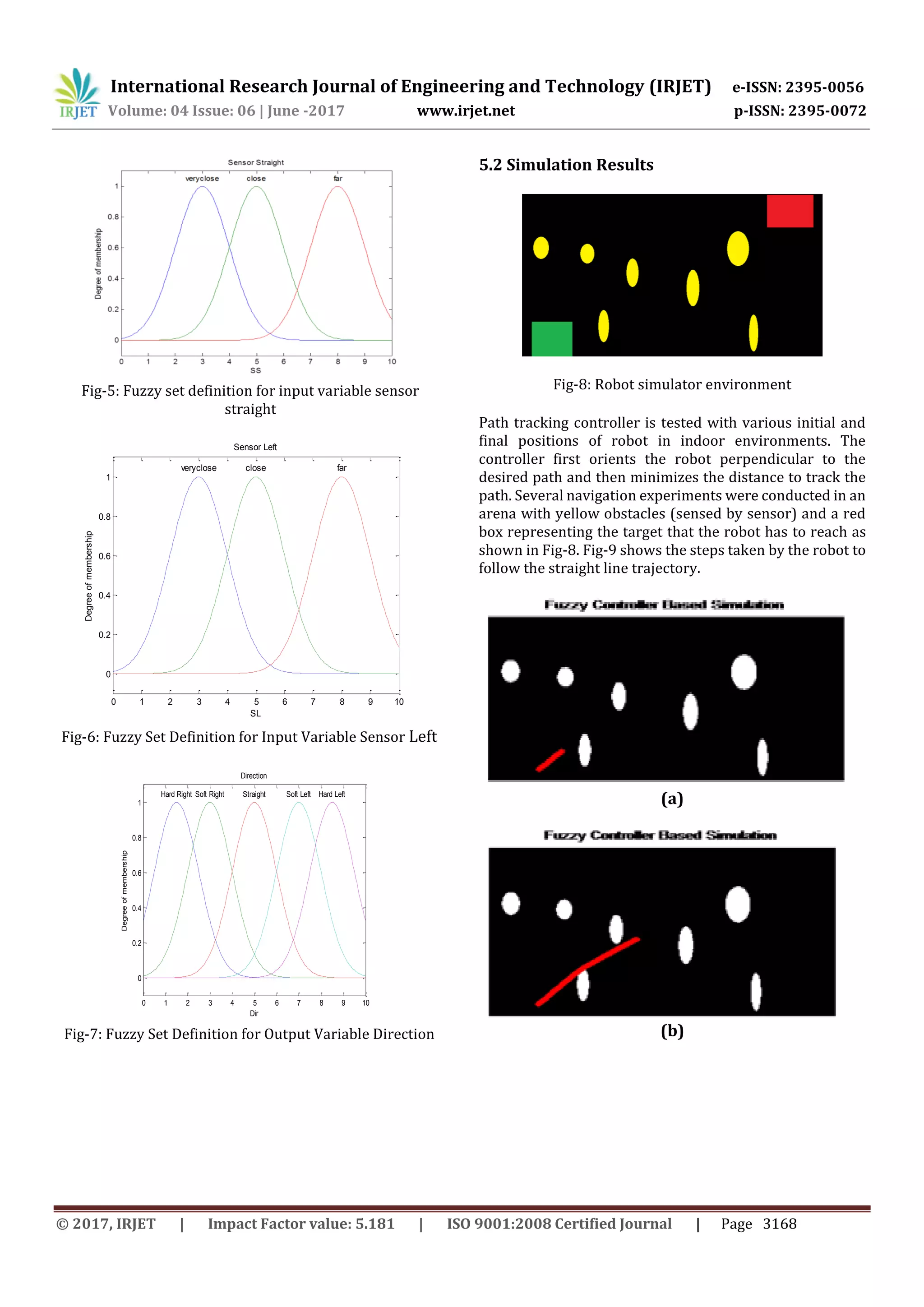
![International Research Journal of Engineering and Technology (IRJET) e-ISSN: 2395-0056 Volume: 04 Issue: 06 | June -2017 www.irjet.net p-ISSN: 2395-0072 © 2017, IRJET | Impact Factor value: 5.181 | ISO 9001:2008 Certified Journal | Page 3167 3.3 Circuit Diagram Fig-3: Circuit diagram of path navigation system Fig-3 shows a circuit diagram for fuzzy logic based path navigation for robot. In this path navigation robot, we have used an infrared sensor for detecting obstacle in front of the robot and a comparator IC for comparing voltages. Comparator configured in non-inverting mode and 10K potentiometer is connected at its inverting terminal for adjusting reference voltageandinfraredreceiver’sisdirectly connected to non-inverting pins of comparator.One redLED is connected at output of in the sensor board, when this led blinks then it means our sensor is working, then signal goes to microcontroller IC Atmega16A PU which is programmed and gives the output to the motor driver IC l293d having basic function to increase the voltage and current required to operate the dc motor. Then L293D motor IC rotates the motor as per the programming of microcontroller IC. Thus the motor driver IC is responsible for the wheels movement i.e forward, left, right[1][2]. 5. RESULT AND DISCUSSION 5.1 FUZZY SETS OF THE INPUT AND OUTPUT 0 1 2 3 4 5 6 7 8 9 10 0 0.2 0.4 0.6 0.8 1 SR Degreeofmembership veryclose close far Sensor Right Fig-4: Fuzzy Set Definition for Input Variable Sensor Right There are three inputs to the fuzzy logic system and one output. The inputs are basically the sensor right (Fig-4), the sensor straight (Fig-5), and sensor left (Fig-6). Output is direction ( Fig-7). This particular set of sets are equally spaced on the input range of 0 to 10. The vertical axis of this graph is degree of membership that goes from 0 to 1. According to input, robot changes its direction. If (SR is far) and (SS is far) and (SL is far) then (Direction is Straight) If (SR is far) and (SS is far) and (SL is close) then(Directionis Soft Right) If (SR is far) and (SS is far) and (SL is veryclose) then (Direction is Hard Right) If (SR is far) and (SS is close) and (SL is far) then(Directionis Soft Right) If (SR is far) and (SS is close) and (SL is close) then (Direction is Soft Right) If (SR is far) and (SS is close) and (SL is veryclose) then (Direction is Hard Right) If (SR is close) and (SS is far) and (SL is far) then(Directionis Soft Left) If (SR is close) and (SS is close) and (SL is far) then (Direction is Soft Left) If (SR is veryclose) and (SS is far) and (SL is far) then (Direction is Hard Left)](https://image.slidesharecdn.com/irjet-v4i6761-180309064434/75/IRJET-Fuzzy-Logic-Based-Path-Navigation-for-Robot-using-Matlab-3-2048.jpg)
![International Research Journal of Engineering and Technology (IRJET) e-ISSN: 2395-0056 Volume: 04 Issue: 06 | June -2017 www.irjet.net p-ISSN: 2395-0072 © 2017, IRJET | Impact Factor value: 5.181 | ISO 9001:2008 Certified Journal | Page 3169 (c) (d) Fig-9: Robot moving towards target In this section, the mobile robots have to navigate in environment with obstacles. Fig-9 shows the step by step behaviour of robot that the proposed algorithm avoids the obstacle[2]. We notice that if the infrared range sensors detect an obstacle, the robot is forced to make an adequate turn to avoid collision with the object. The navigation is a process of locating position from where the robot will search the moving path. If we are considering the movement of robot in the given environment.According to the environment given we have to set up the image representation. Let select the image where you need to move that robot. After selecting the environment in the let select the start point by double clicking on that specified point. Also select the end point by double clicking on thatspecifiedpoint.Now the program will find the shortest path and it will show the model image containing the path direction[1]. For the navigation process we need programming on fuzzy controller. Controlling the direction is basic task. It will initialize the fuzzy controller for operating the direction of robot[1]. After initializing the fuzzy controller navigation process will start. It will show the exact moving path of the robot. The visualization will also show the direction one by one. Say, if the robot is moving to the left direction it will show left. Also same for straight and right direction. After completion it will show the simulation process will end. 6.1 Conclusions Review of different works showed that Fuzzy Logic control is one of the most successful techniques in the design and coordination of behaviors for mobile robots navigation. In this chapter first we performed a study to describe how the fuzzy logic can be applied to design individual behaviors simply and solve complex tasks by the combination of the elementary behaviors[9]. The Fuzzy control addressed a useful mechanism to design various behaviors by the use of linguistic rules. It also provided a robust methodology for combination and arbitration of behaviors. Then, two fuzzy controllers designed to demonstrate influence and robustness of the fuzzy control in a navigation system. The obtained results proved the successful operation and effectiveness of the fuzzy control in generating smooth motion, reducing navigation time and increasing the robot safety[10]. Overall, advantages of fuzzycontrol inthedesign of a navigation system are: i) Capability of handling uncertain and impreciseinformation,ii)Real timeoperation, iii) Easy combination and coordinationofvariousbehaviors, iv) Ability of developing perception-action based strategies, and v) Easy implementation. 6.2 Future Scope The work done in project highlights the importance of behavioural based model of robot navigation as important pathways for the future of autonomous robotics. The work implemented in this projectofmakinganobstacleavoidance robot would not have beenpossiblewithtraditional method. Thus in the day to come, we will see more and more application of fuzzy models of robot controllers which are less dependent on sensor quality, can deal with noisy data, are open to newer features addition, are robust in nature and more importantly have been found to take the correct decision in maximum cases when put to test as comparedto traditional, highly constrained robot.Thiswork isextending to multiple robots instead of single robot. REFERENCES [1] A. Fatmi, A. A. Yahmadi, L. Khriji, and N. Masmoudi, "A fuzzy logic based navigation of a mobile robot," in 22nd World Academy of Science, Engineering and Technology, 2006, pp. 169-174. [2] D. R. Parhi "Navigation of mobile robot using a fuzzy logic controller", J. Intell. Robot. Syst., vol. 42, no. 35, pp.253 -273 2005 6. CONCLUSIONS](https://image.slidesharecdn.com/irjet-v4i6761-180309064434/75/IRJET-Fuzzy-Logic-Based-Path-Navigation-for-Robot-using-Matlab-5-2048.jpg)
![International Research Journal of Engineering and Technology (IRJET) e-ISSN: 2395-0056 Volume: 04 Issue: 06 | June -2017 www.irjet.net p-ISSN: 2395-0072 © 2017, IRJET | Impact Factor value: 5.181 | ISO 9001:2008 Certified Journal | Page 3170 [3] Huang, L. (2009), ‘Velocity Planning for a Mobile Robot to Track a Moving Target - A Potential Field Approach’, Robotics and Autonomous Systems, 57, 55-63. [4] L. Sun, Y. Luo, X. Ding and L. Wu, “Path planning and obstacle avoidance for mobile robots in a dynamic environment,” The Open Automation and Control Systems Journal, vol. 6, pp. 77-83, 2014. [5]Leyden, M.; Toal, D. & Flanagan, C. (1999). A Fuzzy Logic Based Navigation System for a Mobile Robot, Departmentof Electronic & Computer Engineering, University of Limerick, Ireland. [6] M. Faisal, K. Al-Mutib, R. Hedjar, H. Mathkour, M. Alsulaiman, and E. Mattar, “Multi modules fuzzy logic for mobile robots navigation and obstacle avoidance in unknown indoor dynamic environment,” in Proceedings of 2013 International Conference on Systems, Control and Informatics, pp. 371-379, 2013. [7] M. K. Singh, D. R. Parhi, S. Bhowmik, and S. K. Kashyap, “Intelligent controller for mobile robot: Fuzzy logic approach,” in Proceedings of 12th International Conference of International Association for Computer Methods and Advances in Geomechanics, pp. 1-6, 2008. [8] M. Wang and J. N. K. Liu, “Fuzzy logic-based real-time robot navigation in unknown environment withdead ends,” Robotics and Autonomous Systems, vol. 56, pp. 625-6. [9] N. T. Thanh and N. V. Afzulpurkar, “Dynamic path planning for a mobile robot usingimage processing,” Journal of Computer Science and Cybernectics,vol.24,no.4, pp.358- 373, 2008. [10] P. Raja and S. Pugazhenthi, “Path planning for a mobile robot in dynamic environments, ”International Journal of the Physical Sciences, vol. 6, no. 20, pp. 4721-4731, 2011.](https://image.slidesharecdn.com/irjet-v4i6761-180309064434/75/IRJET-Fuzzy-Logic-Based-Path-Navigation-for-Robot-using-Matlab-6-2048.jpg)

This document describes a fuzzy logic-based path navigation system for a robot using MATLAB. The system uses infrared sensors to detect obstacles and a fuzzy logic controller with four input and two output variables to navigate around static obstacles. If moving obstacles are detected, the system generates a trajectory prediction table to plan a new path to avoid collisions. The system was tested in a simulator environment with static and moving obstacles and was able to successfully navigate to a target location while avoiding obstacles. The fuzzy logic controller provided an effective way to control the robot's direction and generate smooth motion to reach the target safely.