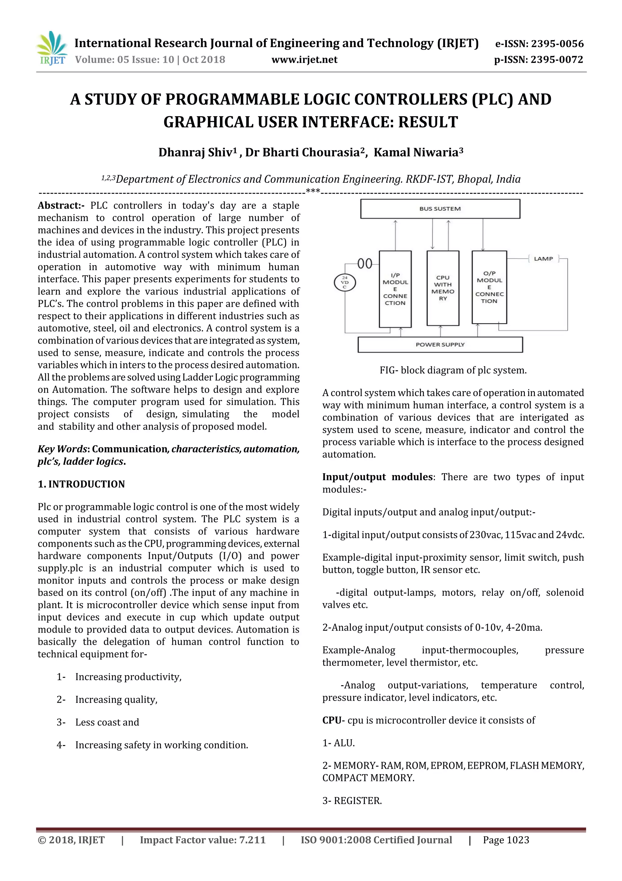
International Research Journal of Engineering and Technology (IRJET) e-ISSN: 2395-0056 Volume: 05 Issue: 10 | Oct 2018 www.irjet.net p-ISSN: 2395-0072 © 2018, IRJET | Impact Factor value: 7.211 | ISO 9001:2008 Certified Journal | Page 1023 A STUDY OF PROGRAMMABLE LOGIC CONTROLLERS (PLC) AND GRAPHICAL USER INTERFACE: RESULT Dhanraj Shiv1 , Dr Bharti Chourasia2, Kamal Niwaria3 1,2,3Department of Electronics and Communication Engineering. RKDF-IST, Bhopal, India ----------------------------------------------------------------------***--------------------------------------------------------------------- Abstract:- PLC controllers in today's day are a staple mechanism to control operation of large number of machines and devices in the industry. This project presents the idea of using programmable logic controller (PLC) in industrial automation. A control system which takes care of operation in automotive way with minimum human interface. This paper presents experiments for students to learn and explore the various industrial applications of PLC’s. The control problems in this paper are defined with respect to their applications in different industries such as automotive, steel, oil and electronics. A control system is a combination of variousdevicesthatareintegratedassystem, used to sense, measure, indicate and controls the process variables which in inters to the process desired automation. All the problemsaresolvedusingLadderLogic programming on Automation. The software helps to design and explore things. The*computer program used for simulation. This project*consists of design,*simulating the model and*stability and other analysis of proposed model. Key Words: Communication,characteristics,automation, plc’s, ladder logics. 1. INTRODUCTION Plc or programmable logic control is one of the most widely used in industrial control system. The PLC system is a computer system that consists of various hardware components such as the CPU,programmingdevices,external hardware components Input/Outputs (I/O) and power supply.plc is an industrial computer which is used to monitor inputs and controls the process or make design based on its control (on/off) .The input of any machine in plant. It is microcontroller device which sense input from input devices and execute in cup which update output module to provided data to output devices. Automation is basically the delegation of human control function to technical equipment for- 1- Increasing productivity, 2- Increasing quality, 3- Less coast and 4- Increasing safety in working condition. FIG- block diagram of plc system. A control system which takes care of operationinautomated way with minimum human interface, a control system is a combination of various devices that are interigated as system used to scene, measure, indicator and control the process variable which is interface to the process designed automation. Input/output modules: There are two types of input modules:- Digital inputs/output and analog input/output:- 1-digital input/output consistsof230vac,115vacand24vdc. Example-digital input-proximity sensor, limit switch, push button, toggle button, IR sensor etc. -digital output-lamps, motors, relay on/off, solenoid valves etc. 2-Analog input/output consists of 0-10v, 4-20ma. Example-Analog input-thermocouples, pressure thermometer, level thermistor, etc. -Analog output-variations, temperature control, pressure indicator, level indicators, etc. CPU- cpu is microcontroller device it consists of 1- ALU. 2- MEMORY-RAM,ROM,EPROM,EEPROM,FLASHMEMORY, COMPACT MEMORY. 3- REGISTER.
International Research Journal of Engineering and Technology (IRJET) e-ISSN: 2395-0056 Volume: 05 Issue: 10 | Oct 2018 www.irjet.net p-ISSN: 2395-0072 © 2018, IRJET | Impact Factor value: 7.211 | ISO 9001:2008 Certified Journal | Page 1024 4- TIMER. 5- COUNTER, and 6- PROCESS IMAGE AREA: - I/P image [area/table], O/P [image area/table]. BUS SYSTEM- bus system transmit data or signal between input, output modules, cup and 3process. TYPE OF PLC- 1- COMPACT and 2- MODULAR. In compact plc memory are flexed I/P module, in Modular I/p module depends on project or customer requirement. Compact plc are less memory and modular plc depending on project there used more memory. In compact any fault is observed in any slot {i/p} so required change hardware {plc’s}, in modular case of fault to any slot {i/p} can be easily handle fault by replacing the slots. LADDER LOGIC PROGRAMING USING SOFTWARE (RS LINX, RS LOGIX 500, SIMATIC MANAGER) One of the widely used methods of controlling PLCs is using Ladder logic programming. The ladder logic diagram is a representation of the steps of programming. INPUT address can be used in series and parallel. OUTPUT address can be used in parallel. OUTPUT address can be used as INPUT address. INPUT address not be used as OUTPUT address. INPUT address can be repeated as INPUT address. OUTPUT latch and unlatch OUTPUT coil. The ladder program is all PLCs follow a template that consists of 2 bus bars that are connected to one another using rung lines. FIG -RS LINX LITE NOTE- RS LINX LITE is for configuration with RSLOGIX500.in RSLOGIX 500 we chosen input/output configuration, microcontroller etc. in this we design programs and run it through RSLOGIX 500. Same in SIMATIC MANAGER SIMATIC MANAGER are using for SIMESNS PLC. FIG- RS LOGIX 500 FIG- SIMATIC MANAGER CONCLUSION A software tool and hardware for teaching/learning the microcontroller based PLC, called EasyLadder, andhasbeen presented. It can be used when describing the PLC architecture, the Ladder logic instruction set or the embedded peripherals operation, and also to write and test Application programs. The main advantages of thisplatform are its versatility, design flexibilityandlowcostcompared to commercially available products as a teaching point of view. It is considered that this platform has an impact in the automation where PLC is the part of system and so student can understand heart of the system. The source codes of EasyLadder are open to studentsothateveryonemakestheir own small PLC using editing the codes. Also, the authors consider that this system is a platform on which a more powerful PLC can be developed in future. The results of the application of our approachtoeducationhavebeenexcellent both in terms of student’s motivation and knowledge.
International Research Journal of Engineering and Technology (IRJET) e-ISSN: 2395-0056 Volume: 05 Issue: 10 | Oct 2018 www.irjet.net p-ISSN: 2395-0072 © 2018, IRJET | Impact Factor value: 7.211 | ISO 9001:2008 Certified Journal | Page 1025 RESULT This project we have learn how to design a program and familiar to plc drives. Students are learn here how to create program. The plc drives are typically chosen for interface with program. Plc Drives are helping to run program and monitoring. This project helps student to create program and run through plc drive. Software is used to create program and helps to understand it. Students can use this project to understand plc programming and drive understanding. This project helps to learners to understand plc programming. ACKNOWLEDGMENT I am grateful to staff member of electronics and communication department of RKD Institute of Science And Technology, Bhopal (M.P.) for the opportunitytopursuethis Master’s project in a specialized area of interest and wish to express my sincere appreciation and gratitude to himforhis guidance throughout the course of this project. My sincere thank also to all other faculty members of the department for their valuable suggestions and comments. REFERENCE [1] Michael Vine, “Visual Basic Programming (For the absolute beginner)”. [2] Vincet Himpe, “Visual Basic for electronics engineering applications”. [3] David I. Schneider, “Computer Programming Concepts and Visual Basic”. [4] Clayton Walnum, “Complete Idiot's Guide to Visual Basic 6” ISBN: 078971812x, Publication Date: 12/15/98. [5] L.A. BRYAN and E.A. BRYAN.” ProgrammableControllers. [6] Theory and implementation, by L.A. BRYAN and E.A. BRYAN. [7] Prolific Institute for Automation. [8] Schuler Industrial Automation modules.

IRJET-A Study of Programmable Logic Controllers (PLC) and Graphical User Interface: Result

  • 1.
    International Research Journalof Engineering and Technology (IRJET) e-ISSN: 2395-0056 Volume: 05 Issue: 10 | Oct 2018 www.irjet.net p-ISSN: 2395-0072 © 2018, IRJET | Impact Factor value: 7.211 | ISO 9001:2008 Certified Journal | Page 1023 A STUDY OF PROGRAMMABLE LOGIC CONTROLLERS (PLC) AND GRAPHICAL USER INTERFACE: RESULT Dhanraj Shiv1 , Dr Bharti Chourasia2, Kamal Niwaria3 1,2,3Department of Electronics and Communication Engineering. RKDF-IST, Bhopal, India ----------------------------------------------------------------------***--------------------------------------------------------------------- Abstract:- PLC controllers in today's day are a staple mechanism to control operation of large number of machines and devices in the industry. This project presents the idea of using programmable logic controller (PLC) in industrial automation. A control system which takes care of operation in automotive way with minimum human interface. This paper presents experiments for students to learn and explore the various industrial applications of PLC’s. The control problems in this paper are defined with respect to their applications in different industries such as automotive, steel, oil and electronics. A control system is a combination of variousdevicesthatareintegratedassystem, used to sense, measure, indicate and controls the process variables which in inters to the process desired automation. All the problemsaresolvedusingLadderLogic programming on Automation. The software helps to design and explore things. The*computer program used for simulation. This project*consists of design,*simulating the model and*stability and other analysis of proposed model. Key Words: Communication,characteristics,automation, plc’s, ladder logics. 1. INTRODUCTION Plc or programmable logic control is one of the most widely used in industrial control system. The PLC system is a computer system that consists of various hardware components such as the CPU,programmingdevices,external hardware components Input/Outputs (I/O) and power supply.plc is an industrial computer which is used to monitor inputs and controls the process or make design based on its control (on/off) .The input of any machine in plant. It is microcontroller device which sense input from input devices and execute in cup which update output module to provided data to output devices. Automation is basically the delegation of human control function to technical equipment for- 1- Increasing productivity, 2- Increasing quality, 3- Less coast and 4- Increasing safety in working condition. FIG- block diagram of plc system. A control system which takes care of operationinautomated way with minimum human interface, a control system is a combination of various devices that are interigated as system used to scene, measure, indicator and control the process variable which is interface to the process designed automation. Input/output modules: There are two types of input modules:- Digital inputs/output and analog input/output:- 1-digital input/output consistsof230vac,115vacand24vdc. Example-digital input-proximity sensor, limit switch, push button, toggle button, IR sensor etc. -digital output-lamps, motors, relay on/off, solenoid valves etc. 2-Analog input/output consists of 0-10v, 4-20ma. Example-Analog input-thermocouples, pressure thermometer, level thermistor, etc. -Analog output-variations, temperature control, pressure indicator, level indicators, etc. CPU- cpu is microcontroller device it consists of 1- ALU. 2- MEMORY-RAM,ROM,EPROM,EEPROM,FLASHMEMORY, COMPACT MEMORY. 3- REGISTER.
  • 2.
    International Research Journalof Engineering and Technology (IRJET) e-ISSN: 2395-0056 Volume: 05 Issue: 10 | Oct 2018 www.irjet.net p-ISSN: 2395-0072 © 2018, IRJET | Impact Factor value: 7.211 | ISO 9001:2008 Certified Journal | Page 1024 4- TIMER. 5- COUNTER, and 6- PROCESS IMAGE AREA: - I/P image [area/table], O/P [image area/table]. BUS SYSTEM- bus system transmit data or signal between input, output modules, cup and 3process. TYPE OF PLC- 1- COMPACT and 2- MODULAR. In compact plc memory are flexed I/P module, in Modular I/p module depends on project or customer requirement. Compact plc are less memory and modular plc depending on project there used more memory. In compact any fault is observed in any slot {i/p} so required change hardware {plc’s}, in modular case of fault to any slot {i/p} can be easily handle fault by replacing the slots. LADDER LOGIC PROGRAMING USING SOFTWARE (RS LINX, RS LOGIX 500, SIMATIC MANAGER) One of the widely used methods of controlling PLCs is using Ladder logic programming. The ladder logic diagram is a representation of the steps of programming. INPUT address can be used in series and parallel. OUTPUT address can be used in parallel. OUTPUT address can be used as INPUT address. INPUT address not be used as OUTPUT address. INPUT address can be repeated as INPUT address. OUTPUT latch and unlatch OUTPUT coil. The ladder program is all PLCs follow a template that consists of 2 bus bars that are connected to one another using rung lines. FIG -RS LINX LITE NOTE- RS LINX LITE is for configuration with RSLOGIX500.in RSLOGIX 500 we chosen input/output configuration, microcontroller etc. in this we design programs and run it through RSLOGIX 500. Same in SIMATIC MANAGER SIMATIC MANAGER are using for SIMESNS PLC. FIG- RS LOGIX 500 FIG- SIMATIC MANAGER CONCLUSION A software tool and hardware for teaching/learning the microcontroller based PLC, called EasyLadder, andhasbeen presented. It can be used when describing the PLC architecture, the Ladder logic instruction set or the embedded peripherals operation, and also to write and test Application programs. The main advantages of thisplatform are its versatility, design flexibilityandlowcostcompared to commercially available products as a teaching point of view. It is considered that this platform has an impact in the automation where PLC is the part of system and so student can understand heart of the system. The source codes of EasyLadder are open to studentsothateveryonemakestheir own small PLC using editing the codes. Also, the authors consider that this system is a platform on which a more powerful PLC can be developed in future. The results of the application of our approachtoeducationhavebeenexcellent both in terms of student’s motivation and knowledge.
  • 3.
    International Research Journalof Engineering and Technology (IRJET) e-ISSN: 2395-0056 Volume: 05 Issue: 10 | Oct 2018 www.irjet.net p-ISSN: 2395-0072 © 2018, IRJET | Impact Factor value: 7.211 | ISO 9001:2008 Certified Journal | Page 1025 RESULT This project we have learn how to design a program and familiar to plc drives. Students are learn here how to create program. The plc drives are typically chosen for interface with program. Plc Drives are helping to run program and monitoring. This project helps student to create program and run through plc drive. Software is used to create program and helps to understand it. Students can use this project to understand plc programming and drive understanding. This project helps to learners to understand plc programming. ACKNOWLEDGMENT I am grateful to staff member of electronics and communication department of RKD Institute of Science And Technology, Bhopal (M.P.) for the opportunitytopursuethis Master’s project in a specialized area of interest and wish to express my sincere appreciation and gratitude to himforhis guidance throughout the course of this project. My sincere thank also to all other faculty members of the department for their valuable suggestions and comments. REFERENCE [1] Michael Vine, “Visual Basic Programming (For the absolute beginner)”. [2] Vincet Himpe, “Visual Basic for electronics engineering applications”. [3] David I. Schneider, “Computer Programming Concepts and Visual Basic”. [4] Clayton Walnum, “Complete Idiot's Guide to Visual Basic 6” ISBN: 078971812x, Publication Date: 12/15/98. [5] L.A. BRYAN and E.A. BRYAN.” ProgrammableControllers. [6] Theory and implementation, by L.A. BRYAN and E.A. BRYAN. [7] Prolific Institute for Automation. [8] Schuler Industrial Automation modules.